International Journal of Advanced Engineering, Management and Science (IJAEMS) [Vol-2, Issue-5, May- 2016] Infogain Publication (Infogainpublication.com) ISSN : 2454-1311
www.ijaems.com Page | 263
A Comparative Study on Effects of Regular and
Irregular Structures Subjected to Lateral
Loading by Equivalent Static Method and
Response Spectrum Method
Prabesh Sharma
1, D. R Rajendra .S
2, Vanisree C.N
31
P.G Student, Department of Civil Engineering, N.C.E.T, Visvesvaraya Technological University, Bangalore, India
2Professor and Head (P.G) Student, Department of Civil Engineering, N.C.E.T, Visvesvaraya Technological University,
Bangalore, India
3Assistant Professor, Department of Civil Engineering, N.C.E.T, Visvesvaraya Technological University, Bangalore, India
Abstract— This paper aims in thoroughly examine and
have a comparative study of the behavior of regular and irregular R.C building with and without shear wall for seismic and wind load activities in different zones of India through equivalent static method and response spectrum method. For this purpose, regular and irregular R.C structures are taken and analyzed against earthquake and wind forces in different zones of India. Further shear wall is introduced in both regular and irregular structure and again analyzed in different zones. For structural irregularity, vertical irregularity and plan irregularity are taken into account. These irregularities are taken as per Indian standard code, IS 1893 (Part I): 2002. The whole models were analysed with the help of CYPE Software. In current study drifts has been considered in both X and Y directions and are compared with structure shear wall.
Keywords— Irregular Structures, Seismic Load, Wind Load, Shear Wall, CYPE.
I. INTRODUCTION
For the last decade there is a gradual increase of irregular structures due to enhancement in architecture. Irregular structures leads to remarkable eccentricity between center of mass and stiffness. This leads to lateral response due to which damage occurs. During earthquake, surface of the ground will be subjected to six different motion i.e three translations and three rotations. Each of these components are uncorrelated. Due to uncorrelated components the damage of a structure are unconfined. During Nepal Earthquake (2015), the failure due to vertical and horizontal irregularity was encountered. The main problem is the lack of study of irregular structure. Provision of shear wall can stabilize stiffness, mass and increase the strength of a structure. The scope of this
study is to compare the shear wall performance for regular and irregular structures in different zones of India by equivalent static method and response spectrum method.
II. METHODOLOGY
Analysis of a structure is done by equivalent static method and response spectrum method. The main difference between this methods lies in the magnitude and distribution of lateral forces over the height of a structure. The analysis of structure is done by using CYPE software. The different configuration position of shear wall in Reinforced Concrete building were analyzed for under seismic and wind analysis. The data used is as per earthquake loading (IS: 1983-2002) and Wind loading (IS: 875 Part 3).
III. SHEARWALLLOCATION
Location of Shear Wall is an important part which effects the response of a structure. Shear wall is a good mechanism for lateral loads resisting, but the placement of shear walls should be made judiciously. In case of regular structure, shear walls at mid-sides perform better in major number of cases (Anshul Sud et at.,2014). Incorporation of shear walls improves the seismic performance of the building with re-entrant corner i.e plan irregularity buildings and strengthening the inner notch was found to be much efficient compared to strengthening outer notch (Divyashree M et at. (2014)). In case of vertical irregularity, placement of shear wall mainly depends on the location of centre of mass and centre of rigidity.
IV. MODELLINGANDANALYSIS
considered. Loads are considered with reference to relevant codes of IS 875 part1- 1987, IS 875 part3-1987, IS 1893 part1-2002. The dead and imposed loads of all the reinforced concrete members will be given as self-weights of the members; all the floor loads expressed as load per square area is applied as distributed floor loads onto the supporting beams. Wall loads are taken as line load onto the supporting beams; the wind and earthquake loads are applied as lateral loads at each floor level. Material grades of M25 & Fe 415 is used. Six-storey RC office structure is located in seismic zone-II, zone-III, and zone-IV and V on medium soil. Thickness of slab is 150mm. Ordinary moment-resisting frame (OMRF) is taken for analysis. These frames are subjected to dead load of 1.5 kN/m2, live load of 2 kN/m2 on all floors, wall load of 12 kN/m2, parapet load of 5kN/m2 on roof (as per IS 875-part-2) earthquake loads as per IS 1893:2002 and wind load as per IS 875 Part 3. More than 45 load combinations are taken for analysis. Importance Factor ‘I’ equal to 1, Response reduction factor ‘R’ as 3 and Damping Ratio as 5 is considered for all structures. In case of wind analysis Terrain Category is taken as I (Exposed open terrain with few or no obstructions and in which the average height of any object surrounding the structure is less than 1.5 m) and Land Orography is taken as flat.Six structures have been considered with one regular and two irregular with and without shear wall. For regular structural in x-direction there are 5 bays, each of 5 m width and in z-direction also there are 5 bays, each of 5 m width. For Plan irregular structure it has 64% re-entrant corner in L shape and in case of vertical irregular structure irregularity taken is 80 % as per IS 1893:2002.
Table 1: Structural properties of structures
Zone 2:
Zone Area- Bangalore Beam Dimension- 230X450mm Column Dimension- 230X900mm Basic Wind Speed- 33 m/s
Zone 3:
Zone Area- Ahmedabad Beam Dimension- 230X650mm Column Dimension- 300X900mm Basic Wind Speed- 39 m/s
Zone 4:
Zone Area- Darjeeling Beam Dimension- 230X650mm Column Dimension- 300X900mm Basic Wind Speed- 47 m/s
Zone 5:
Zone Area- Bhuj Beam Dimension- 450X900mm Column Dimension- 450X900mm Basic Wind Speed- 50 m/s
Frame elements consist of columns and beams of different dimensions for different zones because in different zone load acting on a structure are different. The storey drifts at various floors are determined from response spectrum method and equivalent static method. For different structure different configurations of shear wall have been considered to evaluate the effect of shear wall when subjected to lateral loadings. Configuration of shear walls for different structures is shown table 2.
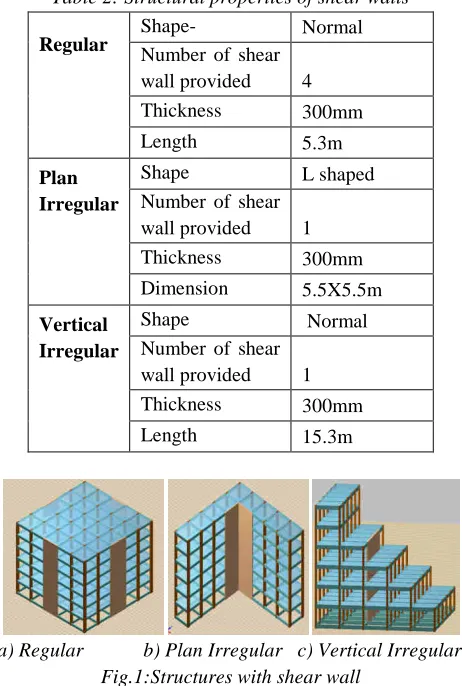
Table 2: Structural properties of shear walls
Regular
Shape- Normal Number of shear
wall provided 4 Thickness 300mm Length 5.3m
Plan Irregular
Shape L shaped Number of shear
wall provided 1 Thickness 300mm Dimension 5.5X5.5m
Vertical Irregular
Shape Normal Number of shear
wall provided 1 Thickness 300mm Length 15.3m
a) Regular b) Plan Irregular c) Vertical Irregular Fig.1:Structures with shear wall
V. RESULTANDDISCUSSION
Drifts are considered to identify the structural response of regular and irregular structures with and without shear wall by equivalent static method and response spectrum method. Also wind load has been considered to identify the response of a structures. Result obtain from the analysis are graphically represented for the following structures:
International Journal of Advanced Engineering, Management and Science (IJAEMS) Infogain Publication (Infogainpublication.com
www.ijaems.com
ESM WS-X=Drift from equivalent static method for a structure without shear wall in x direction
ESM SW-X= Drift from equivalent static method for a structure with shear wall in x direction
RSM WS-X= Drift from response spectrum method for a structure without shear wall in x direction
ESM SW-X= Drift from response spectrum method for a structure with shear wall in x direction
ESM WS-Y=Drift from equivalent static method for a structure without shear wall in y direction
ESM SW-Y= Drift from equivalent static method for a structure with shear wall in y direction
RSM WS-Y= Drift from response spectrum method for a structure without shear wall in y direction
ESM SW-Y= Drift from response spectrum method for a structure with shear wall in y direction
Fig.2: Comparision of drifts for regular structure(X direction) in zone II.
Fig.3: Comparision of drifts for regular structure(Y direction) in zone II.
Fig.4: Comparision of drifts for Plan irregular structure(X-direction) in zone II.
International Journal of Advanced Engineering, Management and Science (IJAEMS) Infogainpublication.com)
X=Drift from equivalent static method for a
X= Drift from equivalent static method for a
X= Drift from response spectrum method for a
X= Drift from response spectrum method for a
Y=Drift from equivalent static method for a
Y= Drift from equivalent static method for a
se spectrum method for a
Y= Drift from response spectrum method for a
2: Comparision of drifts for regular
structure(X-Comparision of drifts for regular
structure(Y-Comparision of drifts for Plan irregular direction) in zone II.
Fig.5: Comparision of drifts for Plan irregular structure(Y-direction) in zone II.
Fig.6: Comparision of drifts for Vertical irregular structure(X-direction) in zone II.
Fig.7: Comparision of drifts for Vertical irregular structure(Y-direction) in zone II.
Fig.8: Comparision of drifts for regular structure(X direction) in zone
Fig.9: Comparision of drifts for regular structure(Y direction) in zone I
[Vol-2, Issue-5, May- 2016] ISSN : 2454-1311
Page | 265
Comparision of drifts for Plan irregular direction) in zone II.
ion of drifts for Vertical irregular direction) in zone II.
7: Comparision of drifts for Vertical irregular direction) in zone II.
8: Comparision of drifts for regular structure(X-direction) in zone III.
Fig.10: Comparision of drifts for Plan irregular structure(X-direction) in zone III.
Fig.11: Comparision of drifts for Plan irregular structure(Y-direction) in zone III.
Fig.12: Comparision of drifts for Vertical irregular structure(X-direction) in zone III.
Fig.13: Comparision of drifts for Vertical irregular structure(Y-direction) in zone III.
Fig.14: Comparision of drifts for regular structure(X direction) in zone IV.
10: Comparision of drifts for Plan irregular direction) in zone III.
11: Comparision of drifts for Plan irregular direction) in zone III.
Comparision of drifts for Vertical irregular direction) in zone III.
Comparision of drifts for Vertical irregular direction) in zone III.
Comparision of drifts for regular
structure(X-Fig.15: Comparision of drifts for regular structure(Y direction) in zone IV.
Fig.16: Comparision of drifts for Plan irregular structure(X-direction) in zone IV.
Fig.17: Comparision of drifts for Plan irregular structure(Y-direction) in zone IV.
Fig.18: Comparision of drifts for Vertical irregular structure(X-direction) in zone IV.
Fig.19: Comparision of drifts for Vertical irregular structure(Y-direction) in zone IV.
Comparision of drifts for regular structure(Y-direction) in zone IV.
Comparision of drifts for Plan irregular direction) in zone IV.
Comparision of drifts for Plan irregular direction) in zone IV.
Comparision of drifts for Vertical irregular direction) in zone IV.
International Journal of Advanced Engineering, Management and Science (IJAEMS) Infogain Publication (Infogainpublication.com
www.ijaems.com
Fig.20: Comparision of drifts for regular s direction) in zone V.
Fig.21: Comparision of drifts for regular s direction) in zone V.
Fig.22: Comparision of drifts for Plan irregular structure(X-direction) in zone V.
Fig.23: Comparision of drifts for Plan irregular structure(Y-direction) in zone V.
Fig.24: Comparision of drifts for Vertical irregular structure(X-direction) in zone V.
International Journal of Advanced Engineering, Management and Science (IJAEMS) Infogainpublication.com)
Comparision of drifts for regular
structure(X-Comparision of drifts for regular
structure(Y-Comparision of drifts for Plan irregular direction) in zone V.
Comparision of drifts for Plan irregular direction) in zone V.
Comparision of drifts for Vertical irregular direction) in zone V.
Fig.25: Comparision of drifts for Vertical irregular structure(Y-direction) in zone V.
VI. CONCLUSION
To obtain accurate results, comparison has been done with respect to its particular zones. The study of regular and irregular structure with and without shear wall in different zones of India by equivalent static method and response spectrum method leads to the following conclusions:
1. Regular structure shows better performance a compared to irregular structure
and wind loading and response spectrum methods gives higher value for drifts as compared to equivalent static method.
2. In-case of regular structure shear wall will reduce drift by 70-80% in X
Y-direction if analysis is done by response spectrum method and if analysis is done by equivalent static method drift is reduced by 50 60% in X-direction and by 40
3. In-case of plan irregular structure shear wall will reduce drift by 60-80% in X
50% in Y-direction if analysis is done by response spectrum method and if analysis is done by equivalent static method drift is reduced by 40 50% in X-direction and by 10
4. In-case of plan irregu reduce drift by 15-25
80% in Y-direction if analysis is done by response spectrum method and if analysis is done by equivalent static method drift is reduced by 15% in X-direction and by
ACKNOWLEDGEMENTS
First and foremost we would like to thank
for guiding us in the right direction and helping us with his valuable suggestions. We are also grateful to the authors of various papers and journals cited in our research paper. Lastly we would like to thank our friends, family and the Department of Civ
[Vol-2, Issue-5, May- 2016] ISSN : 2454-1311
Page | 267
Comparision of drifts for Vertical irregular direction) in zone V.
CONCLUSION
, comparison has been done particular zones. The study of regular with and without shear wall in different zones of India by equivalent static method and response spectrum method leads to the following
Regular structure shows better performance as compared to irregular structure under earthquake and wind loading and response spectrum methods gives higher value for drifts as compared to equivalent static method.
case of regular structure shear wall will reduce 80% in X-direction and by 55-65% in direction if analysis is done by response spectrum method and if analysis is done by equivalent static method drift is reduced by
50-direction and by 40-50 % in Y-50-direction. case of plan irregular structure shear wall will 80% in X-direction and by 20-direction if analysis is done by response spectrum method and if analysis is done by equivalent static method drift is reduced by
40-direction and by 10-15 % in Y-40-direction. case of plan irregular structure shear wall will 25% in X-direction and by
60-if analysis is done by response spectrum method and if analysis is done by equivalent static method drift is reduced by
10-direction and by 40-50 % in Y-10-direction.
ACKNOWLEDGEMENTS
REFERENCES
[1] Amin Alavi and P.Srinivasa Rao, on “Effect of Plan Irregular R.C Building in High Seismic Zones”. American Journal of Basic and Applied Science(AJBAS), 7(13):1-6, 2013
[2] M.C.G Pastor and C.F Fernandez, Department of research and development CYPE Ingenious, Alicante, Spain on “Structural Analysis with Different International Standards of Buildings Subjected to Seismic Loads”. Int. Journal for Housing Science, Vol.35, No.3 pp. 149-158, 2011. [3] M. Ashraf, Z.A. Siddiqi and M.A. Javed Department
of Civil Engineering, University of Engineering and Technology, Lahore, Pakistan, on “Configuration of a Multi-storey Building Subjected to Lateral Forces”. Asian Journal of Civil Engineering (Building and Housing) vol. 9, no. 5 (2008) pages 525-537.
[4] Divyashree M, Bhavyashree B.N, Gopi Siddappa, Dept. of Civil Engineering, PES College of Engineering, Mandya, Karnataka, India on Comparison of Bracings and Shear Walls as Seismic Strengthening Methods to Buildings with Plan Irregularities in International Journal of Research in Engineering and Technology ISSN: 2319-1163 to ISSN: 2321-7308.
[5] IS 1893-2002: Criteria for Earthquake Resistant Design of Structures.
[6] IS 456-2002: Plain and Reinforced Concrete
[7] S.K. Duggal on “Earthquake Resistance Design of Structures”