Implementation of DS Finite Impulse Response
Filter Using Multiple Constant Multiplications
Prof Abhijit G Kalbande
Assistant Professor EXTC DepartmentP.R.M.C.E.A.M.Badnera Amravati, M.S, India [email protected]
Abstract—In the last two decades, many efficient algorithms and architectures have been introduced for the design of low complexity bit-parallel multiple constant multiplications (MCM) operation which dominates the complexity of many digital signal processing systems. On the other hand, little attention has been given to the digit-serial MCM design that offers alternative low complexity MCM operations albeit at the cost of an increased delay. In this paper, we address the problem of optimizing the gate-level area in digit-serial MCM designs and introduce high-level synthesis algorithms, design architectures, and a computer aided design tool. Experimental results show the efficiency of the proposed optimization algorithms and of the digit-serial MCM architectures in the design of digit-serial MCM operations and finite impulse response filters. Finite impulse response (FIR) filters are widely used in digital signal processing applications due to their stability and linear phase characteristics. FIR filters have a large number of multiplications involved in the filter algorithm, which are usually implemented using fixed-point or integer number representations with the filter coefficients being represented by a finite number of bits. In hard-wired ASIC designs, multiplication operations are replaced by shift-and-add operations towards multiplier less FIR filter design. From a power perspective, the fewer the number of adders, the less power the filter will consume. The most common approaches to the implementation of digital filtering algorithms are general purpose digital signal processing chips for audio applications, or special purpose digital filtering chips and application-specific integrated circuits (ASICs) for higher rates. This project describes an approach to the implementation of digital filter algorithms on field programmable gate arrays (FPGAs).
Keywords— Reduce dynamic power dissipation, increase computational ability, simple H/W, require less area/size, and also increase the operational speed.
I. INTRODUCTION
Typically the digital filter can be classified into two classes known as FIR Filter and IIR Filter , here FIR Filter are paltry plot with the help of CAD tool and this IIR Filter are difficult to design and they suffer from stability problem . FIR filter needed small data word length than IIR filter; however they required higher order than IIR filter of equal magnitude specification and they sometimes explain small delay that makes them unsuitable for many application. The transfer function of FIR filter of order M is,
H(Z) = ∑ h(n)𝑍−𝑛 𝑀
𝑛=0
H(Z) =ℎ(0)𝑍
𝑚+ ℎ(1)𝑍𝑚−1+ ℎ(0)𝑍𝑚+ ℎ(𝑚 − 1)Z + ℎ(𝑚)
𝑍𝑚
Fig.1 FIR filters implementations in Direct form, Transposed form with generic multiplier & Transposed form with an MCM block.[2]
Although area-, delay-, and power-efficient multiplier architectures, such as Wallace [2] and modified Booth [3] multipliers, have been present, the full flexibility of a multiplier is not essential for the constant multiplications, due to which filter coefficients are fixed and determined beforehand by the DSP algorithms [4]. Due to which the multiplication of filter coefficients with the input data is normally applied under a shift-adds architecture [5], where each constant multiplication is realized using addition/subtraction and shift operations in an MCM operation [Fig. 1(c)].[2]
In the last few years, number efficient algorithms and architectures have been presented for the design of low complexity bit-parallel multiple constant multiplications (MCM) operation which shows the complexity of many digital signal processing systems. On the opposite side, little attention has been given to the digit-serial MCM design that gives alternative low complexity MCM operations albeit at the cost of rising delay. In this paper, we present the problem of optimizing the gate-level area in digit-serial MCM designs and show high level synthesis algorithms, design architectures, and a computer aided design tool. Experimental results show the efficiency of the presented optimization algorithms and of the digit-serial MCM architectures in the design of digit-serial MCM operations as well as finite impulse response filters.[2]
II. DIGITAL SERIAL FIR FILTER SYSTEM
For the shift-adds implementation of constant multiplications, a simple method, normally known as digital based recoding [6], at the first it defines the constants in binary. Then, for each “1” in the binary representation of the constant, as per to its bit position, it shifts the variable and adds up the shifted variables to get the result. As a simple example, assume the constant multiplications 29x and 43x. Their decompositions in binary are listed as follows:
29x = (11101) binx = x << 4 + x << 3 + x << 2 + x 43x = (101011) binx = x<< 5 + x << 3 + x << 1 + x.
Which requires six addition operations as illustrated in Fig. 2(a).[2]
Fig.2 Shift-adds implementations of 29x and 43x. (a) Without partial product sharing [6] and with partial product sharing. (b) Exact CSE algorithm [9]. (c) Exact GB algorithm [12].
The digit-based recoding technique does not contain the sharing of common partial products, which minimizes numbers of operations and, consequently, also reduction in area as well as reduction in power dissipation of the MCM design at the gate level. Due to which, the fundamental optimization problem, know as the MCM problem, is defined as finding the minimum number of addition and subtraction operations which design the constant multiplications. one thing is important is that” in bit-parallel design of constant multiplications, shifts can be realized using only wires in hardware without representing any area cost”. Subexpression elimination (CSE) algorithms [7]–[9] and graph-based (GB) techniques [10]–[12]. At the first the CSE algorithms essence all Subexpression from the representations of the constants when they are defined under binary, canonical signed digit (CSD) [7], or minimal signed digit (MSD) [8]. Then, they discover theSSSSS “best” Subexpression, normally the most common, to be shared among the constant multiplications. The GB methods are not limited to any particular number representation and assume a larger number of alternative implementations of a constant, yielding better solutions than the CSE algorithms, as shown the algorithms designed for the MCM problem can be classified in two types common in [11] and [12].
Returning to our example in Fig. 2, the exact CSE algorithm of [9] gives a solution with four operations by serching the most common partial products 3x = (11)binx and 5x = (101)binx when constants are defined under binary, as illustrated in Fig. 2(b). On the other hand, the exact GB algorithm [12] finds a solution with the least number of operations by sharing the common partial product 7x in both multiplications, as shown in Fig. 2(c). Note that the partial product 7x = (111) binx cannot be extracted from the binary representation of 43x in the exact CSE algorithm [9]
II. LITERATURE REVIEW
A. Levent Aksoy, Cristiano Lazzari, Eduardo Costa, Paulo Flores, and José Monteiro. ( MARCH 2013). [1]
In this paper author address the problem of optimizing the gate-level area in digit-serial MCM designs and introduce high gate-level synthesis algorithms, design architectures, and a computer aided design tool. Experimental results show the efficiency of the proposed optimization algorithms and of the digit-serial MCM architectures in the design of digit-serial MCM operations and finite impulse response filters.
B. C. S. WALLACEt (February 1963)[2]
In this paper author suggested that the economics of present large- scale scientific computers could benefit from a greater investment in hardware to mechanize multiplication and division than is now common. As a move in this direction, a design is developed for a multiplier which generates the product of two numbers using purely combinational logic, i.e., in one gating step.
C. W. Lynn Gallagher and Earl E. Swartzlander. (June 1995). [3]
In this paper author introduce the Reduced Area multiplier, the Wallace multiplier, and the Dadda multiplier each offer fast multiplication of signed binary numbers with the use of a large adder tree and a carry lookahead adder. However, their complexity makes them undesirable for some applications.
D. James H. Mcclellan, Thomas W. Parks, and Lawrence R. Rabiner. (December 1973) [4]
This paper author presents a general-purpose computer program which is capable of designing a large class of optimum FIR linear phase digital filters. The program has options for designing such standard filters also low-pass, high-pass, band-pass, and bandstop filters, as well as multipass band & stop band filters, differentiators, and Hilbert transformers.
E. Huy T. Nguyen and Abhijit Chatterjee. (August 2000). [5] Most DSP synthesis tools perform limited architectural transformations to optimize hardware and power. Multiplications are often implemented with shift-and-add operations for hardware efficiency. In this paper author propose an optimization that combines a numerical transformation called number-splitting with a shift-and-add decomposition scheme.
III.PROPOSED APPROACH
Here we propose efficient filter, the name of that filter given as digit serial adder multiple constant multiplication filter. As we know that adder, multiplier and D flip-flop are main part of digital filter. Here for developing the efficient digital filter we have to improve that basic component, so here in this project we modified adder as well as multiplier. In that in place of simple adder we will used digit serial adder and also in place of normal multiplier we can used shift add techniques.
In this complete paper, we design three digital filters, namely 1. Digital filter (direct form).
2. Digital filter (transpose form). 3. Digit serial MCM filter.
1. Design of digital filter (Direct Form):-
The overall design processes of digital filter are given in following flow chart. The complete design flow of18 tap digital filter is given in above flow chart the main structure of it is as given below. The basic structure of digital filter in direct form is as given below it contain four basic block i;e h_coeff2, Er_zero1,df_331and df_filter1.it has 8 bit input i;e X(7:0) and 33 bit output R(32:0).
Fig.3: - FIR Filter implementation (direct form) in AHDL
We will go through them one by one, In this filter contain following basic
Coefficient blocks (h_coeff )
By using this block we can provide different coefficient to digital filter. These filter coefficients are convoluted with applied original data and then at the output of filter we get convoluted output. Here in following figure we apply filter coefficient totally we apply 18 coefficients (h0 toh17).
Er_zero1 block
This block is normally used in every filter, this block is used for making the overall input and output equal to zero .when we have to make the output and input equal to zero then it becomes directly zero. It has 33 bit output r(32:0).
dff_331 block
In this project we have to design filter which work on digit not on the bit, so here the output will get in bit format but we required output in digit format. This block is simply used as a D flip-flop for converting bit input to digit output. This block has three inputs and one output that three input are d(32:0) , clock , and reset and single output of 33 bit that is q(32:0).
df_filter1
data,and the output of multiplier is of 15 bit.here in this design totally 18 adder and 18 multipler are to used,and 17 Dflip-flop are to used which is connted with multiplier .
2. Design of digital filter (Transpose Form)
The overall design processes of digital filter in transpose is given in following flow chart. The complete design flow of18 tap digital filter is given in above flow chart. The main structure of it is as given below. The basic structure of digital filter in transpose form is as given below it contain four basic block i;e h_coeff2, Er_zero1,df_331and tf_filter1.it has 8 bit input i;e X(7:0) and 33 bit output R(32:0).
Fig.4. - FIR Filter implementation (Transpose form) in AHDL
Coefficient blocks (h_coeff2)
By using this block we can provide different coefficient to digital filter. These filter coefficients are convoluted with applied original data and then at the output of filter we get convoluted output. Here in following figure we apply filter coefficient totally we apply 18 coefficients (h0 toh17).
Er_zero1 block
This block is normally used in every filter, this block is used for making the overall input and output equal to zero .when we have to make the output and input equal to zero then it becomes directly zero. It has 33 bit output r(32:0).
dff_331 block
In this project we have to design filter which work on digit not on the bit, so here the output will get in bit format but we required output in digit format. This block is simply used as a D flip-flop for converting bit input to digit output. This block has three inputs and one output that three input are d(32:0) , clock , and reset and single output of 33 bit that is q(32:0).
tf_filter1
This is the main important block of overall structure of digital filter in direct form.The internal block diagram of
this block is as given in figure. it contain three block that is adder ,multiplier and D filp-flop.here the adder having the two input ,first is 33 bit input i;eEr(32:0) and other is from multiplier block which is 15 bit input i:e also the output of adder is is 33 bit. here in this design simple adder is used. another block is multiplier ,here in this design simple multiplier given which has two input which are 8 bit coefficent and 8 bit is of applied input data,and the output of multiplier is of 15 bit.here in this design totally 18 adder and 18 multipler are to used,and 17 Dflip-flop are to used which is connted with multiplier .
3. Digit serial MCM FIR filter
The overall design processes of digit serial MCM FIR filter are given in following flow chart. as we know that the adder, multiplier and D flip-flop are basic part of digital filter, here in this design we try to improve adder as well as multiplier of filter and D flip-flop remain as it is .in that adder is not simple adder in place of that we design digit serial adder and in place of simple multiplier we design MCM that is multiple constant multiplication, hence the name gives to design as DSA_MCM filter.
Fig.5 -Digit Serial FIR Filter implementation in AHDL
The main structure of this filter design is given below, it contain data generator block , Er_zero2 , Dff_3421 and DSA_MCM_filter1.
Data generator block
By using that block we generate certain data which is to be used for convolution with filter coefficient .Generated data is as given in following figure.
Er_zero2
This block is normally used in every filter, this block is used for making the overall input and output equal to zero .when we have to make the output and input equal to zero then it becomes directly zero. It has 33 bit output r(32:0).
Dff_3421
format but we required output in digit format. This block is simply used as a D flip-flop for converting bit input to digit output. This block has three inputs and one output that three input are d(32:0) , clock , and reset and single output of 33 bit that is q(32:0).
DSA_MCM_filter1
It is a main structure of filter it contain port_adj1, mul_hn, CUSAD2, Digit_adder1.it contain 18 adder and 7 multiplier also in that tapping techniques will be used.
Port_adj1 the main purpose of this block is to inter connection of signal due to which overall size of structure will get minimize .in that tapping techniques are to be used for multiplier.
CUSAD_2
This block contain FSM that is finite state machine, this finite state machine diagram is as given below this will be used for handling seven signal of digit adder automatically.
Mul_hn
Here there are multiple constant coefficient that are used and here multiplication is to be performing by using shift add techniques method such as ,For Ex:- 5= <<2 + 1.
Digit_adder1
Here adder is modified by serial digit adder its internal block diagram is as given below it contain MUX1521, MUX33321, STOP3421 and Digit _SA2The stop3421 will be used for converting the output serial to parallel, at the output of filter we want output in term of digit for that purpose it will convert serial to parallel.
IV. RESULT
The proposed filter has been design and simulated on AHDL and Quartas- II software. We design whole project into some modules and we got the output of all modules successfully. So here we had shown result of both software. Result after compilation on Quartas-II: - The result after compilation is as given in the following table:-
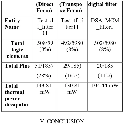
TABLE I. RESULT AFTER COMPILATION ON QUARTAS-II
Specificat ion
Filter Filter Improved
(Direct Form)
(Transpo se Form)
digital filter
Entity Name
Test_d f_filter 11
Test_tf_fi lter11
DSA_MCM _filter1
Total logic elements
508/59 (8%)
492/5980 (8%)
502/5980 (8%)
Total Pins 51/185)
(28%)
29/185)
(16%)
20/185
(11%)
Total thermal power dissipatio
133.81 mW
130.81 mW
104.44 mW
V. CONCLUSION
In this paper, we introduced the 0–1 ILP formalization for designing digit-serial MCM operation with optimal area at the gate level by considering the implementation costs of digit-serial addition, subtraction, and shift operations. Since there are still instances with which the exact CSE algorithm cannot cope, we also proposed an approximate GB algorithm that finds the best partial products in each iteration which yield the optimal gate-level area in digit-serial MCM design. This paper also introduced the design architectures for the digit-serial MCM operation and a CAD tool for the realization of digit-serial MCM operations and FIR filters. The experimental results indicate that the complexity of digit-serial MCM designs can be further reduced using the high-level optimization algorithms proposed in this paper. It was shown that the realization of digit-serial FIR filters under the shift-adds architecture yields significant area reduction when compared to the filter designs whose multiplier blocks are implemented using digit-serial constant multipliers. It is observed that a designer can find the circuit that fits best in an application by changing the digit size.
Acknowledgment
References
[1] L. Wanhammar, DSP Integrated Circuits. New York: Academic, 1999.
[2] Levent Aksoy, Cristiano Lazzari,Eduardo Costa, Paulo Flores, and José Monteiro, “Design of Digit-Serial FIR Filters: Algorithms, Architectures, and a CAD Tool”, IEEE Transc on VLSI SYSTEMS, VOL. 21, NO. 3, MARCH 2013
[3] C. Wallace, “A suggestion for a fast multiplier,” IEEE Trans. Electron. Comput., vol. 13, no. 1, pp. 14–17, Feb. 1964.
[4] W. Gallagher and E. Swartzlander, “High radix booth multipliers using reduced area adder trees,” in Proc. Asilomar Conf. Signals, Syst. Comput., vol. 1. Pacific Grove, CA, Oct.–Nov. 1994, pp. 545–549.
[5] J. McClellan, T. Parks, and L. Rabiner, “A computer program for designing optimum FIR linear phase digital filters,” IEEE Trans. Audio Electroacoust., vol. 21, no. 6, pp. 506–526, Dec. 1973.
[6] H. Nguyen and A. Chatterjee, “Number-splitting with shift-and-add decomposition for power and hardware optimization in linear DSP Synthesis,” IEEE Trans. Very Large Scale Integr. (VLSI) Syst., vol. 8, no. 4, pp. 419–424, Aug. 2000.
[7] M. Ercegovac and T. Lang, Digital Arithmetic. San Mateo, CA: Morgan Kaufmann, 2003.
[8] R. Hartley, “Subexpression sharing in filters using canonic signed digit multipliers,” IEEE Trans. Circuits Syst. II, Exp. Briefs, vol. 43, no. 10, pp. 677–688, Oct. 1996.
[9] I.-C. Park and H.-J. Kang, “Digital filter synthesis based on minimal signed digit representation,” in Proc. DAC, 2001, pp. 468–473.
[10] L. Aksoy, E. Costa, P. Flores, and J. Monteiro, “Exact and approximate
algorithms for the optimization of area and delay in multiple constant multiplications,” IEEE Trans. Comput.-Aided Design Integr. Circuits Syst., vol. 27, no. 6, pp. 1013–1026, Jun. 2008.
[11] A. Dempster and M. Macleod, “Use of minimum-adder multiplier blocks
in FIR digital filters,” IEEE Trans. Circuits Syst. II, Exp. Briefs, vol. 42, no. 9, pp. 569–577, Sep. 1995.
[12] L. Aksoy, E. Costa, P. Flores, and J. Monteiro, “Optimization of area in
digital FIR filters using gate-level metrics,” in Proc. DAC, 2007, pp. 420–423.
[13] L. Aksoy, C. Lazzari, E. Costa, P. Flores, and J. Monteiro, “Optimization
of area in digit-serial multiple constant multiplications at gate-level,” in Proc. ISCAS, 2011, pp. 2737–2740.
[14] R. Hartley and P. Corbett, “Digit-serial processing techniques,” IEEE Trans. Circuits Syst., vol. 37, no. 6, pp. 707–719, Jun. 1990..
[15] P. Cappello and K. Steiglitz, “Some complexity issues in digital signal