Literature Review on Analysis and Optimization of
Digger Machine Blade
Ritesh G. Dhongade
1M.T.Shete
2M. Tech.(Production Engineering) Scholar Asst. Professor
Department of Mechanical Engineering, Department of Mechanical Engineering, Government College of Engineering, Government College of Engineering,
Amravati,444604 India Amravati,444604 India
E-mail: [email protected] E-mail: [email protected]
ABSTRACT: In this paper a detail study is done on
analysis and design optimization of various other agricultural tools and machineries even excavators which are used for removing soil and other purpose. This paper is aimed to show recent development in the field of design and optimization done by various other researchers using number of simulation software presently available. The main advantages of using simulation software is that it will reduce time and rectify errors to make possible changes before production. In this project a Agriculture tool DIGGER MACHINE blade is taken into consideration ,as its going to have direct contact with the soil and maximum wear and tear going to happen to blade. This will help us to estimate the future problem arises in front of blade while working condition.
Keywords: Agriculture tool, Digger m/c, FEM, HYPERWORKS
I. INTRODUCTION
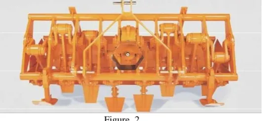
The Work of the “Mechanical digging machine” is same as “old hand digging”: penetration, tear, throwing. The digging machine does not cause the formation of a smooth, compacted and impermeable layer as with ploughing. It leaves the ground broken, friable and permeable. Fertility of soil improved with digger machine because organic or chemical fertilizer is more fully mixed in the soil; because it assures better oxygenation of all the worked soil; because it improve the population of micro-organisms and transformation of organic substances. The physical-chemical structure of soil improve with digging machine so that the yield increase. Using digging machine, working times are reduced, less wear and tear on the tractor. The digging machine requires no efforts of traction so eliminating slip of the tractor wheels. Less horsepower is required (80 H.P tractor) can operates up to 3 meter width shown in fig.2. Digging machine are ideal for vegetables fields, nursery fields, green house, olive groves, vineyards, large fields, when it is not possible to work the soil by equipments. Various forces are acting on the blade as it is in continuous contact with soil hence the resistive force act on the blade. This force are classified into three
1. Cutting force 2. Penetration force 3. Filling force .
Figure 1.
Where, W is the weight of the moving soil wedge, Lt is the length of the tool and Lf is the length of the failure surface, Ø is the angle of soil-soil friction, and δ is the friction between the metal and the blade, R is the force resisting movement of the wedge and F is the total resistive force got from Reece's FEE equation.
Due to this resistive forces stress are generated on blade which will directly reduces the life cycle of the machine. FEM is one of the method to locate the critical point on the machine. Safety factor is used to provide a design margin over the theoretical design.
Simulation of component behaviour is often done using the Finite Element Method. Here, the analyst requires the forces on the component as data for the model. One benefit is that the forces calculated from an Multi Body Dynamic analysis can be used to provide data for a Finite Element analysis. However, there are other reasons that make this a natural way to address several complex design issues.
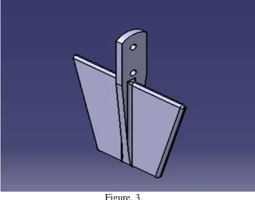
Figure. 3.
II. IMPORTANT CONSIDERATION BEFORE
STARTING ANALYSIS AND OPTIMIZATION
To start analysis and optimization of any machine part, some consideration for designing that part are stated below. 2.1 Selection of material
Material used for manufacturing that machine part plays a important role in governing the properties of that part. According to required properties needed in our machine part we select our material. Normally there are metal used in manufacturing process, now a day's polymers are also used where ever it is applicable. For example in our case we wand hard and strong material which can withstand more wear and tear. To fulfil our requirements Boron steel is best choice. Boron steel is used for shovels, spades, plough share, harrow disc, mower blades, agricultural knives, beet knife and chain side plates.
A. Processing after or before manufacturing
• During designing of blade its life cycle can be simulated by FEM method using software available like hyperworks. It will give us a estimated product life cycle and we can do desirable changes in it before manufacturing process according to our requirements.
• After manufacturing of blades shot penning process can be used to improve life cycle of the blade. It actually changes the microstructure of the surface layer making it more wear and tear resistant.
- Both the processes are good but correcting issues rectified early are good and so we focus on the pre-production problem solving method i.e. Simulating product and making changes in its design before production.
B. Stress observation
Stress plays a vital role in analysis and optimization of digger blade not only in this case but in most of the cases were optimization of machine is going to take in machine part. Stress are generated due to forces and torque applied on the machine
part. Well distribution of stress along the part body can minimise distortion of machine part and increases its life. - Digger machine must be design to be within allowable stress limit. Stress distribution is done in such a way that there is minimum deflection of blade when it is extreme loading conditions.
III. LITRATURE REVIEW
P Mahesh Babu and K Sreenivasan, did a research work on Fatigue analysis and design optimization of digger arm. In their research they have studied digger arm fatigue analysis. The digger arm is developed to perform excavation task for light duty construction work. Based on static force and dynamic force loads, finite element analysis is carried out for digger arm. They have found that the fatigue life cycle of the digger arm is more by 42.6% for modified digger arm compared to original digger arm.
Farzin H. Montazersadgh and Ali Fatemi done research on “Dynamic Load and Stress Analysis of a Crankshaft”. And found dynamic loading analysis of the crankshaft results in more realistic stresses whereas static analysis provides an overestimate results. Accurate stresses are critical input to fatigue analysis and optimization of the crankshaft. Critical locations on the crankshaft geometry are all located on the fillet areas because of high stress gradients in these locations which result in high stress concentration factors.
Bing Kuangl et al. discussed “Structural Optimization Design of Swing Arm Based on HyperWorks”. HyperMesh provides a plenty of types of element to satisfy the need of different types of analysis. HyperMesh provide several main date interface of CAD in industrial community such as STEP, IGS, PART and so forth. They successfully reduces weight of swing arm from 1233.65g to 957.78g i.e. 22.3% change. Its total rigidity is improved through this structural optimization design.
Fiorenzo Malaguti stated in "Soil machine interaction in digging and earthmoving automation" various forces acting on excavation and other machines. He characterised forces in three different form 1.soil cutting force 2.soil penetrating force 3.filling force as a vital factor in soil tool interaction. Further he concluded studying the quasi- static and dynamic cases both in theoretical and experimental work put forward handling the complex operation into easy way to understand. And introduce the term impedance and admittance to characterise the dynamic relation between the cutting speed an forces.
so collaborative optimization is more likely to find possible better design. He have obtained the optimal topology form from finite element based topological optimization, which provides a reference for the design of the wing tip structure. The adopted method treats the skin thickness as the design variables, and optimizes the design variables and the wing tip topology simultaneously. It improves the degree of freedom for the design and helps the designer to obtain a better structure form. The method can be applied to the design of similar structure, such as the wing and the fuselage of aircraft, treating the skin size variables of the wing and the fuselage as design variables to the topology optimization during the conceptual design stage.
Shi Peicheng et al. researched in "The design of vehicle twist beam rear axle based on structure topology optimization" conducted structural optimization of vehicle twist beam rear axle perform simulation testing of optimization results is also conducted in terms of M.B.D and Von Misses stress. It is proved that the optimized model can improve the rear axles performance in every way, and its general performance is better than the benchmark vehicle. Von Misses stress is used in checking stress result. Stress on each key parts of rear axle can be calculated according to the loading working condition in MBD test. Stress calculation meet the requirement, as the maximal yield strength of the material used in side arm is 376 MPa and the maximal yield strength of the material used on main beam, spring’s base and damper base is 471 MPa. The topology optimization theory can overcome the blindness of traditional design, reduce modeling workload, and lessen structural mass on the basis of improving and maintaining performance.
K. Thriveni and Dr.B.JayaChandraiah in their paper " Modeling and analysis of the crankshaft using Ansys software " studied stress generated on I.C engine crank shaft using Ansys software by applying FEM method . Both considered material as cast iron. Keeping both the ends of crank shaft fix and applying a load of 3.5 Mpa on the top of the crank pin surface. Maximum stress induced on crank shaft is measured i.e. 15.83 Mpa at crank pin neck surface. Maximum shear stress induced in crankshaft is 8.2718Mpa whereas minimum stress is 1.6717e-91 Mpa. Maximum deformation accurse at the centre of crank pin neck surface. The value of von- misses stress come out from analysis is lesser than material yield that makes design safe.
Alexander Janushevskis et al. writes in "Shape optimization of mechanical components for measurement systems". Shape optimization of the mechanical components for measurement of two different systems are presented. The described approach allows obtaining smooth shapes that are easy to implement technologically. The jagged forms are excluded from the optimization process and there is no need for excessive computational resources. The most time-consuming step of the current approach is the FEM analysis of the full model for variants defined by design of experiments, the results of are used for building metamodels of appropriate results. Then the solution of various single objective problems and the
implementation of different aggregation strategy for multi objective optimization are relatively easy in order to obtain an acceptable optimum solution. Researcher ends with saying that it will be interesting to compare the effectiveness of the current approach by using the metamodels obtained by kriging and radial basis functions instead of locally weighted polynomial approximations.
Gong Haibin and Su Jian both worked on "Design and finite element analysis of shaking table for fatigue test of high speed train transmission system" According to the fatigue test’s special requirements of high speed train trains’ transmission system, combined with SOLIDWORKS software, the shaking table is designed and its model is establish. Static analysis and model analysis of this shaking table are carried out by ANSYS Workbench. The results obtained show that the design for this shaking table is very reasonable. The design cycle of the shaking table is shortened and the reliability is enhanced.
Bhaveshkumar Patel and J. M. Prajapati both worked on “Evaluation of Resistive Force using Principle of Soil Mechanics for Mini Hydraulic Backhoe Excavator " that almost the related work carried out previously by others is based on the FEE provided by Reece. They have done research work concentrated on the rake angle of blades used in excavation machines for application based on excavation work, as blade friction angle, soil friction angle, soil density & soil cohesion increases. The total resistive force experienced at the blade is also increases and as the side friction angle increases, the total resistive force experienced at the blade gets decreased, as rack angle gets minimum i.e.44º to 45º. The total resistive force exerted at the blade is minimum & changes as it increase or decreases. As the additional rack angle increases up to 25º the total resistive forces increases and onwards it gets reduces. There is a linear relationship between the swept volume and the total resistive force. These relations of variables with total resistive are helpful for design of controller that serves the joints of the excavator so as to fill the bucket. Based on this study optimum parameters can be selected for better performance of the soil excavation task.
minimized by removing sharp corners by providing smooth fillet.
Vivek Zolekar and Dr. L.N. Wankhade given a paper on " Finite Element Analysis and Optimization of I.C. Engine Piston Using RADIOSS and OptiStruct " studied The structural and thermal analysis of piston carried out in this paper by applying the boundary conditions from that following conclusion are made, 1. By using the simple concepts of FEA we were able to find critical areas of failure of model. 2. The piston experiences maximum stress in the region where the combustion of the fuel takes place, i.e. at the piston head 3. Topology optimization using Altair's optimization software OptiStruct found to be very useful for generating new concept designs in less time.
Allan Ericsson and Jesper Slättengren studied " A model for predicting digging forces when working in gravel or other granulated material " and concluded technique how to model digging forces, has given reliable results at least when interacting with a machine model whose major dynamic behaviour is valid up to 10 Hz the gravel to be modelled is fairly granular with not to high cohesion.
R. J. Deshbhratar and Y. R.Suple done a research on "Analysis & Optimization of Crankshaft Using FEM" they found maximum deformation appears at the centre of crankshaft surface. The maximum stress appears at the fillets between the crankshaft journal and crank cheeks, and near the central point. journal. The edge of main journal is high stress area. The crankshaft deformation was mainly bending deformation under the lower frequency. And the maximum deformation was located at the link between main bearing journal and crankpin and crank cheeks. So this area prone to appear the bending fatigue crack. Base on the results, we can forecast the possibility of mutual interference between the crankshaft and other parts.
Michael G. Lipsett done a research on "Methods for Assessing Dynamic Performance of Shovels" and concluded assessment of shovels can be done at the design stage using model-based analysis. Sensitivity analysis techniques such as manipulability can lead to insights into machine behaviour over the operating workspace. Field measurements of dynamic performance can be done on the machine, but care must be taken to use rugged sensors and data acquisition systems. The current generation of payload monitoring systems are designed in this way. Other performance metrics such as average production rate will remain valuable indicators of performance, especially for machines that cannot be instrumented.
M. Stavropoulou et. al studied "Analytical model for estimation of digging forces and specific energy of cable shovel" presented for the fast calculation of forces exerted on a shovel dipper and specific energy of the cutting process. This algorithm has been implemented into an Excel™ spreadsheet to assist site engineers for shovel operation optimization or to facilitate the fast analysis of real-time monitoring data of shovel crowd and hoist motors. It requires no code to be written and is
user friendly. The calculation of the cutting force is based on a plane strain log sandwich kinematical mechanism and the Upper-Bound theorem of Limit Analysis Theory. This failure mechanism was independently found from a LEFM analysis of a mixed-mode crack propagation along the soil bank due to passive loading of the latter.
R.M.Metkar et al. have analysis by performing "A Fatigue Analysis And Life Estimation Of Crankshaft". An extensive research in the past clearly indicates that the problem has not yet been overcome completely and designers are facing lot of problems specially related with multi axial loading (Bending and Torsion), stress concentration and stress gradient and effect of variable amplitude loading. The finite element method is the most popular approach and found commonly used for analyzing fracture mechanics problems. The method can be applied to linear and non-linear problems. There are many commercial packages are available for use in fracture mechanics applications, such as, Ansys Fatigue, Abaqus, Nastran, MSC Fatigue and MSC Marc. These are now equipped with several good techniques and methodologies to determine important terms of fracture mechanics parameters such as the J-integral, Fatigue Life Estimation by using Finite Element Analysis, which also yields substantially a better result. But it has been observed that none of them have an in-built crack propagation capability.
IV. DISCUSSION
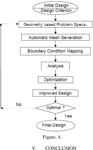
From reading above all the research paper, researchers follow some of basic steps to start their work. The work done for completing their research they have used different software and solver like ANSYS,HYPERWORKS,ABAQUS,LISA and many more used by them. But the procedure is followed as below.
1. Design calculation for the part.
2. Making a CAD model of the part using design software like CATIA V5 importing them into STEP or IGES format.
3. Calculating maximum principal stress generated on the part while static and dynamic loading conditions. 4. Predicting life cycle, safety factor and distortion on the part using GOODMAN's diagram tool using solvers like ANSYS or HYPERWORKS.
5. Optimising design model of the part.
Figure. 4.
V. CONCLUSION
-Studying all the above research work done by researchers to conclude that the work on finding the stress and life cycle of the machine parts are done by researchers. It can be done by experimentation and simulation with the help of advance technical software like Hyperworks. But Experimentation of machine part is post manufacturing process and it require some actual machine part to perform experiments. Whereas, in simulation all this test are carried out on machine part and no need of actual machine part. Most important is that it can be perform before manufacturing process starts. Means we can validate the machine part before it is actually manufactured in factory. Check its lifecycle and durability, make changes in its design to increase its life and strength and then began its manufacturing process. By this way we will not only save our time but also increases the life and quality of product.
VI.
REFERENCES
[1] A.J. Koivo, M.Thoma, E. Kocaoglan and J. Andrade-Cetto (1996),"Modeling and control of excavator dynamic during digging operation", Journal of aerospace engineering .pp 10-18
[2] Alexander Janushevskis, Janis Auzins, Anatoly Melnikovs and Anita Gerina-Ancane (2012) "Shape optimization of mechanical components for measurement systems", Riga Technical University Latvia. pp 243-262.
[3] Allan Ericsson and Jesper Slättengren, " A model for predicting digging forces when working in gravel or other granulated material " 15:th ADAMS European Users Conference, Rome 2000. pp 1-9
[4] Bhaveshkumar P. Patel and J. M. Prajapati (2012), Evaluation of Resistive Force using Principle of Soil Mechanics for Mini Hydraulic
Backhoe Excavator, International Journal of Machine Learning and Computing, Vol. 2, No. 4.pp 368-391.
[5] Bing Kuangl, Zhaolin Liul and Xiaohua Wu (2012), Structural Optimization Design of Swing Arm Based on HyperWork, International Conference on Electronic Packaging Technology & High Density Packaging.
[6] C. P. Motka and Ikbalahemad R Momin, "Development of Backhoe Machine By 3-D Modelling Using CAD Software and Verify The Structural Design By Using Finite Element Method" IJIRST – International Journal for Innovative Research in Science & Technology, Volume 1, Issue 8 pp 49-52.
[7] Emil Assenov, E. Bosilkov, Radoslav Dimitrov and Tzvetan Damianov (2003) University of Mining and Geology “St. Ivan Rilski” Annual, vol. 46, part ІІІ, Mechanization, Electrification and Automation in Mines, Sofia , рр.47-49
[8] Farzin H.Montazersadgh and Ali Fatemi, (2007) Dynamic Load and Stress Analysis of a Crankshaft, The University of Toledo, SAE International.
[9] Fiorenzo Malaguti (1994) "Soil machine interaction in digging and earthmoving automation", Automation and Robotics in Construction Elsevier Science pp 187-191.
[10] Gong Haibin and Su Jian (2011)"Design and finite element analysis of shaking table for fatigue test of high speed train transmission system", Institute of electrical and electronics engineers pp 182-188
[11] K. Thriveni and Dr. B. JayaChandraiah (2013) ," Modeling and analysis of the crankshaft using Ansys software " International Journal of Computational Engineering Research,Vol-3 issue 5 pp 84-89
[12] LucjanWitek,(2015), Fatigue analysis of compressor blade with simulated foreign object damage, Journal of Engineering Failure Analysis, No. 58 pp. 229–237.
[13] M.Behzad, (2008),"A linear theory for bending stress-strain analysis of a beam with an edge crack", Engineering facture mechanics 75 pp 4695-4705.
[14] Michael G. Lipsett ,"Methods for Assessing Dynamic Performance of Shovels", University of Alberta, Edmonton
[15] M. Stavropoulou , G. Xiroudakis and G. Exadaktylos (2013), "Analytical model for estimation of digging forces and specific energy of cable shovel", Coupled Systems Mechanics, Vol. 2, No. 1 pp. 23-51
[16] P Mahesh Babu and K Sreenivas (2014), "Fatigue analysis and design optimization of digger arm" , International journal of mechanical engineering and robotics research. vol 3,No.4 pp 527-532.
[17] P. K. Vaha and M. J. Skibniewski (1993) "Dynamic model of excavator", Journal of aerospace engineering, vol 6(2) pp 148-158
[18] R. J. Deshbhratar1 and Y. R. Suple (2012), "Analysis & Optimization of Crankshaft Using Fem", International Journal of Modern Engineering Research (IJMER), Vol. 2, Issue. 5, pp-3086-3088
[19] R.M. Metkar, V.K. Sunnapwar and S.D. Hiwase (2011)"A Fatigue Analysis And Life Estimation Of Crankshaft", International Journal of Mechanical and Materials Engineering (IJMME), Vol.6, No.3, pp 425-430
[20] Shi Peicheng (2011), "The design of vehicle twist beam rear axle based on structure topology optimization", Institute of electrical and electronics engineers
[21] Vivek Zolekar and Dr. L.N. Wankhade," Finite Element Analysis and Optimization of I.C. Engine Piston Using RADIOSS and OptiStruct " ,Altair technology conference. pp 1-8
[22] W. M. Wan Muhamad, E. Sujatmika, M.R. Idris and S.A. Syed Ahmad (2012) "An Optimization Analysis on an Automotive Component with Fatigue Constraint Using HyperWorks Software for Environmental Sustainability ",World Academy of Science, Engineering and Technology International Journal of Mechanical, Aerospace, Industrial, Mechatronic and Manufacturing Engineering Vol 6, No 8 pp. 1395-1399