http://www.sciencepublishinggroup.com/j/ijssam doi: 10.11648/j.ijssam.20170202.12
Ground Based Laser Torque Effects on Both Passive and
Active Control for LEO CubeSat
Thanaa E. Sharaf-Eldin
1, 2, Nabawia S. Khalifa
2, 31
Electrical. Eng. Department, Faculty of Engineering, Alexandria University, Alexandria, Egypt 2
Basic Sciences Department, Deanship of Preparatory Year- Girls Branch, University of Hail (UOH), Hail, Saudi Arabia 3
Sun and Space Research Department, National Research Institute of Astronomy and Geophysics, Helwan, Egypt
Email address:
[email protected] (T. E. Sharaf-Eldin), [email protected] (N. S. Khalifa)
To cite this article:
Thanaa E. Sharaf-Eldin, N. S. Khalifa. Ground Based Laser Torque Effects on Both Passive and Active Control for LEO CubeSat. International Journal of Systems Science and Applied Mathematics. Vol. 2, No. 2, 2017, pp. 57-63. doi: 10.11648/j.ijssam.20170202.12
Received: March 15, 2017; Accepted: March 27, 2017; Published: April 13, 2017
Abstract:
The objective of this work is to investigate the effects of laser torque on both passive and active control for LEO CubeSat. The investigation is based on the model of the Euler equations for rotational motion. A simple case of spacecraft attitude control problem is considered, in which passive control is performed by accounting only gravity gradient torque, and then active control technique is implemented using PD control and one momentum wheel. The system simulation is conducted using the package of Matlab 7.10-(R2010a). The simulated results show the effect of applying different magnitudes of ground based laser torque on the system stability for passive and active control. Having applied the ground based laser torque onpassive and active control techniques respectively; the obtained results show that the laser torque possesses negative effects
on the system performance for the current study. For passive control, the ground based laser torque has a significant effect where the roll and yaw angles' responses are diverged. However, with active control, the effect of laser torque is limited by a proper PD gains tuned.
Keywords:
LEO Cubesat, Passive Control, Active Control, Euler Equations, PD Control, Ground Based Laser Torque1. Introduction
Nowadays, CubeSats become the most popular space-crafts due to their physical size and weight. They have relative simple hardware requirements for moderate attitude control, which results in an attractive short period of design, low energy and low cost. CubeSats’ specifications are used to help universities and research institutes worldwide to carry out space science and exploration researches.
For extremely accurate satellite positioning and
orientation, both satellite orbital and rotational motion must be modeled. The current work deals with satellite attitude control which plays a significant role to preserve the satellite in its designed attitude. Satellite attitude control systems are divided into two categories: passive and active control systems. Passive systems depend on the natural forces (i. e. gravity gradient, solar radiation pressure, aerodynamics and earth’s magnetic field) for stabilization and control. These methods have been used due to their simplicity and low cost. Nevertheless, they can provide low pointing accuracies and
limited control torques because of their dependability on the gravitational field and the geomagnetic field conditions.
results in highly nonlinear attitude control problem [8] and [9] (Samir (2009) and Vincent (2010)). For control algorithm, the conventional linear controllers; Proportional Derivative (PD), Proportional Integral (PI) and Proportional Integral Derivative (PID) are the commonly choices due to their design and simplicity. The main drawbacks of linear controllers are disregarding the uncertainty in satellite modeling and neglect nonlinear effects. The aforementioned factors lead to long settling time. On the other hand, the nonlinear control techniques include the effect of nonlinear dynamics. Variable structure control designs have attracted some researchers to implement them for attitude control of spacecraft. Particular attention has been given to the sliding mode control design, which has the advantage of reducing the system order to generate the control command. Moreover, the sliding mode presents the system robustness against to the external disturbances taking into consideration the model uncertainties [1] (E. Abdualhamitbilal et al.).
Recently, the possibility of using laser power for space applications became of great interest. There are several advantages of using lasers over other techniques of beamed power; the laser receiver is the solar array, so no new receiver technology is needed. Moreover, space laser beam suffers a less amount of atmospheric attenuation compared with the other beamed power applications. Also, it can be adjusted to be safe in use (i. e. no damage in the satellite surface) (El-saftawy et al. (2007), El-(El-saftawy and Makram (2004), Geoffery (1994) and Khalifa (2009)). With the intention of overcoming some disadvantages of the traditional attitude actuators, the issue of this work is to investigate the feasibility of using different ground based laser torques for passive and active attitude control of low Earth orbit CubeSats.
This paper is organized as follows: section “II” reviews the Euler equations of rotational motion, where the disturbing torques is that due to gravity gradient while the other disturbance will be ignored. The ground based laser torque of different magnitudes is worked out as control torque. Section III illustrates the system simulation and results for both passive and active control using the package of Matlab 7.10-(R2010a). Passive control will be studied first under the effect of gravity gradient only, and then in presence of both laser and gravity gradient torques. Active control technique based on PD controller is implemented for a momentum biased cubesat, which is supported by one reaction wheel. Then simulation is conducted to illustrate the effect of laser torque with different power range on response of yaw and roll angles. The conclusions and suggestions for future work are found in section IV.
2. System Modeling
2.1. Reference Frames
In this section, the three main reference frames are explained in the following subsections [4], [8] and [9] (Karla
(2009), Samir (2009) and Vincent (2010)):
2.1.1. Earth Centred Earth Fixed (ECEF) Frame
It is an Earth centred coordinate system which rotates relative to the Earth Centred. Its unit vectors are: which is extended to to the zero latitude and longitude point (i. e. the intersection of the Equator and the prime meridian passing through Greenwich, UK), is the earth spin axis which is pointing towards the celestial North Pole and completes the right- handed system.
2.1.2. Earth Centred Inertial (ECI) Frame
It is fixed with respect to inertial space and centered at the
Earth’s center of mass with unit vectors: directed towards
the vernal equinox, directed towards the ecliptic pole and
completes the right- handed system.
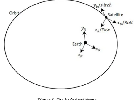
2.1.3. The Body Fixed Frame
It is centered at the center of mass of the satellite with unit
vectors: is the pointing towards the Earth’s center (Yaw
axis), is directed normal to the satellite orbital plane (Pitch
axis) and completes the right- handed system (Roll axis)
As shown in figure 1.
It’s worth noted that, the rotation between the body-fixed frame and ECI is considered to be the satellite attitude which is the focus in attitude control problems.
Figure 1. The body fixed frame.
2.2. Satellite Rotational Dynamics
2.2.1. Equations of Motion
For a momentum biased satellite in which the principle moments of inertias are aligned through the body fixed frame, the linear differential equations of motion are (Sidi, 1997; Wertz, 1978, Hsu et al., 1965):
4
(1)
3 (2)
where , and are the components of disturbing
torques and " , " and " are the components of control
torques. The angles , and are the Euler angles which
describe the satellite rotations around its axes: represents
rotation around , represents rotation around and
represents rotation around . The term is the angular orbital
velocity of the satellite which is called the orbital rate or
frequency. , and are the angular momentum
components of the momentum wheels in the body fixed frame. , and are the components of moment of inertia tensor.
In the previous system of equations (1-3), it is noticed that the gravity gradient moment terms are included in the right hand where they weren’t considered as disturbing or control torques. Moreover, the roll and yaw motions are coupled and must be solved simultaneously. While the pitch motion, which is given by eqn. 2, is uncoupled with that of roll and yaw. So, the pitch attitude is controlled by a torque capabilities of a momentum
wheel, , which is set initially at some nominal biased value
and it may be changed owing to the external disturbances acting
about the axis however the other angular momentum
components are assumed to be dumped [2] and [7] (Ouhocine et al., 2004 and Esmailzadeh et al., 2011).
2.2.2. Laser Control Torque
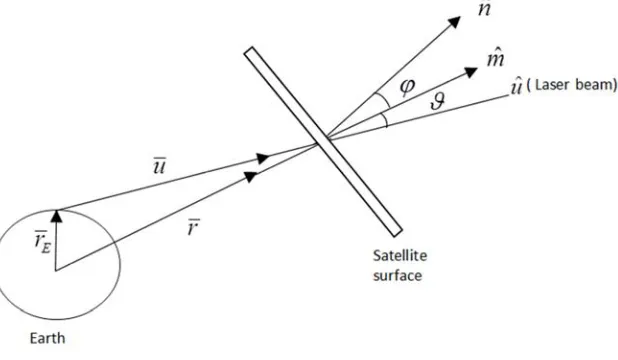
The control torque is considered to be that produced by a laser beam that was fired from a ground station towards the satellite. The components of laser torque in the ECI frame are given by [6] (Khalifa, 2012):
& ' ( cos , - . / . / 01 (4)
& ' ( cos , - . / . / 01 (5)
& ' ( cos , - . / . / 01 (6)
where 2 is the laser beam intensity at the satellite surface, 3 is
the speed of light, ( is a function of thermo-optical properties
of the satellite surface, , is the angle between the incident
unit vector /4 and the satellite surface normal and .5 is the unit
vector directed from the spacecraft's center of mass to the
element of satellite projected area 01. The unit vector /4 can
be transformed to the body fixed frame as follows:
/4 1 /4 (7)
Where 1 is the rotation matrix and /4 is the unite vector
of laser beam incident direction in the ECI as shown in figure
2. The components of the unit vector /4 are given by (NS.
Khalifa, 2012):
/ 6 cos Ω cos ( 8 sin Ω sin ( 8 cos :
;<cos =>cos ? (8)
/ 6 sin Ω cos ( 8 cos Ω sin ( 8 cos :
;<cos =>sin ? (9)
/ 6 sin ( 8 sin : ; sin => (10)
where
Ω
is longitude of the ascending node, β is argumentof perigee,
υ
is the true anomaly, i is the inclination,a
isthe semi-major axis and
e
is the eccentricity.;< <B CABCAD@AEFGDHIJ D⁄ (11)
; @A<BCAD
<B CABCAD EFGDHIJ D⁄ (12)
where
a
e is the Earth’s equatorial radius,f
e′
is the Earth’sflattening,
ϕ
gis the geodetic latitude, his the height abovesea level and ? is the sidereal time.
Figure 2. The laser intensity delivered to the satellite surface.
3. System Simulation
The model is implemented on a hypothetical 3U cubesat in a
for analyzing the passive and active control under the effect of gravity gradient and laser torques in different cases.
Table 1. The satellite orbit.
Orbit Sun-synchronous
Inclination 98o
Altitude 600 Km
Period 5732 s
Table 2. The input parameters.
{ , , } {10 o, 0 o, 0 o}
{ , , } { 0.025, 0.025,0.05) Kg m
{ℎ , ℎ , ℎ } { 0, 0.0035,0) Kg m /s
0.0010764 rad/s
3.1. Passive Control
For passive control, it is assumed that there were no momentum devices and control torque. In this section two cases of passive control will be simulated; the purely passive control under gravity gradient torque only then in presence of laser torque.
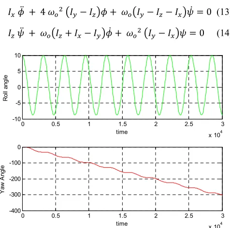
3.1.1. Purely Passive Gravity Gradient Attitude Control In this type of control, the other natural disturbances torques are ignored. Then the equations of roll and yaw motions (eqs. 1 and 3) will be reduced to the following form:
+ 4 − + − − = 0 (13)
+ + − + − = 0 (14)
Figure 3. Response of roll and yaw angles using the passive attitude control.
The responses of the roll and yaw angles were illustrated in figure 3. The performance of roll angle shows that the motion is un-damped oscillation i. e. the satellite is marginally stable for roll angle. However, the yaw motion shows a divergent behavior.
3.1.2. Laser Passive Attitude Control
Having applied laser torque seeking for controlling the satellite behavior, the equations of roll and yaw motions in (eqs. 1 and 3) will be reduced to:
+ 4 − + − − = & (15)
+ + − + − = & (16)
For the purpose of this analysis, the following postulates are applied:
1.The radiation fall normal to the satellite surface.
2.The satellite surface is considered to be perfectly
reflecting surface. So, the laser force will be duplicated.
3.(3-2-1) Euler rotation is assumed with ψ being the first
angle of rotation, θ being the angle of the second rotation and φ being the angle of the third rotation. Based on the previous postulates and applying a laser torque of about 10 kw power, the components of laser torque are given by:
& = cos −4.1 × 10BX cos + 1.8 × 10BZsin ) +
+ cos cos 1.4 × 10BX+ 3.9 × 10BX sin )
+ 1.6 − 3.4 × 10B] 2:^ ) sin )
+ sin cos 3.4 × 10B]− 1.6 × 10BZ sin ) + 3.9 × 10BX+ 1.4 × 10BX 2:^ ) sin )
& = cos −3.4 × 10B]cos − 3.9 × 10BXsin ) +
+ cos −3.9 × 10BXcos − 4.1 × 10BXsin + 3.4
× 10B]sin ) +
+ sin −4.1 × 10BX+ 3.9 × 10BXcos sin − 3.4
× 10B]sin sin )
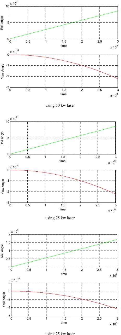
The responses of the roll and yaw angles using different magnitude of laser torque as passive control in addition to the gravity gradient are illustrated in figure 4.
using 25 kw laser
0 0.5 1 1.5 2 2.5 3
x 104 -10
-5 0 5 10
time
R
o
ll
a
n
g
le
0 0.5 1 1.5 2 2.5 3
x 104 -400
-300 -200 -100 0
time
Y
a
w
A
n
g
le
0 0.5 1 1.5 2 2.5 3
x 108 0
2 4 6x 10
7
time
R
o
ll
a
n
g
le
0 0.5 1 1.5 2 2.5 3
x 108 -15
-10 -5
0x 10
13
time
Y
a
w
A
n
g
using 50 kw laser
using 75 kw laser
using 75 kw laser
Figure 4. Response of roll and yaw angles using the passive attitude control under the effect of different magnitude of laser torque.
The obtained results, Fig. 4, show a divergent behavior for both roll and yaw motions under the effect of different laser torque magnitudes. Therefore, attitude stability cannot be achieved by using passive laser control in existence of
gravity gradient only
.
Then introducing of damping controlis considered to be necessary. In the next subsection, a study of active control based on PD controller, moreover the effect of laser torque on the system performance will be explained.
3.2. Active Control
Active control technique is commonly used for damping. The basic idea dominating any damping system is to afford additional dynamic elements within a system, and to provide suitable coupling between the system variables in order to obtaining largest possible damping of satellite angular motion. Consequently, it is assumed that the satellite was equipped with a momentum wheel to provide an inertial stability about the pitch axis. The wheel angular momentum components are given in table 2.
4. Controller Design
In this work, the implemented control algorithm here is PD controller. In comparison to the other alternatives control algorithm, the Proportional Derivative (PD) controller is chosen because it can be designed using classical control theory and therefore gain selection is relatively intuitive. Moreover, the PD controller does not depend on linear equations of motion and therefore is capable of large angle manoeuvres by incorporating the nonlinear dynamics (Francois-Lavet, 2010).
The control command equation is given by:
" _< _ " _< _
Where _< and _ are the proportional gains which are
selected by proper tune in order to achieve desired response. The proportional and derivative gains are given in Table 3:
Table 3. The parameters of PD controller.
_< 0.6 × 10BZ
_ 44.5 × 10BZ
The simulation for active control will be conducted first for PD and momentum wheel, and then the effect of laser torque will be considered.
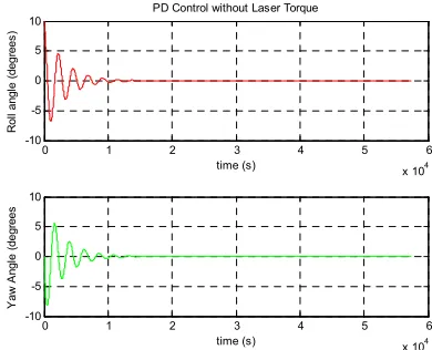
4.1. PD Controller for a Momentum Biased Cubesat Without Laser Torque
Assuming that one momentum wheel is added to the satellite equipment to provide inertial stability about the pitch axis. The gains of PD controller are tuned manually to optimize the responses of the roll and yaw angles.
0 0.5 1 1.5 2 2.5 3
x 108 0
5 10x 10
7
time
R
o
ll
a
n
g
le
0 0.5 1 1.5 2 2.5 3
x 108 -3
-2 -1
0x 10
14
time
Y
a
w
A
n
g
le
0 0.5 1 1.5 2 2.5 3
x 108 0
5 10x 10
7
time
R
o
ll
a
ng
le
0 0.5 1 1.5 2 2.5 3
x 108 -3
-2 -1
0x 10
14
time
Y
a
w
A
n
g
le
0 0.5 1 1.5 2 2.5 3
x 108 0
0.5 1 1.5
2x 10
8
time
R
o
ll
a
n
g
le
0 0.5 1 1.5 2 2.5 3
x 108 -6
-4 -2 0 2x 10
14
time
Y
a
w
A
n
g
Figure 5. Responses of yaw and roll using PD controller for momentum biased cubesat.
It observed from Fig. 5 that the stability of the CubeSat is assured. The results show that response in roll and yaw angles starting from the initial position (as in Table 2), are able to converge to zero in about two orbit time. The steady state error is zero in both roll and yaw.
4.2. PD Controller with Laser Effect for a Momentum Biased Cubesat
The simulation is carried out using different magnitudes of laser torque which are as given in table 3. The responses of the roll and yaw angles using different magnitude of laser torque using PD controller were illustrated in figure 6.
Figure 6. Response of yaw and roll using PD controller with different magnitude of laser torque.
It can be shown in Fig. 6 that the effect of laser torque can be summarized as follows:
1.The laser torque increases the steady state errors in both
roll and yaw angles. It is obvious it has more significant effect in yaw angle than rol angle; this is expectedly due to larger negative component of laser torque in z-axis than x-axis.
2.Having increased the magnitude of laser torque, the
steady state errors in both axes are increased.
3.It is noted that the laser torque has no effect on system
stability or the time response of system.
5. Conclusion
For this simple case of study, authors investigated and assessed the effects of ground based laser torque with different magnitudes on both passive and active control. The obtained results illustrated that the satellite stability cannot be realized on using gravity gradient torque and laser torque for passive control.
However with PD active control biased on momentum wheel, the results show that the stability is assured and laser
0 1 2 3 4 5 6
x 104 -10 -5 0 5 10 time (s) R o ll a n g le ( d e g re e s )
PD Control without Laser Torque
0 1 2 3 4 5 6
x 104 -10 -5 0 5 10 time (s) Y a w A n g le ( d e g re e s
0 1 2 3 4 5 6
x 104 -10 -5 0 5 10 time (s) R o ll a n g le ( d e g re e s )
PD Control with Laser Power of 25 kW
0 1 2 3 4 5 6
x 104 -10 -5 0 5 time (s) Y a w A n g le ( d e g re e s
0 1 2 3 4 5 6
x 104 -10 -5 0 5 10 time (s) R o ll a n g le ( d e g re e s )
PD Control with Laser Power of 50 kW
0 1 2 3 4 5 6
x 104 -15 -10 -5 0 5 time (s) Y a w A n g le ( d e g re e s
0 1 2 3 4 5 6
x 104 -10 -5 0 5 10 time (s) R o ll a n g le ( d e g re e s )
PD Control with Laser Power of 75 kW
0 1 2 3 4 5 6
x 104 -15 -10 -5 0 5 time (s) Y a w A n g le ( d e g re e s
0 1 2 3 4 5 6
x 104 -10 0 10 20 time (s) R o ll a n g le ( d e g re e s )
PD Control with Laser Power of 100 kW
0 1 2 3 4 5 6
torque has no effect on both system stability and system time response.
Increasing
The laser torque magnitudes have the consequences of increasing the steady state errors in the response of roll and yaw angles. The effect of laser torque is more significant in yaw angle response than roll angle response.
Future work The authors aim to:
1.Study system stability under the effect of laser torque.
2.Study laser active control by replacing the linear PD
controller with the variable structure control algorithm.
3.Study the problem in presence of different disturbing
torques (e. g. aerodynamics, solar radiation, etc), more than one reaction wheel and magnetic torquer.
4.Study the problem in the quaternion frame.
References
[1] Abdualhamitbilal and E. M. Jafarov, 2006, “Performances comparison of linear and sliding mode attitude controllers for flexible spacecraft with reaction wheels, proceedings of the 2006 international workshop on variable structure system. Alghero, Italy, 2006.
[2] C. Ouhocine, M. N. Filipski, S. B. Mohd Noor and M. R. Ajir,
“Small Satellite Attitude Control and simulation”, jurnal Mekanikal, Bil.17, 2004.
[3] J. C. Hsu, Y. S. Lim and A. U. Meyer, “on active control of satyellites”, IEEE Transactions on Military Electronics, 1965. [4] K. Vega, “Attitude Control System for CubeSat for Ions,
Neutrals, Electrons and MAGnetic Field (CINEMA)”, MSc. Thesis, UNIVERSITY OF CALIFORNIA, BERKELEY, 2009.
[5] M. J. Sidi, “Spacecraft Dynamics”, Cambridge University Press, 1997.
[6] N. S. khalifa, “Effect of an Artificial Radiant Force on the Spacecraft's Orbit”, Phd. Thesis, Cairo university, 2009. [7] R. Esmailzadeh, H. Arefkhani and S. Davoodi, “Active
control and attitude stabilization of a momentum-biased satellite without yaw measurements, IEEE, Electrical Engineering (ICEE), 19th Iranian Conference, 2011.
[8] Samir Rawashdeh” PASSIVE ATTITUDE STABILIZATION FOR SMALL SATELLITES”, Msc. Thesis, University of Kentucky, Kentucky, 2009.
[9] Francois-Lavet, “Study of passive and active attitude control systems for the OUFTI nanosatellites”, Msc. Thesis, University of Liège, 2010.