Iranian Journal of Electrical and Electronic Engineering, Vol. 14, No. 4, December 2018 342
Dynamic
Modeling
and
Control
of
Grid-Connected
Photovoltaic
Systems
based
on
Amplitude-Phase
Transformation
M. A. Azghandi*, S. M. Barakati*(C.A.) and B. Wu**
Abstract: A voltage source inverter (VSI) is widely used as an interface for distributed generation (DG) systems. However, high-power applications with increasing voltage levels require an extra power converter to reduce costs and complications. Thus, a current source inverter (CSI) is used. This study presents a precise phasor modeling and control details for a VSI-based system for DG and compares it with a CSI-based system. First, the dynamic characteristics of the system based on amplitude-phase transformation are investigated via small signal analysis in the synchronous reference frame. Moreover, the performance of the grid-connected system is determined by adopting the closed-loop control method based on the obtained dynamic model. The control strategies employ an outer active-power loop cascaded with an inner reactive-power loop, which the inner loop is a input single-output system without coupling terms. The sensitivity analysis of the linearized model indicates the dynamic features of the system. The simulation results for the different conditions confirm proposed model and design of the controller.
Keywords: Current Source Inverter (CSI), Distributed Generation (DG), Photovoltaic (PV), Eigenvalue Analysis, Voltage-Source Inverter (VSI).
1 Introduction1
N recent years, photovoltaic (PV) systems have become popular because of the increasing environmental effects of fossil-fuel use and the energy security issue. PV generators can be used to recharge batteries, connect directly to a power grid, or drive electric motors without batteries [1]. Renewable-energy sources can produce DC current, whereas the output current must be AC to connect to a grid. Therefore, inverters are required to control power conversion between a generator and a network [2]. The topologies of electronic power converters are one of the main components of PV systems. A comprehensive review of
Iranian Journal of Electrical and Electronic Engineering, 2018. Paper first received 30 November 2017 and accepted 18 March 2018. * The authors are with the Faculty of Electrical and Computer Engineering, University of Sistan and Baluchestan, Zahedan, Iran. E-mails: [email protected] and [email protected]. ** The author is with the Department of Electrical and Computer Engineering, Ryerson University, Toronto, Canada.
E-mail: [email protected]. Corresponding Author: S. M. Barakati.
the power converters for PV applications is presented in the literature [3, 4]. Current studies related to PV systems are generally based on voltage source inverters (VSIs). VSIs use a capacitor to connect the PV generator to a grid with a constant voltage and have lower energy losses than current source inverters (CSIs), which use an inductor. In high-power applications, a CSI may be preferable to connect PV systems to a power grid because a CSI reduces the requirements related to step-up transformers and receives the smoother current from PV modules than a VSI. A particular type of PV module can produce a voltage of up to several hundred volts [5].
Recently, researchers have focused on the dynamic model, stability, and control approaches of single-phase and three-phase, single-stage PV systems [6-18]. The effect of grid impendence variations on the closed-loop stability of a single-phase PV system with an appropriate controller design was investigated in [6]. The pulse-width modulation (PWM) control strategy for a grid-connected PV system with its control loops and functions was presented in [7]. The behavior of a PV system, along with the maximum power point tracking
I
Iranian Journal of Electrical and Electronic Engineering, Vol. 14, No. 4, December 2018 343 approach (MPPT), was studied in [8]. A control method
was proposed in [9] to separate PV system dynamics from the distribution network and load. Active and reactive power control of a grid-connected PV system that used a digital control based on the changes in the VSI voltage phase in comparison with network voltage has been investigated in [10]. Dynamic properties of a grid-connected PV system was analyzed in [11] considering voltage-fed and current-fed VSI. Modeling guidelines and a benchmark for three-phase, single-stage PV Systems were presented in [12]; further parameter selection and control tuning issues were investigated. In [13], the performance of a CSI connected to a single-phase network with a boost converter was examined. An analysis of a transformer-less, grid-connected, and three-phase PV system based on CSI was presented in [14]. The model and control for a CSI-based PV system, along with the transient and steady state performance of the system, were presented in [15]; the performances of a VSI-based system and a CSI-based system were also studied. In [16] an overview about micro-grid structure and control schemes of power converters in AC micro-grids were carried out. A two-stage control structure, concluding disturbance estimator-based current-mode controller for grid-tied PV systems is proposed in [17]. A digital predictive current controller for a single-phase grid-side power electronics converter employed in PV systems is presented in [18] that minimize the sensitivity to any parameter variation via a disturbance estimator.
The literature survey indicates that researchers rarely perform a comprehensive comparison between CSI-based and VSI-CSI-based PV systems. A division of the control strategies with respect to the reference frame they are implemented in is synchronous reference frame control, stationary reference frame, and natural frame. In the synchronous reference frame control, the currents and voltages are transformed into a reference frame that rotates synchronously with the grid voltage using the
abc → dq module, and the control variables become DC values. The cross-coupling terms are the major drawback of the control structure implemented in dq
frame.
In other literatures employing synchronous reference frame, only abc → dq module is used in order to modeling and control of the system. Dealing directly with phasors is more straightforward than dealing with
dq components. In this study, the phasor dynamic modeling and control approach for a three-phase grid-connected PV system is presented for VSI and CSI in the synchronous reference frame using the abc → amplitude-phase module. Both inverters operate with an identical rating and transfer maximum power from a PV generator to a power system at desired reactive power. These two systems are compared under various conditions by considering the eigenvalue sensitivity analysis of the CSI- and VSI-based systems with regard to the network parameter deviation.The control
structure of the system contains an outer loop cascaded with an inner loop. The external loop is responsible for active power while the fast internal loop is responsible for reactive power only. The inner loop is a single-input single-output system without cross-coupling terms, and amplitude or phase of the voltage and the current can be adjusted via only one control variable. The time-domain simulationsindicate the appropriate control and robust performance of the systems under different conditions. The rest of this paper is organized as follows. Section 2 introduces the structure of the studied systems. The dynamic modeling and design of an appropriate controller for a VSI-based PV system are presented in Section 3. Section 4 discusses the modeling and control for a CSI-based PV system. Section 5 compares the performances of a CSI-based PV system and a VSI-based system. Section 6 concludes the study.
2 Structure of the Grid-Connected PV System
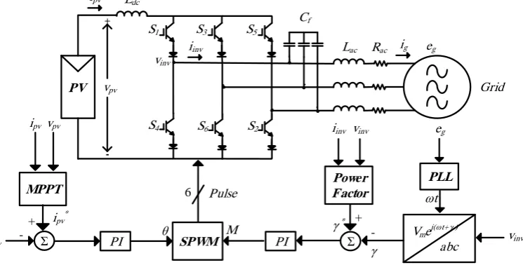
Fig. 1 presents a schematic diagram of a three-phase grid-connected PV system based on the VSI. The PV system contains Np parallel strings composed of Ns
series modules and connected to a VSI via a capacitor
Cdc. The VSI switches are controlled using the
sinusoidal PWM strategy. The inverter is connected to a power system through resistance Rac and inductance Lac.
Rac includes the total of resistances of the switches
on-state, filter, and grid, whereas Lac combines inductances
of the filter and the grid. Fig. 2 presents the structure of a CSI-based PV system. The PV generator is connected to a CSI via inductance Ldc. Rac and Lac are grid
resistance and inductance, respectively.The output filter
Cf absorbs the switching harmonics to produce a
high-quality sinusoidal current with an acceptable THD at the grid interface.
3 Dynamic Modeling and Control of the VSI-based PV System
In this section, an average dynamic model for a grid-connected VSI-based PV system is obtained. The system control approach is then determined based on this model.
3.1 VSI-based System Modeling
The output power of a solar cell varies with the amount of available irradiation and the temperature. The relationship between the current and the voltage of a PV array is
( , , )
pv pv
i f v S T (1)
where ipv and vpv are the PV array current and voltage,
respectively; S denotes irradiation, and T indicates the ambient temperature. More details for I-V characteristics of the PV array are referred to [19]. An appropriate and reliable approach to determine the performance characteristics of a PV array was proposed
Iranian Journal of Electrical and Electronic Engineering, Vol. 14, No. 4, December 2018 344 PV S1 S4 S3 S6 ac L Cdc pv v + -ipv S5 S2 ac
R eg
Grid vinv. . . iinv eg SPWM Σ φ φ* PI + -M MPPT vpvipv PI θ Σ vpv* 6 Pulse +
-.
.
.
ig PLLImej(ωt+ φ)
abc iinv ωt vpv vinv Power Factor iinv
Fig. 1 Schematic diagram of a grid-connected PV system based on the VSI.
eg
SPWM Σ
γ γ *
PI
+
-M MPPT
ipvvpv
PI θ
Σ
ipv*
6 Pulse
+
-PLL
Vme j(ωt+ γ )
abc vinv
ωt ipv iinv Power Factor vinv PV S1 S4 S3 S6 ac L Ldc pv v + -ipv S5 S2 ac
R eg
Grid vinv . iinv Cf . . . . .
.
.
.
.
.
.
igFig. 2 Schematic diagram of a grid-connected PV system based on CSI.
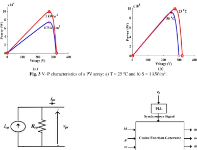
in [20]. A numerical method for modeling PV array based on their performance characteristics was developed in [21]. This method aims to fit the mathematical I–V equation into the experimental remarkable points of a practical array. Figs. 3 indicate the voltage–power characteristics of a PV array under various radiation levels and temperatures.
The linearized equivalent circuit of a PV generator can be modeled as a parallel current source with a resistance, as shown in Fig. 4 [22]. In the circuit shown in Fig. 4, ipv and vpv represent the terminal current and
voltage of the PV generator, respectively. Ieq and Req are
given by
e ( )
s eq p i
s p s
q s p
p
R
i N I
R R
N
R R R
N
(2)
where Ii is the output current, Rp denotes the parallel
resistance, and Rs indicates the series resistance of the
PV module. The differential equation of the PV output DC current can be written as
pv
pv dc dc
dv
i C i
dt
(3)
where idc is the input current of the VSI. The AC-side
equations are formulated as follows:
cos( )
2
pv inv
v
v M t (4)
mcos( )
g
i I t (5)
cos( )
g m
e E t (6)
where vpv is the output voltage of VSI, ig denotes the
grid current, φ is the initial phase of ig, eg indicates the
grid voltage, ω signifies the angular frequency, M
Iranian Journal of Electrical and Electronic Engineering, Vol. 14, No. 4, December 2018 345
(a) (b)
Fig. 3 V–P characteristics of a PV array: a) T = 25 ºC and b) S = 1 kW/m2.
ipv
ieq
+
-vpv
Req
Cosine Function Generator PLL
eg
Synchronous Signal
M
θ ω
ma
mb
mc
Fig. 4 The equivalent circuit of a PV generator. Fig. 5 The method for producing modulation signals.
represents the amplitude index of the PWM, and θ denotes the PWM phase index. The three-phase current and voltage are considered balanced with positive phase sequences. The magnitude, phase, and frequency of the VSI output voltage can be obtained via modulation signals.
cos( ) cos( 120 ) cos( 120 ). a
b c
m M t
m M t
m M t
(7)
To match the phase of the modulation signals with the phase of the reference signal as well as to track the reference frequency, a phase-locked loop (PLL) technique is adopted [23]. Fig. 5 describes the method for producing modulation signals using the obtained amplitude and phase indices of modulation as well as the synchronous signal (ωt) determined by PLL. By disregarding inverter losses, the output power will be equal to the input power. Thus,
m 3
cos( ). 4
pv
i MI (8)
The output voltage of VSI can be expressed as
.
g inv ac g ac g
di
v R i L e
dt
(9)
Using (1)–(9), the VSI-based PV system can be
described by the following nonlinear differential equations:
m
3 1
cos( ) ( )
4
pv
pv
dc dc
dv MI
f v
dt C C (10)
m cos( ) cos( )
2
pv m ac
m
ac ac ac
Mv R
dI E
I
dt L L L (11)
sin( ) sin( ) .
2
pv m
ac m ac m
Mv E
d
dt L I L I
(12)
The complete dynamic model for the VSI-based system is characterized by two inputs, two outputs, and three state variables, as shown in Fig. 6.
In the frequency domain, the relationships between the inputs and the outputs of the linearized system are as follows:
( ) ( ) ( )
( ) ( ) ( )
pv pv
v v
pv M
M
v s G M s G s
s G M s G s
(13)
where vpv
M
G is the transfer function from M to vpv,
pv
v
G denotes the transfer function from θ to vpv, GMφ
indicates the transfer function from M to φ, and Gθφ
represents the transfer function from θ to φ. Also, s represents complex frequency and both damping phenomenon and sustained oscillation phenomenon are considered.
Iranian Journal of Electrical and Electronic Engineering, Vol. 14, No. 4, December 2018 346
Inputs U Outputs Y
.
.
.
State Spaces X
M
θ
vpv
φ vpv
Im
φ
Fig. 6 Inputs, state variables, and outputs of the VSI-based system model.
θ
Gθ Vpv
Σ +
-GMVpv
-Feedforward
Σ + + DC Side
or Active Power
Control
vpv*
M
θ*
vpv*
1 1
i p
k k
s +
GM φ
Σ +
-Gθ φ
-Feedforward
Σ + + AC Side
or Reactive Power
Control
φ*
θ
M* φ*
M kp2+ksi2
(a) (b)
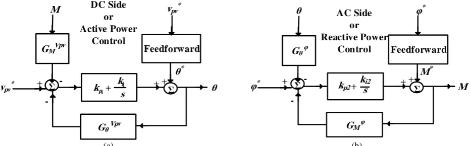
Fig. 7 The control structure of the grid-connected system: a) PV generator voltage control and b) VSI power factor control.
3.2 VSI-based Control System
In the synchronous reference frame, the control variables become DC values and controlling can be easier achieved. The control strategy consists mainly of two cascaded loops; fast internal active-power loop, and external reactive-power loop.
The control system adjusts the inverter switching so that the VSI injects the maximum power into the grid in the desired power factor (often a unity power factor) [12]. The modulation-phase index θ is determined by controlling the PV generator output voltage to track the voltage that corresponds to the maximum power point. The power output of a solar cell is dependent on solar irradiation, ambient temperature, and external loads. The power point tracking seeks the voltage and current conditions that maximize the PV output power. Various MPPT approaches have been presented in different studies [24-26].
The phase of the VSI output current φ is also controlled by the modulation amplitude index M. Thus, the inverter works in the unity power factor. φ must follow θ, and the two systems interactively affect each other. Thus, the controllers must be designed in such a way that the dynamics of the two systems are independent of each other. Moreover, the controller must provide an appropriate phase margin for the robustness of the system. The feedforward control of the system can also improve control performance. The control structure of the system is illustrated in Fig. 7.
vpv* is the reference value of PV array voltage and
determined through MPPT. Furthermore, φ* is the
reference value of the grid current phase angle and determined by θ. Generally, φ*=θ- tan-1(P* ̸ Q*),
where P* and Q* are the reference values for the active
and reactive power of the inverter, respectively. The feedforward terms are calculated via steady-state equations of the system, so that θ*= 0.5sin-1(4L
acωP* ̸
3Em2) and M*=4LacωP* ̸(3Emvpv*sinθ*).
The AC-side controller shapes the phase angle of the inverter output current via the modulation-amplitude index. Furthermore, the modulation-amplitude index determines the amplitude of the inverter output voltage. Accordingly, regulating bandwidth and damping of AC-side control structure improves the quality of the inverter output voltage, while the low-pass filter Lac
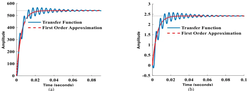
reduces THD of the current injected into the grid. To design appropriate controllers, Gθvpv and GMφ are
approximated using first-order transfer functions, as indicated in Fig. 8. Several methods are available for reducing the order of a system transfer function. The basic idea of approximating the first-order system is based on a “half rule”. In the first step, the time constant of the first-order system is approximated as the sum of time constants of poles (with the positive sign) and zeros (with the negative sign) of the original system. The time constant of the first-order system is modified so that it’s settling time approaches to settling time of the original system.
The first-order transfer functions and the PI controllers are as follows:
Iranian Journal of Electrical and Electronic Engineering, Vol. 14, No. 4, December 2018 347
(a) (b)
Fig. 8 First-order transfer function approximation: a) Time response of vpv
G and its first-order approximation for unit step input and b) Time response of GMφ and its first-order approximation for unit step input.
( ) 0
1 1 1
( ) ( ) ( ) 1 ( ) pv M s v pv
c P I
v s
G s
s
G s k k
s
(14)
( ) 0
2 2 2
( ) ( ) ( ) 1 ( ) . s M
c P I
s
G s
M s
G s k k
s (15)
From (14) and (15), the closed-loop transfer functions of the two aforementioned systems can be determined as follows:
1
1
1
1 1 1 1
1
1 2
1
1
(1 )(1 )
( ) pv P I I v
I P I P
k
k p s s
k p
L
s k k p s k k
(16) 2 2 2
2 2 2 2
2
2 2
2
1
(1 )(1 )
. ( ) P I I M
I P I P
k
k p s s
k p
L
s k k p s k k
(17)
By considering a typical second-order control system as ωn2̸ (s2+2ζωn+ωn2), the relations below can be
adopted to obtain the appropriate design parameters:
1 1
1
1 1 1
2 1 1 2 n I P I n P k k
k k p
(18)
2 2
2
2 2 2
2 2 2 2 n I P I n P k k
k k p
(19)
where ωndenotes the natural frequency, and ζ indicates
the damping ratio of the system. In the frequency domain, the relationships between the bandwidth ωb and
the phase margin ϕm of the system with the parameters
of the second-order system are as follows [27]:
0.01 . 1.961 1.8508 m b n (20)
4 Modeling and Control of the CSI-based PV System
Fig. 2 illustrates how the CSI receives the maximum power from a PV generator and delivers it to the grid in an acceptable power factor. The PV output current is controlled by the PWM phase index θ to achieve the current that corresponds to the maximum power ipv*.
Furthermore, the voltage and current of the CSI must be in phase to control the reactive power. The phase angle of the CSI output voltage γ is controlled by the PWM amplitude index M. Generally,
γ* = θ - tan-1(P* / Q*), where P* and Q* are the
reference values for the active and reactive power of the inverter, respectively. The AC-side controller shapes the phase angle of the inverter output voltage via the modulation amplitude index. Furthermore, modulation amplitude index determines the amplitude of the inverter output current. Accordingly, regulating bandwidth and damping of the AC-side control structure improves the quality of the inverter output current, while the low-pass filter Cf reduces THD of the voltage
at the PCC. The equations related to the grid-connected CSI based PV system can be expressed as follows:
pv
pv dc dc
di
v L v
dt
(21)
cos( )
inv pv
i Mi t (22)
mcos( )
f
C
v V t (23)
f
C
inv f g
dv
i C i
dt
(24)
f
g
C g g
di
v Ri L e
dt
(25)
Iranian Journal of Electrical and Electronic Engineering, Vol. 14, No. 4, December 2018 348 where vdc denotes the input voltage of the CSI, ipv
indicates the output current of the inverter, and vcf
represents the capacitor filter voltage. The magnitude, phase, and frequency of the CSI output current are obtained via modulation signals. Therefore, the CSI-based PV system can be described by the following nonlinear differential equations:
3 1
cos( ) ( )
2
pv m
pv
dc dc
di MV
g v
dt L L (26)
cos( ) cos( )
pv
m m
f f
Mi
dV I
dt C C (27)
sin( ) cos( )
pv m
f m f m
Mi I
d
dt C V C V
(28)
cos( ) cos( ) ac
m m m
m
ac ac
R
dI V E
I
dt L L L (29)
sin( ) sin( ) .
m m
ac m ac m
V E
d
dt L I L I
(30)
The complete dynamic model for the CSI-based system is characterized by two inputs, two outputs, and five state variables, as shown in Fig. 9. It is worth mentioning that the CSI control structure is as same as the VSI.
5 Comparative Performance Evaluation of the CSI-based System with the VSI-CSI-based System
This section presents a comparison of the performances of a CSI-based PV system and a VSI-based PV system.
5.1 PV System Based on the VSI
To validate the appropriate modeling and evaluate the proposed control system, the system is simulated in MATLAB environment. A PV panel type SPR-305-WHT is used in the simulations. The PV array of a VSI-based system contains 66 parallel strings and 5 series modules. The grid-connected PV system parameters are summarized in Table 1.
The selected phase margins must be as large as possible to increase system robustness against disturbance. The phase margins of the AC-side and DC-side control loops are 60 degrees and 70 degrees, respectively. To design the controller for the partial decoupling of the two-input and two-output control structure (Fig. 7), the bandwidth of the selected AC-side (reactive power control) is several times higher than that of the DC-side (active power control). The bandwidth of the reactive power control loop must be sufficiently high to obtain a fast response. However, increasing the bandwidth raises the total harmonic distortion of the current injected into the grid.
We choose kI1 = 0.055 and kI2 = 46.5 in the simulation
of the VSI-based system based on the
. ipv
. Vm
. γ . Im
. φ State Spaces X
Inputs U M
θ
ipv
γ
Outputs Y
Fig. 9 Inputs, state variables, and outputs of the CSI-based system model.
Table 1 System Parameters.
fs [Hz]Cdc [F]Ldc [H] Lf [H] Cf [F] Rac [Ω] Lac [H] Eg [V]
51×50 10−3 10−3 5×10⁻⁵ 5×10⁻⁵ 5×10⁻³ 10−4 120
preceding explanations. At the beginning of the simulation, irradiation S is 0.75 kW/m2, T is 25 ºC, and the voltage of the maximum power point is 260 V. At
t = 0.3 s, S increases to 1 kW/m2. As shown in Fig. 3, the voltage that corresponds to the maximum power point becomes 273 V. At t = 0.6 s, T becomes 50 ºC, and the voltage that corresponds to the maximum power point is 252 V.
Fig. 10 shows the performance of the VSI-based system under these conditions. Fig. 10(a) indicates that the DC-side control loop can reasonably track the reference voltage. Fig. 10(b) illustrates the phase-a voltage and current of the VSI. The figure shows that the inverter AC-side current and the voltage are in phase. Thus, the VSI works in the unity power factor. Fig. 10(c) indicates that the PV generator delivers the maximum power to the power grid through the VSI, and that an exchange of reactive power between the grid and the generator does not occur under steady-state conditions. The output voltage of the inverter changes according to the PV generator voltage and modulation amplitude index, while the output current of the inverter changes according to the PV generator power and voltage.
5.2 PV System Based on CSI
The behavior of a PV system based on CSI is simulated in this section. For this simulation, the controller constants are kI1 = 3.30 and kI2 = 3000. S is
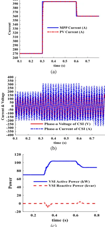
0.75 kW/m2, T is 25 ºC, and the current of the maximum power point is 270 A at the beginning. At t = 0.3 s, the current of the maximum power point is 395 A and it eventually reaches 360 A at t = 0.6 s.
Fig. 11 shows the performance of the CSI-based system under these conditions. Fig. 11(a) illustrates that the DC-side control loop can precisely follow the current reference and exhibit better tracking capability compared with that in the VSI control (Fig. 10(a)). Changing the current through an inductor might cause some problems with the voltage transient. However, in
Iranian Journal of Electrical and Electronic Engineering, Vol. 14, No. 4, December 2018 349
(a) (a)
(b) (b)
(c) (c)
Fig. 10 The VSI-based system performances in response to a step change in the insolation level and ambient temperature: a) The DC-side voltage of the VSI, b) AC-side voltage and current of the VSI and c) Active and reactive power of the VSI.
Fig. 11 The CSI-based system performances in response to a step change in the insolation level and ambient temperature: a) The DC-side current of the CSI, b) AC-side current and voltage of the CSI and c) Active and reactive power of the CSI.
practice irradiation and ambient temperature change slowly, so the output current of the PV generator varies non-severe. Similar to VSI, the CSI works with the unity power factor, as indicated in Fig. 11(b). Furthermore, Fig. 11(c) also illustrates that the PV system delivers the maximum power to the power grid through the CSI and that an exchange of reactive power between the grid and the generator does not occur under normal conditions. The output current of the inverter changes according to the PV generator current and modulation amplitude index, while the output voltage of the inverter changes according to the PV generator power and current.
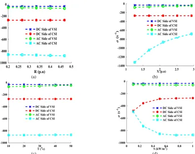
As an applying linearization technique to the state space equations of the system cause to some inaccuracy, to determine the robustness of the proposed control, the patterns of variation of the real parts of the system eigenvalues as functions of different parameters are shown in Fig. 12. For the sake of investigations on the
stability assessment, only real part of the network eigenvalues is considered as shown in Fig. 12. The variations of the imaginary part of the network eigenvalues are considerable, but not as much as the real part of the network eigenvalues.
Fig. 12(a) illustrates the variations in the real part of the dominant eigenvalues as functions of grid resistance
R. The effect of grid resistance variations on system eigenvalues is insignificant. Fig. 12(b) illustrates the variations in the real part of the dominant eigenvalues as functions of grid reactance X. The figure indicates that reactance variations in the grid significantly affect the control of the AC-side of the CSI. The performance of the PV generator is a function of ambient conditions. The ambient temperature and irradiation affect the current, voltage, and resistance of the PV. The effects of ambient temperature on the system eigenvalues are illustrated in Fig. 12(c). At the maximum power point, the effect of ambient is
Iranian Journal of Electrical and Electronic Engineering, Vol. 14, No. 4, December 2018 350
(a) (b)
(c) (d)
Fig. 12 Patterns of variation for the system eigenvalues as functions of the network parameters: a) Variation pattern in the real part of the network eigenvalues as a function of grid resistance, b) Variation pattern in the real part of the network eigenvalues as a function
of grid reactance, c) Variation pattern in the real part of the network eigenvalues as a function of ambient temperature and d) Variation pattern in the real part of the network eigenvalues as a function of irradiation.
noticeable on the voltage. In this case, as temperature increases, the eigenvalue of the AC-side of the VSI control temperature variations on the current is moderate but loops approach the imaginary axis of the
s-plane, whereas a temperature increase does not significantly affect the eigenvalues of the structure of the CSI closed-loop control. Fig. 12(d) illustrates variations in the network eigenvalues as a function of irradiation. Irradiation variations substantially affect the current that corresponds to the maximum power point. The eigenvalues of the DC-side and AC-side of the CSI control structure are highly sensitive to surface variations in solar radiation. Fig. 12(d) illustrates that the eigenvalue of the AC-side control loop, including the CSI, becomes increasingly stable as the irradiation level rises. Meanwhile, the eigenvalue of the DC-side control loop, including the CSI, exhibits the opposite behavior.
The simulation results indicate that specified designs based on the system model can suitably control active and reactive power. So that the proposed simple control structure (without coupling terms) based on phasor variables injects the maximum extractable power of PV system into the grid with unity power factor. The control performance and robustness of both VSI-based and CSI-based systems in the amplitude-phase reference
frame are satisfactory and analogous to the current methods in the d-q reference frame. The closed-loop system with CSI exhibits higher precision and faster response than the closed-loop system with VSI. Furthermore, the VSI-based system is significantly more robust than the CSI-based system against variations under different conditions and disturbances. In addition, the eigenvalues of the AC-side control loops are more sensitive to changes in network conditions and faster than the eigenvalues of the DC-side control loops.
6 Conclusion
This study presents a control strategy for a single-stage three-phase grid-connected PV system based on CSI, as well as a VSI-based system. The synchronous reference frame control is implemented, uses abc to amplitude-phase transformation module. Amplitude or phase of the voltage and the current can be adjusted via only one control variable. The control structure contains two cascaded loops; the outer loop transfers the maximum power based on the output current/voltage control of the PV generator, and the inner loop regulates the CSI/VSI power factor. Maximum power point tracking determines the reference of the CSI/VSI input
Iranian Journal of Electrical and Electronic Engineering, Vol. 14, No. 4, December 2018 351 current/voltage. Power factor is also controlled so that
the inverter voltage and current will be in phase in the AC-side. The simulation results under variations in irradiation levels and ambient temperatures demonstrate appropriate tracking of reference and satisfactory disturbance rejection. The VSI-based system is more robust, whereas the CSI-based system exhibits better control performance.
References
[1] H. Willis and W. Scott, Distributed power generation: planning and evaluation. CRC Press, 2000.
[2] F. Blaabjerg, R. Teodorescu, M. Liserre and A. Timbus, “Overview of control and grid synchronization for distributed power generation systems,” IEEE Transactions on Industrial Electronics, Vol. 53, No. 5, pp. 1398–1409, 2006. [3] J. Carrasco, L. Franquelo, J. Bialasiewicz,
E. Galvan, R. Portillo Guisado, M. Prats, J. Leon and N. Moreno-Alfonso, “Power-electronic systems for the grid integration of renewable energy sources: A survey,” IEEE Transactions on Industrial Electronics, Vol. 53, No. 4, pp. 1002–1016, 2006. [4] Y. Huang, J. Wang, F. Peng and D. W. Yoo,
“Survey of the power conditioning system for PV power generation,” 37th IEEE Power Electronics
Specialists Conference.
[5] B. Sahan, A. Vergara, N. Henze, A. Engler and P. Zacharias, “A single-stage PV module integrated converter based on a low-power current-source inverter,” IEEE Transactions on Industrial Electronics, Vol. 55, No. 7, pp. 2602–2609, 2008. [6] M. Liserre, R. Teodorescu and F. Blaabjerg,
“Stability of photovoltaic and wind turbine grid-connected inverters for a large set of grid impedance values,” IEEE Transactions on Power Electronics, Vol. 21, No. 1, pp. 263–272, 2006.
[7] S. Zheng, P. Wang and L. Ge, “Study on PWM control strategy of photovoltaic grid-connected generation system,” 2006 CES/IEEE 5th International Power Electronics and Motion Control Conference, 2006.
[8] W. Libo, Z. Zhengming and L. Jianzheng, “A single-stage three-phase grid-connected photovoltaic system with modified MPPT method and reactive power compensation,” IEEE Transactions on Energy Conversion, Vol. 22, No. 4, pp. 881–886, 2007.
[9] A. Yazdani and P. Dash, “A control methodology and characterization of dynamics for a photovoltaic (PV) system interfaced with a distribution network,”
IEEE Transactions on Power Delivery, Vol. 24, No. 3, pp. 1538–1551, 2009.
[10] L. Hassaine, E. Olías, J. Quintero and A. Barrado, “Power control for grid connected applications based on the phase shifting of the inverter output voltage with respect to the grid voltage,”
International Journal of Electrical Power & Energy Systems, Vol. 57, pp. 250–260, 2014.
[11] J. Puukko and T. Suntio, “Dynamic properties of a voltage source inverter-based three-phase inverter in photovoltaic application,” IET Renewable Power Generation, Vol. 6, No. 6, pp. 381–391, 2012. [12] A. Yazdani, A. Di Fazio, H. Ghoddami, M. Russo,
M. Kazerani, J. Jatskevich, K. Strunz, S. Leva and J. Martinez, “Modeling guidelines and a benchmark for power system simulation studies of three-phase single-stage photovoltaic systems,” IEEE Transactions on Power Delivery, Vol. 26, No. 2, pp. 1247–1264, 2011.
[13] Y. Neba, “A simple method for suppression of resonance oscillation in PWM current source converter,” IEEE Transactions on Power Electronics, Vol. 20, No. 1, pp. 132–139, 2005. [14] G. Ertasgin, D. Whaley, N. Ertugrul and W. Soong,
“Implementation and performance evaluation of a low-cost current-source grid-connected inverter for PV applications,” 2008 IEEE International Conference on Sustainable Energy Technologies, 2008.
[15] P. Dash and M. Kazerani, “Dynamic modeling and performance analysis of a grid-connected current-source inverter-based photovoltaic system,” IEEE Transactions on Sustainable Energy, Vol. 2, No. 4, pp. 443–450, 2011.
[16] J. Rocabert, A. Luna, F. Blaabjerg and P. Rodríguez, “Control of power converters in AC microgrids,” IEEE Transactions on Power Electronics, Vol. 27, No. 11, pp. 4734–4749, 2012. [17]J. Gow and C. Manning, “Development of a
photovoltaic array model for use in power-electronics simulation studies,” in IEE Proceedings of Electric Power Applications, pp. 193–200, 1999. [18] Y. Wang and B. Ren, “Fault ride-through
enhancement for grid-tied PV systems with robust control,” IEEE Transactions on Industrial Electronics, Vol. 65, No. 3, pp. 2302–2312, 2018.
Iranian Journal of Electrical and Electronic Engineering, Vol. 14, No. 4, December 2018 352 [19] H. Mohomad, S. Saleh and L. Chang, “Disturbance
estimator-based predictive current controller for single-phase interconnected PV systems,” IEEE Transactions on Industry Applications, Vol. 53, No. 5, pp. 4201–4209, 2017.
[20] S. Bal, A. Anurag, M. Nanda and S. Sourav, “Comprehensive analysis and experimental validation of an improved mathematical modeling of photovoltaic array,” Advances in Power Electronics, Vol. 2015, pp. 1–11, 2015.
[21] W. De Soto, S. Klein and W. Beckman, “Improvement and validation of a model for photovoltaic array performance,” Solar Energy, Vol. 80, No. 1, pp. 78–88, 2006.
[22] M. Villalva, J. Gazoli and E. Filho, “Comprehensive approach to modeling and simulation of photovoltaic Arrays,” IEEE Transactions on Power Electronics, Vol. 24, No. 5, pp. 1198–1208, 2009.
[23] K. Bouzidi, M. Chegaar and A. Bouhemadou, “Solar cells parameters evaluation considering the series and shunt resistance,” Solar Energy Materials and Solar Cells, Vol. 91, No. 18, pp. 1647–1651, 2007.
[24] S. K. Chung, “A phase tracking system for three phase utility interface inverters,” IEEE Transactions on Power Electronics, Vol. 15, No. 3, pp. 431–438, 2000.
[25] T. Esram and P. Chapman, “Comparison of photovoltaic array maximum power point tracking techniques,” IEEE Transactions on Energy Conversion, Vol. 22, No. 2, pp. 439–449, 2007
.
[26] H. Rezk and A. Eltamaly, “A comprehensive comparison of different MPPT techniques for photovoltaic systems,” Solar Energy, Vol. 112, pp. 1–11, 2015.
[27] A. Dolara, R. Faranda and S. Leva, “Energy comparison of seven MPPT techniques for PV systems,” Journal of Electromagnetic Analysis and Applications, Vol. 01, No. 03, pp. 152–162, 2009. [28]R. Dorf and R. Bishop, Modern control systems,
13th ed. Pearson, 2017.
M. A. Azghandi received the B.Sc. degree in Electrical Engineering from Islamic Azad University of Gonabad, Gonabad, Iran, in 2009, and the M.Sc. degree in Electrical Engineering from Mazandaran University of Science and Technology, Babol, Iran in 2013. He is currently pursuing the Ph.D. degree in Electrical Engineering with the University of Sistan and Baluchestan, Zahedan, Iran. His research interests include modeling and control of power electronics converters, distributed generation, and microgrids.
S. M. Barakati (S’03–M’08–SM’14) received the B.Sc. and M.Sc., and Ph.D. degrees from Mashhad University, Mashhad, Tabriz University, Tabriz, Iran, and University of Waterloo, Waterloo, Ontario, Canada, in 1993, 1996, and 2008, respectively. He is presently Associate Professor with the Faculty of Electrical and Computer Engineering at the University of Sistan and Baluchestan, Zahedan, Iran. He had Associate Research position in University of Wisconsin-Madison, USA (2008– 2009) and extended visiting Professor positions at the Universities of Ryerson in Toronto and Ecole Polytechnique de Montréal, Canada. His current research interests include power electronic circuits, control systems, renewable energy, FACTS devices, matrix and multilevel converters, and mechatronic systems.
B. Wu (S’89–M’92–SM’99–F’08)
received the Ph.D. degree in Electrical and Computer Engineering from the University of Toronto, Toronto, ON, Canada, in 1993. After being with Rockwell Automation, Cambridge, ON, Canada, as a Senior Engineer, he joined Ryerson University, Toronto, where he is currently a Professor, and the Natural Sciences and Engineering Research Council of Canada (NSERC)/Rockwell Industrial Research Chair in Power Electronics and Electric Drives. He has published more than 280 technical papers, has authored/coauthored two Wiley-IEEE Press books, and holds more than 20 issued/pending patents. Dr. Wu was the recipient of the Gold Medal of the Governor General of Canada, the Premier’s Research Excellence Award, the Ryerson Distinguished Scholar Award, the Ryerson Research Chair Award, and the Natural Sciences and Engineering Research Council of Canada Synergy Award for Innovation. He is a Fellow of the Engineering Institute of Canada and the Canadian Academy of Engineering.
© 2018 by the authors. Licensee IUST, Tehran, Iran. This article is an open access article distributed under the terms and conditions of the Creative Commons Attribution-NonCommercial 4.0 International (CC BY-NC 4.0) license (https://creativecommons.org/licenses/by-nc/4.0/).