Effect of Slits in A Diverging Conical Ring Insert
on Heat Transfer Enhancement in A Cylindrical
Tube
Kinyua Eric Mugambi1, Mathew Kinyanjui2, Murray Humphrey3 1Dep. of Mathematics & Physics, Tech. U. of Mombasa
2Dep. of pure & applied Mathematics, J.K.U.A.T
3Department of statistics & actuarial science, Jomo Kenyatta University of Agriculture and Technology; Kenya.
Abstract: Diverging conical ring insert in a cylindrical tube is a passive augmentation technique aiming to improve the heat transfer enhancement. An insert disrupts the flow creating a mixture between core and near wall fluid leading to enhancement of heat. In this research work hot water is used as the test fluid in a simulation to establish the pressure and temperature variation along a tube 4m long with an insert placed at 3.5m from the entrance. At this position uniform velocity is attained to avoid the boundary layer and pipe entry effect. Analysis of the results shows a positive heat transfer enhancement rate compared with a plain tube, the highest rate achieved when two slits are placed on opposite sides of the conical ring.
Key words: heat transfer enhancement, multi longitudinal vortex, Slit, Diverging ring insert and Thermal performance factor.
I. INTRODUCTION
Heat transfer is a study on exchange of thermal energy through a body or between bodies which occurs when there is a temperature difference. Thermal energy transfers occur from a body with a higher temperature to another with lower temperature. Heat transfer enhancement is an improvement in the performance of a thermal system by change of surface geometry to obtain higher energy efficiency also referred to as heat transfer augmentation. The heat transfer rate can be improved by introducing a disturbance in the fluid flow using different enhancement technologies breaking the viscous and thermal boundary layer. Augmentation techniques are broadly classified into three different categories: Passive, Active and Compound. Passive techniques are those that do not require any direct input of external power, rather they use it from the system itself which ultimately leads to an increase in fluid pressure drop. They are divided into displacement enhancement devices like conical rings and swirl flow devices that produce superimposed swirl flow or secondary recirculation on the axial flow in a tube e.g. helical strip or coiled screw type tube inserts and twisted tapes. Active techniques are those that have external power used to facilitate the desired flow modification and improvement in the rate of heat transfer like in the case of rotating tubes and surface vibration. Compound techniques occur when any two or more of these techniques are employed simultaneously to obtain enhancement in heat transfer that is greater than that produced by either of them when used individually.
II. LITERATURE REVIEW
Ayhan et al. [1]provided the effect of truncated hollow cone inserts on heat transfer and friction in a tube. Durmus [3] investigated
the effect of cutting out conical turbulators on heat transfer with different types of turbulators and different conical-angles of 50, 100,
150 and 200 establishing that heat transfer rate as well as friction coefficients increased with the angles. Promvonge [11] conducted
experiments by inserting several conical rings as turbulators over a test tube with conical rings of three different diameter ratios of the ring to the diameter (d/D = 0.5, 0.6, 0.7) were introduced in the tests and for each ratio the rings were placed with three different arrangements; Converging conical ring-CCR, Diverging conical ring-DCR, Converging diverging conical ring-CDCR in which cold air at ambient air temperature was passed through the tube with the DCR being the most efficient. Fan et al. [4] numerically
investigated turbulent flow and heat transfer in a circular tube fitted with conical strip inserts using k-ε turbulence. Kongkaitpaiboon
different cone angles 30o, 45o and 60o in Reynolds number ranging from 10000 to 34000. They found that the best results in terms of direction of flow are diverging, converging –diverging and converging respectively, while the turbulator best results for the cone
angle are 30o, 45o and 60o respectively. Guo et al. [5] carried out a theoretical study about the effect of a secondary flow on the
laminar convection heat transfer, while Saqr and Wahid [12] proposed an empirical correlation for predicting the entropy augmentation as a function of the swirl number. Nuntadusit et al. [10] studied the effect on Nusselt number of different set ups of multiple swirling jets. As for the design of swirl generators Zohir et al. [13] evaluated the increase of heat transfer rate when modifying the location and pitch angle of the swirl generator upwind the test chamber. Liu et al [8] explained the physical quantity synergy principle from field synergy by reflecting the physical mechanism of convective heat transfer in the laminar and turbulence flows and explained physical essentials on reducing flow resistance by revealing how heat transfer performance is influenced by physical quantity synergy relation on temperature, velocity and pressure. Chen et al. [2] proposed the entransy dissipation based thermal resistance method for heat exchanger performance design and optimization. By setting entransy dissipation as optimization objective and viscous dissipation as a constraint condition, the optimization flow field equation for convective heat transfer is expressed by Meng et al [9]. Therefore the optimum velocity field indicates the basic characteristics of the flow pattern that benefits the heat transfer most for the laminar flow heat transfer in a tube as between 2 to 4 multi-longitudinal vortex pairs.
III. ASSUMPTIONS IN THE STUDY. In this research using a viscous Newtonian fluid, the following assumptions are made:
A. The fluid flow is steady and in the axial direction.
B. The fluid is Newtonian i.e. stress is proportional to the rate of shear force.
C. The no-slip condition is satisfied i.e. on the surface of the solid wall the velocity of the fluid layer adjacent to it is stationary.
D. The fluid is incompressible i.e. density of the fluid is assumed to be a constant.
IV. BOUNDARY CONDITIONS
Using hot water the flow parameters at the inlet of the tube are
u
m
s
z
3
/
while pressure P0 =110,000 Pa andtemperatureT0=370K. The Reynolds number (Re) satisfies the inequality 1000<Re<5000, pressure coefficient: PC =6.5 and Prandtl number: Pr =
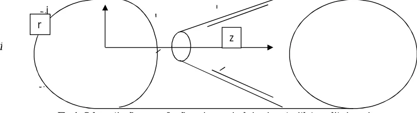
[image:3.612.90.517.464.580.2]1.75, Figure 1 shows the position of a conical ring insert in the cylindrical tube, with the axis indicated. The DCR insert inlet radius is 18mm and the outlet radius is 25mm, with the length along the z axis as 70mm.
Fig 1: Schematic diagram of a diverging conical ring insert with two slits in a pipe.
Momentum flux on the fluid force through the ring at the DCR is
0 2
2
u
rdr
m
a constant and on the wall surfaces
temperature T hot water =T wall.
The conical insert has a half angle of
7.50 in a pipe of radius R= 2.5cm, and a pressure difference of 10k Pa.V. PHYSICAL SIMULATION OF THE FLOW PROBLEM.
To determine the flow parameters we simulate a physical situation by modeling the cylindrical tube with a diverging conical ring insert having slits on the slant edge. A software ‘Solid works’ is used to simulate the flow after construction of the pipe geometry to
j
k
i
r
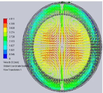
demonstrate a case of hot water flowing in a horizontal pipe. Fluid velocity along the tube is illustrated by a colour code as shown in
figure 2. The slits generate fluid circulation in the tube with axial velocity uz along the axial planes. A cross section diagram at the
[image:4.612.88.528.172.569.2]DCR insert outlet displays the streamlines indicating two multi-longitudinal vortex pairs generated by two slits.
Fig. 2 Streamlines generated by 2 slits form two multi-longitudinal vortex pairs.
The number of vortex pairs is equal to the number of slits on the cone, these causes a mixture of inner core and near wall fluid which enhances heat transfer.
VI. GRAPHICAL REPRESENTATION OF THE RESULTS
A. Variation of Pressure
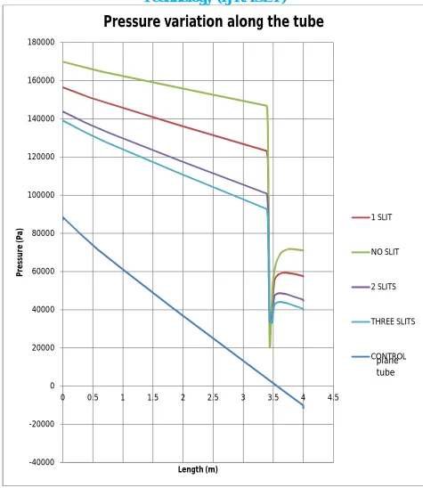
Results are obtained using a 4m long tube of internal radius 0.05m, to compare what happens when there is no conical ring insert and if one is placed in the tube a distance 3.5m from the entrance. Thereafter different DCR inserts are used by having four different
Figure 3: Pressure drop due to an insert placed in a plane tube.
A consistent pressure drop is observed in the four different cases with a DCR insert although a higher-pressure gradient is noted as the number of slits increases.
B. Variation of Temperature along the Tube.
Temperature of the fluid along a tube is determined for the different set ups to compare the effect due to number of slits on heat enhancement.
-40000 -20000 0 20000 40000 60000 80000 100000 120000 140000 160000 180000
0 0.5 1 1.5 2 2.5 3 3.5 4 4.5
P
re
ss
u
re
(
P
a)
Length (m)
Pressure variation along the tube
1 SLIT
NO SLIT
2 SLITS
THREE SLITS
CONTROLplane
Figure 4: Effect of number of slits on heat transfer enhancement.
It is observed that after the pressure drop temperature in the case where DCR insert has two slits attains the highest temperature at the tube’s outlet.
Number of slits on a DCR 0 1 2 3
inlet outlet
T
T
T
0.015356 0.016099 0.016128 0.014882Obtaining the temperature difference between the inlet and outlet we realize that heat gain for the 2 slit on a DCR is greatest among the different set ups.
VII. DETERMINATION OF THERMAL PERFORMANCE FACTOR
The overall heat enhancement factor for a plane tube fitted with a DCR insert is obtained analytically by obtaining several non dimensional factors. If hot water is used as the test fluid then the physical properties can be taken as follows: Inlet temperature
T0=370K, Tube inlet pressure P0 = 110 000 Pa, while the tube outlet pressure is Pout let =101 330Pa =1 atm, maximum velocity v= 4
m/s at the insert inlet, Density of water at 1000c ρ = 957.9kg/m3. Specific heat at constant pressure C
p= 4217kJ/Kg.K, Thermal
conductivity k=0.679W/m.k , coefficient of Dynamic viscosity μ =2.82X10⁻⁴Kg/m.s.
Using the tube’s inner diameter =0.05m and fluid flow velocity = 3.5m/s. Mass flow rate (Kg/s) is the product of density (Kg/m3),
tube’s cross sectional area (m2) and fluid flow velocity then
3
.
5
2
05
.
0
9
.
957
2
Av
m
6.5829 Kg/s at the tubes
inlet. When the fluid encounters the DCR with a smaller radius, a higher pressure drop is experienced and a rise in fluid velocity. Heat transfer rate in a tube bearing a DCR with no slits is
Q=
m
Cp(Tout let –Tin let)=6.5829X 4217(373.0207-373.0054)= 424.7294 J/s. 373 373.005 373.01 373.015 373.02 373.025 373.030 1 2 3 4 5
T e m p e ra tu re (F lu id ) (K) Length (m)
Temperature variation in a 4m long tube.
ONE SLIT
NO SLIT
TWO SLITS
Heat transfer coefficient in a tube bearing DCR insert with no slits is
2748
.
363
,
61
)
0153
.
0
(
4
0360
.
0
7294
.
424
0
DL
T
Q
h
s DCR
.
In a tube bearing a DCR with two slits an approximate increase in inlet area at 2.5x10⁻⁵ m2 per slit, i.e length x width at 0.005m x
0.005m. Then a DCR with two slits as an equivalent inlet diameter of 0.0364m therefore heat transfer rate is
Q=
m
Cp(Tout let –Tin let)=6.5829X 4217X(373.0262-373.0101)=444.1614 J/s.Heat transfer coefficient
DL
T
Q
h
.For the DCR with 2 slits
9943
.
311
,
60
0161
.
0
4
0364
.
0
1614
.
444
2
DL
T
Q
h
s DCR
Thermal performance factor
9828
.
0
2748
.
363
,
61
9943
.
311
,
60
02
s DCR s DCRh
h
In this analysis the wall is non conducting hence flow is adiabatic.
VIII. CONCLUSION
The investigation has been performed to determine heat transfer enhancement rate for varying number of slits on a common DCR insert with a constant pitch ratio.
The simulation of convection heat transfer in a straight circular tube shows that the two multi-longitudinal vortex pair in the tube is a flow pattern that enhances the heat transfer enormously.
IX. ACKNOWLEDGEMENTS
Authors wish to thank the Technical University of Mombasa for the financial support that has made this research work possible and also grateful to Charles Gathua who provided the expertise in the operations of Solid works which greatly assisted in this work.
A. Nomenclature
1) Roman Symbol Quantity
CP Specific heat capacity at constant pressure
D inner diameter of tube, m
d inlet diameter of the diverging conical insert, m
h heat transfer coefficient W/m2k
k thermal conductivity W/mk
L Axial pitch tube length , m
m
mass flow rate , Kg/sNu Nusselt number
P pressure, Pa (Nm-2)
Po pressure at the inlet, Pa (Nm-2)
Pr Prandtl number
Q convential heat transfer
U mean velocity of flow
z
u
axial velocity, m/s2) Greek Symbols Quantity
Small changeHalf angle at the vertex, rad
Coefficient of dynamic viscosity
Fluid density, kg/m3
Thermal performance factor3) List of Abbreviations
DCR Diverging conical ring
REFERENCES
[1] Ayhan, T., Azak,Y., Demirtas, C. and Ayhan, B., (1999) Numerical and experimental investigation of enhancement of turbulent flow heat transfer in tubes by means of truncated hollow cone inserts, Heat Transfer Enhancement of Heat Exchangers, Kluwer Academic Publishers, 347–356
[2] Chen, Q., Liang, X.G. and Guo, Z.Y., (2013) Entransy theory for the optimization of heat transfer. Int Journal of Heat MassTransfer, 63 pp. 65-81. [3] Durmus, A. (2004) Heat transfer and energy loss in cut out conical turbulators. Energy Conversion Management 45, 785-796
[4] Fan, A., Deng, J., Guo, J. and Liu, W., (2011) A numerical study on thermo- hydraulic characteristics of turbulent flow in a circular tube fitted with conical strip inserts. Applications in Thermal Engineering 31, 2819- 2828
[5] Guo, J., Yan, Y., Liu, W., Jiang, F. and Fan, A. (2015) Enhancement of laminar convective heat transfer relying on excitation of transverse secondary swirl flow. Int Journal of Thermal Sciences, vol. 87, pp. 199-206
[6] Karakaya, H. and Durmus, A., (2013) Heat transfer and energy loss in conical spring turbulators, International Journal of Heat and Mass Transfer, Volume 60, pp.756-762
[7] Kongkaitpaiboon, V., Nanan, K. and Eiamsa –ard, S., (2010) Experimental investigation of heat transfer and turbulent flow friction in a tube fitted with perforated conical rings. Int. Communications in Heat and Mass Transfer 37, 560- 567
[8] Liu, W., Liu, Z.C. and Ma, L., (2012) Application of a multi- field synergy principle in the performance evaluation of convective heat transfer enhancement in a tube. China Science Bulletin, 57. pp. 1600- 160
[9] Meng, J.A., Liang, X.G., (2005) Field synergy optimization and enhanced heat transfer by multi-longitudinal vortices flow in tube, Int. Journal of Heat and Mass transfer. 48: 3331- 3337
[10] Nuntadusit, C., Wae-hayee, M., Bunyajitradulya, A. and Eiamsa-ard, S. (2012) Heat transfer enhacement by multiple swirling impinging jets with twisted tape swirl generators, Int. Communications in Heat and Mass Transfer. Vol 39, pp 102 – 10
[11] Promvonge, P. and Eiamsa-ard, S., (2007) Heat transfer behaviors in a tube with combined conical–ring and twisted tape insert, Int. Communication in Heat and Mass Transfer 34: 849-859
[12] Saqr, K.M. and Wahid, M.A., (2014) Effects of swirl intensity on heat transfer and entropy generation in turbulent decaying swirl flow. Applied Thermal Engineering. Vol 70, pp.486- 493.
[13] Zohir, A.E. and Gomaa, A.G. (2013) Heat transfer enhancement through sudden expansion pipe airflow using swirl generator with different angles, Experimental Thermal and Fluid Science. Vol 45, pp. 146 -154.