GA27
·
2827-8
File
~
S380lS31f1S3143001810CUJ8
Syatams
Systems
GA27 -2827-6
File No. 8360/8370/83/4300/8100·09
IBM 3270
Information Display System
3274 Control Unit
Planning, Setup, and
Customizing Guide
Validation Number 06
--..-
~----
-
-
-
-
- .-
~-----
----
-
---_
..
_.-Warning: This equipment generates and uses radio freq-uency energy; if not installed and used properly, i.e., in strict accordance with the instructions manual, it may cause harm-ful interference to radio communications. It has been tested and found to comply with the limits for a Class A computing device persuant to Subpart J of Part 15 of FCC Rules, which are designed to provide reasonable protection against such interference when operated in a commercial environment.
Operation of this equipment in a residential area is likely to cause interference, in which case the user, at his own ex-pense, will be required to take whatever measures may be required to correct the interference.
Seventh Edition (March 1980)
This is a major revision of, and obsoletes, GA27 -2827 -5. It adds planning, setup, and customizing information for the 3274 Model 51C.
This publication is for planning only. Changes are periodically made to the information herein. Before using this publication in connection with the operation of IBM systems or equipment, consult your IBM sales representative or the latest IBM System/360 Bibliography, GC20-0360, or the IBM System/370 Bibliography, GC20-0001, for the editions that are applicable and current.
It is possible that this material may contain reference to, or information about, IBM products (machines and programs), programming, or services that are not announced in your country. Such references or information must not be construed to mean that IBM intends to announce such IBM products, programming, or services in your country.
Publications are not stocked at the address given below; requests for IBM publications should be made to your IBM representative or to the IBM Branch Office serving your locality.
A form for readers' comments is provided at the back of this publication. Address additional comments to IBM Corporation, Department 52Q, Neighborhood Road, Kingston, N. Y. 12401. IBM may use or distribute any of the information you supply in any way it believes appropriate without incurring any obligations whatever. You may, of course, continue to use the information you supply.
Preface
This guide is written for customers, planners, and IBM representatives who may be responsible for:
• Planning the installation and customizing of the IBM 3274 Control Unit Models lA, lB, and lD
• Planning the installation, setup, and customizing of the IBM 3274 Control Unit ModellC and Model5lC
• Planning the installation and setup of the IBM 3278 Display Station, 3279 Color Display Station, 3287 Printer, and 3289 Line Printer
This guide is organized as follows:
Chapter 1, "Planning and Setup," provides planning and setup information for:
IBM 3274 Control Unit
IBM 3278 Display Station
IBM 3279 Color Display Station
IBM 3287 Printer
IBM 3289 Line Printer
Chapter 2, "Introduction to Customizing," describes how and by whom the 3274 customizing procedure is per-formed.
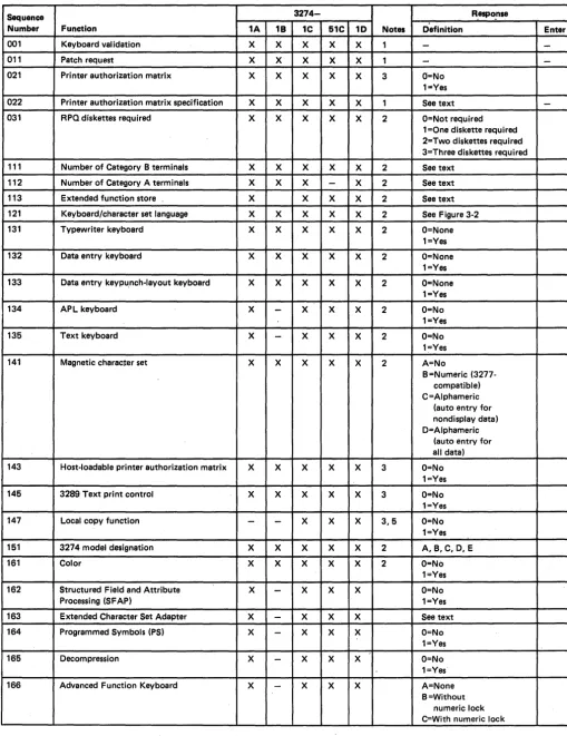
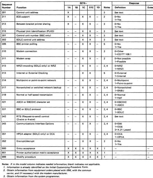
Chapter 3, "Preparing to Customize," describes the sequence numbers used in the 3274 customizing procedure. The sequence numbers are grouped by 3274 model number.
Chapter 4, "Initial Customizing Procedure," describes how to perform the initial customizing of the 3274.
Chapter 5, "Modification Procedure," describes how a 3274 configuration can be modified without performing the entire customizing procedure.
Chapter 6, "Backup :System Diskette Generation Pro-cedure," describes how to generate a backup (duplicate) system diskette.
Chapter 7, "Update-Diskette Installation Procedure," describes how to install an update-diskette in your 3274.
Appendix A, "Planning Checklist," provides a suggested checklist to help you plan your installation.
Appendix B, "3274 Device Cables," provides cable attach-ment information, and also channel attachattach-ment informa-tion for the 3274 Models lA, lB, and ID.
Appendix C describes the use of the Printer Authorization Matrix.
Appendix D is a procedure for verifying the 3274 sub-system after IML is performed.
Appendix E provides a procedure for converging the color patterns on the 3279 Color Display Station during custom-izing.
For detailed information about the functions and features of the above 3270 Information Display System units, see the latest editions of:
An Introduction to the IBM 3270 Information Display System, GA27-2739
IBM 3270 Information Display System: Component Description, GA27-2749
IBM 3270 Information Display System: Installation Manual- PhYSical Planning, GA27-2787
IBM 3270 Information Display System: Configura tor, GA27-2849
IBM 3270 Information Display Station: Character Set Reference, GA27-2837
IBM 3274 Control Unit Operator's Guide, GA23-0023
IBM 3278 Display Station Operator's Guide, GA27-2890
IBM Cryptographic Subsystem Concepts and Facilities, GC22-9063
See Figures P~l through
p-s
for other manuals that may help you plan your installation.An Introduction to the IBM 3270 Information IBM 3270 Information Display SYstem Display System Color and Programmed
-
SymbolsGA27-2739 GA33-3056
IBM 3270 Information IBM 3270 Information Display System Display System Con figura tor Character Set
-
ReferenceGA27-2849 GA27-2837
IBM 3270 Information IBM 3287 Printer Display System Planning and Site Installation Manual- - Preparation Guide Physical Planning
GA27-2787 GA18-2018
-I
I
IBM 3270 Information IBM 3270 Information Installation and Display System Display System Assembly of Coaxial Template (English Units) Template (Metric Units) Cable and Accessories
for Attachment to
IBM Products
GX27-2990 GX27-2999 GA27-2805
Figure pol. General Information and Installation Manuals
IBM 3270 Information IBM 3274 Control Unit Display System Model 1 C Setup IBM 3274 Control Unit Instructions2 Planning, Setup, and GA27-2855
Customizing Guide
1---_
(includes 3278, 3279, IBM 3274 Control UnitModel 51C Setup 3287, and 3289)
Instructions2
GA27-2827
GA23-0047
I
. J
-
-r
T
T
I
IBM 3278 Display Station IBM 3278 Display Station IBM 3278 Display Station
IBM 3278 Display Station Switch Control Unir Setup
with Katakana Feature Japanese English Setup Setup Instructions2 Instructions Setup Instructions I Instructions I
GA27-2838 GA27-2872 GA18-1031 GA 18-1037
I
1
1
J
T
T
-IBM 3279 Color Display IBM 3279 Color Display
Station Switch Control Station Setup Instructions2
Unit Setup Instructions2
GA33-3050
GA33-3066
1
1
T
1
I
IBM 3270 Information
IBM 3276/3278 Display IBM 3279 Color Display Display System
Station Keyboard Station Keyboard Magnetic Accessory
Replacement Instructions Replacement Instructions Setup Instructions
GA27-2873 GA27-2895 GA33-3067
I
I BM Magnetic Hand
IBM 3287 Printer Setup IBM 3289 Line Printer Scanner - Magnetic
Instructions2 (Models 1 Models 1 and 2 Setup Slot Reader Replacement
and 2) Instructions2 Procedures
GA27-3140 G A27-3171
GA24-3663
I Available from I BM Japan only.
2Will be delivered with the indicated machine.
Figure P·2. Customer Setup Manuals
Introduction to Programming the IBM 3270 Information Display System
GC27-6999
IBM 3270 Information Display System Component Description
GA27·2749
IBM 3270 Information Display System Reference Summary
GX20-1878
Figure P-3. Programming Information Manuals
vi
IBM 3270 Information Display System Display Layout Sheet
GX27-2951
IBM 3287 Printer Models 1 and 2 Component Description
GA27·3153
""""'"---IBM 3287 Printer Models 1 C and 2C Component Description
GA27·3229
IBM 3270 Information Display System Character Set Reference
GA27-2837
IBM 3270 Information Display System 3278 Model 5 Layout Sheet
GX27·0014
IBM 3289 Line Printer Component Description
GA27·3176
Forms Design Reference Guide for Printers
IBM 3270 Information Display System Operator's Guide
3275,3277,3284,3286, 3288
GA27-2742
IBM Information Display System Operator's Guide with Katakana Keyboard
3275, 3277, 3284, 3286,3288
GA18-10161
IBM 3270 Information Display System IBM 3274 Control Unit Operator's Guide
GA23-0023
IBM 3270 Information Display System IBM 3276 Control Unit Display Station Operator's Guide
GA18-2040
IBM 3270 Information Display System
IBM 3278 Display Station Operator's Guide
GA27-2890
IBM 3270 Information Display System IBM 3279 Color Display Station Operator's Guide
GA33-3057
1 Available from IBM Japan only,
Figure P-4 (part 1 of 2). Operations Manuals
IBM 3275/3277 Trouble Report Form
GX23-0202
IBM 3284/3286/3288 Trouble Report Form
GX23-0204
IBM 3274 Problem Report Form
GX23-0203
IBM 3276/3278/3279 Problem Report Form
GX23-0201
1
IBM 3270 Information Display System IBM 3276 Control Unit Display Station with Japanese (English) or Katakana Keyboard Operator's Guidel
GA18-2043
A Guide to Using the Test Request Feature on IBM 3270 Information Display System
3271,3272,3275,3277, 3284,3286,3288
GA27-2774
IBM 3276/3278/3279 Problem Report Form Japanese English/Japanese Katakana1
GX18-1033
I
IBM 3270 Information Display Station
IBM 3278 Display Station with Japanese (English) or Katakana Keyboard Operator's Guidel
GA18-1030
ISM 3287 Printer IBM 3287 Printer
Models 1 and 2 Models 1 and 2
Operator's Guide Operator's Trouble Report Form
GA27-3150
GX27-2923
IBM 3289 L.ine Printer IBM 3289 Line Printer IBM 3289 Line Printer
Models 1 and 2 Operator's Models 1 and 2 Operator Models 1 and 2
Guide Reference Summary Operator's Trouble
GA27-3147 GA27-3148 Report Form
GX27-2922
Figure P-4 (Part 2 of 2). Operations Manuals
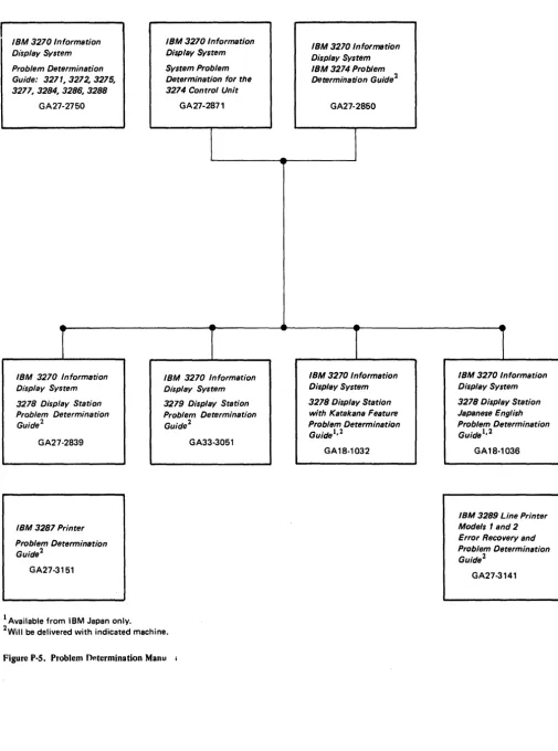
IBM 3270 Information Display System Problem Determination Guide: 3271,3272,3275,
327~3284,328~3288
GA27-2750
IBM 3270 Information Display System 3278 Display Station Problem Determination Guide 2
GA27·2839
IBM 3287 Printer
Problem Determination Guide2
GA27·3151
1 Available from IBM Japan only.
IBM 3270 Information Display System System Problem Determination for the 3274 Control Unit
GA27-2871
IBM 3270 Information Display System 3279 Display Station Problem Determination Guide 2
GA33·3051
[image:10.618.56.561.44.724.2]2WiII be delivered with indicated machine.
Figure P-S. Problem O~termination Manu
IBM 3270 Information Display System IBM 3274 Problem
Determination Guide2
GA27-2850
IBM 3270 Information Display System 3278 Display Station with Katakana Feature Problem Determination GuIde 1, 2
GA18·1032
IBM 3270 Information Display System 3278 Display Station Japanese E ngl ish Problem Determination Guide 1, 2
GA18·1036
IBM 3289 Line Printer
Models 1 and 2
Error Recovery and Problem Determination Guide 2
GA27·3141
Contents
Chapter 1. Planning and Setup 1-1 Introduction 1-1
3274 Cluster Unit Descriptions 1-1 Configuration Planning 1-2 System Planning 1-2
Site Preparation 1-2
Communication Services (3274 Models 1C, 5 Ie) 1-2 Local Channel Attachment (3274 Models lA, IB, and ID) 1-3 Programming Support 1-4
Response Time 1-4 Configuration Support 1-4
Configuration Support A 1-5 Configuration Support B (#9111) 1-5 Configuration Support C (#9112) 1-5
Encrypt/Decrypt Feature (3274 Models lC and SIC) 1-5 Pre-Delivery Planning 1-6
3274 Model lA, 1B, or ID to Local Channel Cables 1-6 3274 Models 1C and SIC Communication Cable 1-6 3274 Models 1C and SIC System Grounding 1-6 3274 Device Cables 1-6
3274 Cluster Network Address Labels 1-7 3274 Customizing 1-7
Subsystem Verification 1-8
Installing Your 3274 Subsystem 1-9 Replacing a 3271 or a 3272 with a 3274 1-9 Problem Determination Procedures 1-10 Relocation/Removal 1-10
Progress Review 1-10
Before Equipment Arrives 1-11 After Equipment Arrives 1-12
IBM Americas/Far East and IBM Europe/Middle East/ Africa 1-17
Supplemental Information 1-17 Safety 1-17
Security 1-17
Personnel Training 1-17 Supplies 1-18
Voice Communication Between 3274 Cluster Operators and Host System Operators 1-18
Reference Manuals 1-18
Chapt~r 2. Introduction to Customizing 2-1 Chapter 3. Preparing to Customize 3-1 3274 ModellA Customizing 3-3
001 Keyboard Validation 3-3 011 Patch Request 3-3
021 Printer Authorization Matrix 3-3
022 Printer Authorization Matrix Specification 3-3 031 RPQ Diskettes Required 3-4
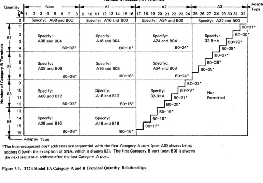
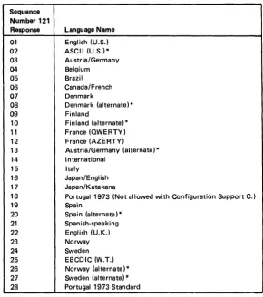
111 Number of Category B Terminals 3-4 112 Number of Category A Terminals 3-5 113 Extended Function Store 3-6 121 Keyboard/Character Set Language 3-6 131 Typewriter Keyboard 3-6
132 Data Entry Keyboard 3-6
133 Data Entry Keypunch Layout Keyboard 3-6 134 APL Keyboard 3-6
135 Text Keyboard 3-6 141 Magnetic Character Set 3-7
143 Host-Loadable Printer Authorization Matrix 3-7 145 3289 Text Print Control 3-8
147 3-8
151 3274 Model Designation 3-8 161 Color 3-8
162 Structured Field and Attribute Processing (SFAP) (Configuration Support COnly) 3-8
163 Extended Character Set Adapter (Configuration Support COnly) 3-8
164 Programmed Symbols (PS) (Configuration Support COnly) 3-8
165 Decompression (Configuration Support COnly) 3-8 166 Advanced Function Keyboard (Configuration
Support COnly) 3-8 201 Control Unit Address 3-8 211 SCS Support 3-8
213 Between Bracket Printer Sharing (SDLC Only) 3-9 215 3-9
301 3-9 302 3-9
305 through 352 Communications Options 3-9 900 Entry Acceptance 3-9
901 Printer Authorization Matrix Acceptance 3-9 999 Modify Procedure 3-9
3274 Models 1B and 1D 3-10 001 Keyboard Validation 3-10 011 Patch Request 3-10
021 Printer Authorization Matrix 3-10
022 Printer Authorization Matrix Specification 3-10 031 RPQ Diskettes Required 3-11
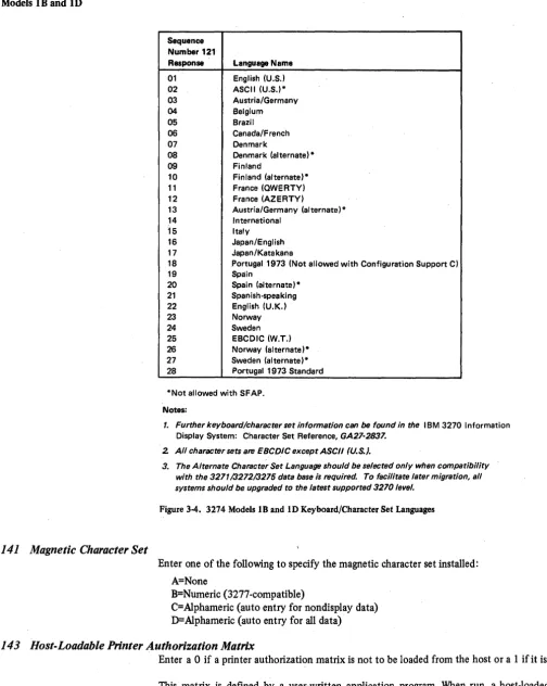
111 Number of Category B Terminals 3-11 112 Number of Category A Terminals 3-12 113 Extended Function Store 3-13 121 Keyboard/Character Set Language 3-13 131 Typewriter Keyboard 3-13
132 Data Entry Keyboard 3-13
133 Data Entry Keypunch Layout Keyboard 3-13 134 APL Keyboard (Modell D Only) 3-13 135 Text Keyboard (ModellD Only) 3-13 141 Magnetic Character Set 3-14
143 Host-Loadable Printer Authorization -Matrix 3-14 145 3289 Text Print Control 3-15
147 Local Copy Function 3-15 151 3274 Model Designation 3-15 161 Color 3-15
162 Structured Field and Attribute Processing (SFAP) (Configuration Support COnly) 3-15 163 Extended Character Set Adapter (Configuration
Support COnly) 3-15
164 Programmed Symbols (PS) (Configuration Support COnly) 3-15
165 Decompression (Configuration Support COnly) 3-15 166 Advanced Function Keyboard (Configuration
Support COnly) 3-15 201 through 352 3-16 900 Entry Acceptance 3-16
901 Printer Authorization Matrix Acceptance 3-16' 999 Modify Procedure 3-16
3274 Models 1C, SIC 3-17
001 Keyboard Validation 3-17 011 Patch Request 3-17
021 Printer Authorization Matrix 3-17
022 Printer Authorization Matrix Specification 3-17 031 RPQ Diskettes Required 3-18
111 Number of Category B Terminals 3-18 112 Number of Category A Terminals (does not
apply to SIC) 3-19
113 Extended Function Store 3-20 121 Keyboard/Character Set Language 3-20
xii
131 Typewriter Keyboard 3-20 132 Data Entry Keyboard 3-20
133 Data Entry Keypunch Layout Keyboard 3-20 134 APL Keyboard 3-21
135 Text Keyboard 3-21 141 Magnetic Character Set 3-22
143 Host-Loadable Printer Authorization Matrix 3-22 145 3289 Text Print Control 3-22
147 Local Copy Function 3-22 151 3274 Model Designation 3-22 161 Color 3-22
162 Structured Field and Attribute Processing (SFAP) (Configuration Support COnly) 3-22 163 Extended Character Set Adapter (Configuration
Support COnly) 3-22
164 Programmed Symbols (PS) (Configuration Support COnly) 3-22
165 Decompression (Configuration Support COnly) 3-23 166 Advanced Function Keyboard (Configuration
Support COnly) 3-23 201 3-23
211 SCS Support (SDLC Only) 3-23
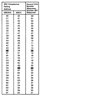
213 Between Bracket Printer Sharing (SDLC Only) 3-23 215 Physical Unit Identification (PUID) (SDLC Only) 3-23 301 Control Unit Number (BSC Only) 3-23
302 SDLC Control Unit Address 3-23 305 BSC Printer Polling (BSC Only) 3-23 310 Modem Connection 3-24
311 Modem Wrap 3-24
313 NRZI (SDLC Only) or NRZ Encoding 3-25 313 (BSC Only) Internal or External Clocking 3-25 314 Multipoint or Point-to-Point Network 3-25 317 Nonswitched- or Switched-Network Backup 3-25 318 Normal or Half-Speed Transmission 3-25 321 EBCDIC or ASCII Character Set 3-26 331 BSC or SDLC Protocol 3-26
342 Request to Send (RTS) Control (2-Wire or 4-Wire) 3-26
343 Communications Interface Options 3-26 351 HPCA (SDLC Only) or CCA Adapter 3-26 352 Encrypt/Decrypt (SDLC Only) 3-26 900 Entry Acceptance 3-26
901 Printer Authorization Matrix Acceptance 3-27 999 Modify Procedure 3-27
Chapter 4. Initial Customizing Procedure 4-1 Initial Customizing Procedure Form 4-3 3274 Diskette Insertion Procedures 4-10 Printer Authorization Matrix Form 4-17
Chapter 5. Modification Procedure 5-1 Modification Procedure Form 5-3 3274 Diskette Insertion Procedures 5-9 Printer Authorization Matrix Form 5-15
Chapter 6. Backup System Diskette Generation Procedure 6-1 Backup System Diskette Form 6-3
3274 Diskette Insertion Procedures 6-8
Chapter 7. Update-Diskette Installation Procedure 7-1 Update-Diskette Installation Procedure for IBM 3274
Control Unit 7-3
Appendix A. Planning Checklist A-I
Appendix B. 3274 Device Cables B-1
Instructions for Completing the 3274 Device Cable Attachment Form B-2
3274 Device Cable Attachment Procedure B-3
3274 Device Cable Attachment Form (Models lA, 1B, lC, and 1D) B-5
3274 Device Cable Attachment Form (Model SIC) B-7 Channel Attachment Information Form (3274 Models lA
and 1D) B-9
Appendix C. Printer Authorization Matrix C-l Description C-l
Defining the Printer Authorization Matrix During Customizing C-4
Printer Authorization Matrix Form C-5
Appendix D. Subsystem Verification Procedure D-l
Appendix E. Color Convergence Procedure E-l
Figures
Figure P-l. Figure P-2. Figure P-3. Figure P-4. Figure P-5. Figure 2-1. Figure 3-1. Figure 3-2. Figure 3-3. Figure 3-4. Figure 3-5. Figure 3-6. Figure 3-7. Figure 4-1. Figure 4-2. Figure 4-3. Figure 4-4. Figure 4-5. Figure 4-6. Figure 4-7. Figure 5-1. Figure 5-2.General Information and Installation Manuals iv Customer Setup Manuals v
Programming Information Manuals vi Operations Manuals vii
Problem Determination Manuals ix Configuration Information Needed 2-3 3274 Model1A Category A and B Terminal Quantity Relationships 3-5
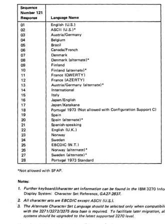
3274 Model1A Keyboard/Character Set Languages 3-7
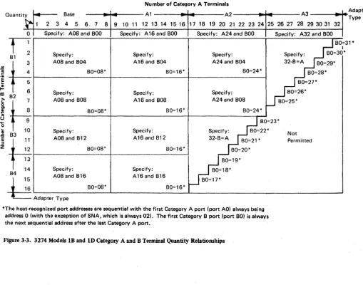
3274 Models 1B and 10 Category A and B Terminal Quantity Relationships 3-12 3274 Models 1B and 10 Keyboard/Character Set Languages 3-14
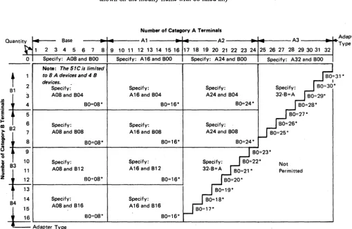
3274 Models 1C and 51C Category A and B Terminal Quantity Relationships 3-19 3274 Models 1C and 51C Keyboard/Character Set Languages 3-21
BSC Polling Address/Control Unit Number Conversion Chart 3-24
Valid Key Positions during Customizing 4-8 Valid Key Positions during Customizing When Using Japanese Katakana and Japanese English Keyboards 4-9
Inserting a Diskette into the 3274 Control Unit 4-10
Operator Codes during Customizing Only 4-12 Steady 8421 Indicator Codes during Customizing Only 4-13
Flashing 8421 Indicator Codes during Customizing Only 4-14
8421 Indicator Codes during IML That Result from an Incorrect Customizing Procedure 4-15 Valid Key Positions during the Modification Procedure 5-7
Valid Key Positions during the Modification Procedure When Using Japanese Katakana and Japanese English Keyboards 5-8
Figure 5-3. Figure 5-4. Figure 5-5. Figure 5-6. Figure 5-7. Figure 6-1. Figure 6-2. Figure 6-3. Figure 6-4. Figure 6-5. Figure 6-6. Figure 6-7. Figure C-1. Figure C-2. Figure C-3. Figure C-4. Figure C-5.
Inserting a Diskette into the 3274 Control Unit 5-9
Operator Codes during the Modification Procedure Only 5-11
Steady 8421 Indicator Codes during the Modification Procedure Only 5-12
Flashing 8421 Indicator Codes during the Modification Procedure Only 5-13
8421 Indicator Codes during IML That Result from an Incorrect Modification Procedure 5-14 Valid Key Positions during Backup System Diskette Generation 6-6
Valid Key Positions dUring Backup System Diskette Generation When Using Japanese Katakana and Japanese English Keyboards 6-7
Inserting a Diskette into the 3274 Control Unit 6-8 Operator Codes During Backup System Diskette Generation Only 6-10
Steady 8421 Indicator Codes during Backup . System Diskette Generation Only 6-11
Flashing 8421 Indicator Codes during Backup System Diskette Generation Only 6-12 8421 Indicator Codes during IML That Result from an Incorrect Backup System Diskette Generation 6-13
Example of a Printer Authorization Matrix C-3 Example of a Completed Printer Authorization Matrix Form C-5
Printer Authorization Matrix Worksheet Example (Models lA, 1B, 1C, and 10) C-6
Sample Printer Authorization Matrix Worksheet (Models lA, 1B, 1C and 10) C-7
Sample Printer Authorization Matrix Worksheet (Model 51C) C-8
Summary of Amendments (March 1980)
to GA27-2827-S by Revision GA27-2827-6
This revision contains the following new material:
• Procedures for setting up and customizing the 3274 Model SIC. This includes updates to general descriptions, sequence numbers, and diagrams for the
SIC. .
• New sequence numbers for:
Structured field and attribute processing (SF AP)
Extended character set adapter
Programmed symbols terminals
Decompression
Advanced function keyboards
• An explanation of Configuration Support C.
• New 8421 codes.
• Chapter 7: Update Diskette Installation Procedure has been rewritten to clarify the procedure.
• Sequence number 343 has been renamed Communica-tion Interface OpCommunica-tion and expanded to allow designaCommunica-tion of the X.21 Leased adapter.
• Sequence number 313 has had a second entry added: Internal or External Clocking for BSC.
• The validation number has been changed to 06 through-out the manual.
xiv
Summary of Amendments (October 29, 1979)
to GA27-2827-4 by Revision GA27-2827-S
This edition contains the follOWing significant changes from the previous edition:
1. An explanation of the various levels of 3274 Configura-tion Support has been added.
2. A recommended sequence for installing a 3274 sub-system has been added .
3. Additional responses have been added to sequence number 113 (Extended Function Store).
4. The following sequence numbers have been added to the customizing process. Each requires a I-digit (0 or 1) response:
161 - Color (Models lA, IB, lC, and 10)
305 - BSC Printer Polling.(ModellC BSC only)
S. Sequence number 215 has been renamed "Physical Unit Identification (PUID)," and its use has been clarified.
6. Appendix 0 has been added to provide verification of the 3274 subsystem after customizing is completed and IML has been performed. The procedure in this appendix should be given to the customizing operator along with the filled-in customizing form.
7. Appendix E provides procedures for converging color patterns on the 3274 during customizing.
Chapter 1. Planning and Setup
In troduc ti on
This planning and setup guide will help you plan the installation of the IBM 3274 Control Unit Models lA, I B, and I D and/or the setup of the following 3270 Information Display System units:
IBM 3274 Control Unit ModellC
IBM 3274 Control Unit Model SIC
IBM 3278 Display Station
IBM 3279 Color Display Station
IBM 3287 Printer
IBM 3289 Line Printer
These units have convenient customer access areas to which your personnel can attach the cluster cables and the keyboard and feature cables.
The 3274 (all models), 3278, 3279, 3287, and 3289 units are delivered with unpacking instructions attached to an outside surface of the shipping carton. In addition to the unpacking instructions, the 3274 Models 1 C and 51 C, 3278, 3273287, and 3289 units have setup instructions inside the shipping carton. The unpacking instructions and the setup instructions are step-by-step procedures that describe the unpacking and setup tasks for the unit. The 3274 must also be customized for the unique cluster configuration.
Chapters 2, 3, and 4 provide the information needed to prepare for, and to customize, all models of the 3274. Included is a suggested form to use when customizing the 3274. Chapter 2 also describes the procedure for installing update diskettes sent to you from time to time by IBM. Chapter 5 provides the information and procedure to modify a system diskette. Chapter 6 provides the information and procedure to generate a backup (duplicate) system diskette. Chapter 7 provides the information needed and the procedures for installing an updated diskette package.
Using the planning information in this guide will help you to ensure that your personnel can (1) unpack, position, set up, customize (3274), and check out the 3274 Models lC and SIC, 3278,3279,3287, and 3289 units, and (2) unpack, position, attach the device cables (coaxial cables that connect the 3274 to the attached units) to, and customize the 3274 Models I A, 1 B, and I D without the help of IBM service representatives (an IBM service representative will install the 3274 Models lA, IB, and ID). As a result, you will be able to use your new display/printer cluster at an early date. If, later, you choose to improve the work flow by relocating these units within the site, your personnel should be able to accomplish the relocation (the help of an IBM service representative is needed to relocate a 3274 Model lA, IB, or ID).
3274 Cluster Unit Descriptions
The 3274 cluster consists of an IBM 3274 Control Unit with attached display stations and/or printers.
For detailed information about the functions and feq.tures of the 3274 and the units that can be attached to the 3274, seethe latest editions of:
An Introduction to the IBM 3270 Information Display System, GA27-2739
IBM 3270 Information Display System: Component Description, GA27-2749
IBM 3270 Information Display System: Character Set Reference, GA27-2837
Configuration Planning
System Planning
Site Preparation
To plan the configuration of the 3274 and the attached units, use the appropriate (U.S., Americas/Far East, or Europe/Middle East/Africa) Configuration Tables in IBM 3270 Information Display System: Configurator, GA27-2849. These tables will help you determine which feature codes are needed to:
• Connect the:
a. 3274 Model lA, lB, or lD to a host system through a local channel.
b. 3274 ModellC or SIC to a host system through communication facilities.
• Provide the required quantity of 3274 terminal adapters.
• Provide feature compatibility among the individual units.
The tables also indicate necessary features, optional features, prerequisite features, and features that cannot coexist.
The following tasks should be planned so that they can be accomplished in a timely manner:
• Site preparation for the 3274 clusters
• Communication facilities preparation for 3274 Models 1 C and 51 C
• Host system channel preparation for 3274 Models 1 A, IB, and lD
• Programming support preparation
• 3274 pre-delivery planning activities
I t may be useful to designate to a person in your organization the responsibility of ensuring that all these tasks are planned. The Planning Checklist in Appendix A of this guide contains the events, in a suggested sequence, that should be planned in order to install a 3274 Model lA, IB, or lD and/or set up a 3274 Model lC or 5IC and the attached units for the first time; it therefore contains more detail than is required for adding to or replacing an existing display/printer system. In either case, each event should be carefully considered so that installing the 3274 Model lA, lB, or lD and/or setting up the 3274 Models 1 C and 51 C and the attached units is problem-free.
The specifications for all physical requirements of the 3274,3278,3279,3287, and 3289 units are given in IBM 3270 Information Display System: Installation Manual - Physical Planning, GA27-2787.
This guide will help you provide compatibility between these units and the following:
• Work space considerations
• Electrical requirements
• Cable requirements and installation
• Power cord plug requirements
• Environmental requirements
Communication Services
(3274 Models lC, 51C)
1-2
Compatibility among these components is a major consideration in new installations. To reduce delays caused by incompatibility, it is recommended that you request assistance from your communications representative and from your IBM representative to determine whether the 3274 Models lC and SIC, modems, communication line, and communicatiounit/adapter are compatible. In addition, schedules should be established to ensure that the modems, communication line, and communication unit/adapter are installed and tested before delivery of Models 1 C and 51 C and the attached units.
Local Channel Attachment (3274 Models lA, IB, and ID)
A plan needs to be established for required changes to your host system selector, multiplexer, or block multiplexer channel configuration; considerations should include device priorities, device data rates, device addresses, I/O interface cable lengths, and changes to the sequence and control (power sequencing and emergency power off) cables.
The Channel Attachment Information Form in Appendix B should be completed before the 3274 is delivered. This information will be required by the IBM service representative at the time of installation. The following information will assist you in completing the form. For further information, see the IBM System/370 Installation Manual - PhYSical Planning, GC22·7004. The 3274 Models, lA, IB, and 10 may be attached to a byte multiplexer, block multiplexer, or selector channel. In most cases the choice of channel attachment depends on system considerations such as channel utilization rather than 3274 operation.
Selector or Block Multiplexer Channel (Non-Byte Mode Operation): If you choose to attach the 3274 Model lA, IB, or lD to a block multiplexer or selector channel, the following options should be selected:
1. Select the 100-Kb data rate (ModellA only).
2. Select burst mode for Model lA. No selection is required for Models IB and 10.
3. Select the priority that will produce the greatest channel efficiency with other attached devices. Factory wiring of high priority is recommended.
The 3274 Models lA, lB, and ID are designed to operate with disconnect command chaining (DCC). Therefore, they will provide greater channel efficiency on a block multiplexer channel than on a selector channel.
Byte Multiplexer Channel (Byte Mode Operation): If you choose to attach the 3274 Model 1 A, 1 B, or 1 D to a byte multiplexer channel, the following considerations and selections should be made:
1. a. Select byte mode for Model 1 A.
b. Select burst mode for Models lB and 10 only if the 3274 is the only device on the channel. In all other cases select byte mode.
2. Select a priority that is below all overrunnable devices on the channel. This can be accomplished by channel cabling between devices and/or the channel priority options.
3. On the Model lA, select the data rate that will produce maximum channel utilization with other devices attached to the same channel. There is no data rate selection option on the Models IB and 10.
When choosing a control unit address for the 3274 Model lA, you may use anyone of the 2S6 possible addresses. The 3274 ModelslB and 10 are very similar to the 3272. The hexadecimal address of the control unit must be a multiple of hex 10 (hex 00, hex 10, hex 20, etc.). If more than 16 devices are attached, the control unit address must be a multiple of hex 20 (hex 00, hex 20, hex 40, etc.).
Programming Support
Response Time
Configuration Support
1-4
The 3274 Models IS and 10 also require an address range. Calculate the number of contiguous addresses as follows:
8 X Number of Type A Terminal Adapters
+
4 X Number of Type B Terminal AdaptersFor example, a control unit address of hex 20 with 2 Type A Terminal Adapters and 3 Type B Terminal Adapters Would be 16
+
12::: 28. Therefore, 28 is the number of contiguous addresses. The 3274 Models IB and 10 will then respond to addresses hex 20 through hex 3B.It is important to plan for proper programming support at the host system. The 3274 clusters can be added to most 3270 display/printer systems with minimal impact on the existing programs. In certain cases, however, host system 'definition (SYSGEN) parameters will have to be changed to accommodate attachment of a 3274 cluster. Infonnation on programming requirements is given in An Introduction to the IBM 3270 Information Display System, GA27-2739, Introduction to Programming the IBM 3270,
GC27-6999, and IBM 3270 Information Display System: Component Description,
GA27·2749.
In addition, it is recommended that for 3274 clusters you enhance your system availability and serviceability by installing the Online Test Executive Program (OLTEP) at the host system. Contact your IBM representative for information about OLTEP.
The response time (performance/throughput) of the devices (displays and printers) attached to a 3274 can be significantly affected by many factors. Some of these factors are:
1. Inbound and outbound message lengths.
2. Frequency and content of message. (tabbing, R/MOTs, selects, etc.)
3. Type of channel and size of CPU.
4. Protocol (SNA or non-SNA; BSC or SOLC).
5. Cluster size, network content, and line speed.
6. Printer speed and type (with or without intelligence, matrix or line printing, LUI, LU2, or LU3 mode, and with or without color option).
7. Screen size and features (PS, color, etc).
8. The associated system control and application programs.
To assist you to determine response time during the early planning stages of your 3274 display/printer subsystem, it is recommended that you contact your IBM sales representa-tive. He has the tools and facilities to evaluate your 3274 subsystem response time.
There are multiple levels of diskettes (Configuration Support levels) available for the 3274 Control Unit. These levels allow selection of the diskettes (feature and system) that will satisfy your requirements.
Configuration Support A
Configuration Support B (#9111)
Configuration Support C (#9112)
This configuration support is shipped with all 3274s unless configuration support B or C is specified. It is the base level of 3274 support including base color on attached terminals,plus support of solicitation of summary maintenance statistics from a 3274 ModellC or 5lC with SNA/SDLC IML.
(Models lA, lC, lD, 5lC only). This support provides support for all 3270 functions included in configuration support A, plus the ability to attach 3278 Display Station Model 5's, and support for the following functions:
• Pacing of inbound message traffic (Models lA, IC/SNA, 5IC/SNA)
• Automatic session recovery in both single and multidomain networks (Modell C/SNA)
• Host notification of changes in the power on/off status at attached terminals (Models IA and lC/SNA, 51C/SNA)
This support provides support for all 3270 functions included in configuration B plus support for the following additional functions: .
• Structured field and attribute processing (SF AP)
• Programmed symbols (PS) on attached terminals
• Extended color on attached terminals
• Extended highlighting
• Decompression of PS load data
• Switched network operation (SNA/SDLC)
• BSC text blocking
• BSC transparency
Encrypt/Decrypt Feature (3274 Models lC and SIC)
It is the customer's responsibility to install a copy of the secondary logical unit (LU) key (the terminal master key) in the 3274 Control Unit Model IC or 51 C equipped with the Encrypt/Decrypt feature (#3680). This should be done by someone in a position of trust, such as a security officer. Once the terminal master key has been installed in the 3274, the 3274 generates a verification pattern based on the terminal master key. A master-key verfication procedure can be performed by any operator without compromising the security of the Encrypt/Decrypt feature. A mercury battery, IBM Part 1743456, is installed in the 3274 to sustain the terminal master key when the 3274 power is off. Replacing this battery, or its equivalent, is also a customer responsibility. Procedures to install and verify the terminal master key, and to replace the mercury battery, are described in IBM 3274 Control Unit Operator's Guide, GA23-0023.
The Encrypt/Decrypt feature should be installed on a new 3274 before the initial customizing is performed. If it is installed on a customized 3274, recustomizing is necessary after installation. ~1he response to sequence number 352 (Encrypt/Decrypt) must be changed to a I . '
Refer also to IBM Cryptographic Subsystem Concepts and Facilities, GA22-9063, for background information, and to IBM 3270 Information Display System: Component Description, GA27-2749, for programming information.
Pre-Delivery Planning
The 3274 Models lA, IB, and ID are installed by an IBM service representative. The 3274 Models IC and SIC, on the other hand, are set up by your personnel. To prevent delays and help ensure a smoother installation/setup, it is recommended that a designated person in your organization:
1. Compile the installation-dependent information described in this section
2. Distribute the installation-dependent information to the appropriate personnel or the IBM service representative
3. Coordinate the activities of your personnel and/or the IBM service representative
3274 Model lA, IB, or ID to Local Channel Cables
The I/O interface and power sequencing cables between a 3274 Model lA, IB, or ID and a local channel will be installed and connected by IBM. However, these cables must be ordered by cable order unless you are replacing a 3272 with a 3274, in which case, the same cables can be used.
3274 Models IC and SIC Communication Cable
The communication cable that connects the 3274 Modell C or 51 C to the modem or channel service unit is delivered with the Models 1 C and 51 C. The standard cable length is 6.1 meters (20 feet); optional cable lengths of 3.0 meters (10 feet), 9.1 meters (30 feet), and 12.2 meters ( 40 feet) may be specified. This cable is connected to the Models 1 C and SIC by the setup personnel. Instructions for connecting the communication cable to the 3274 Models 1 C and 51 C are provided by the 3274 Setup Instructions delivered with these models. Connection to the modem or channel service unit should be discussed with your supplier.
3274 Models 1C and SIC System Grounding
3274 Device Cables
1-6
Frame ground (EIA RS232 or CCITT V.28 pin 1) and signal ground (EIA RS232 or CCITT V.28 pin 7) should be connected together at one point only. This can be either in the 3274 Models IC and SIC or in the modem or channel service unit. It is recommended that, if possible, this connection be made in the modem or channel service unit.
In Europe/Middle East/ Africa countries the majority of modems do not have this connection made. For this reason connection has been made within the 3274 Models IC and SIC at the plant of manufacture.
Note: If you are replacing a 3271 or 3275 with a 3274 Model 1C or 51C, the modem should already have signal ground and frame ground connected together. However, this should be verified with your communications supplier.
Fan-Out Feature: This feature permits two or more control units to be connected to a single modem. If the model has this capability, it is imperative that the signal ground and frame ground wires be connected together in the modem.
Note: If you are replacing a 3271 or a 3272 with a 3274, you can use the existing device cables between the 3271/3272 and the attached units. However, the 3271 or 3272 device cables must be connected/disconnected by an IBM service representative, because the 3271 and 3272 and the attached units do not have customer access areas; It is recommended that, before the IBM service representative. disconnects these cables, you have the cables marked as described below.
To reduce delays associated with connecting these cables to the 3274, it is recommended that each cable be marked at both ends to identify:
• The 3274 connector panel type (Category A panels or Category B panels) and the 3274 port (0 to 31) to which it is to be connected
• The unit type to be attached
For additional information concerning device cables, refer to IBM 3270 Information Display System: Installation Manual - Physical Planning, GA27-2787.
A 3274 Device Cable Attachment form is provided in Appendix B of this guide to help simplify marking and connecting the cables. Instructions for completing all portions of the form except Network Addresses and using the form are also included in Appendix B. A form should be completed for each 3274 cluster you order. Copies of the completed form should be given to the personnel who will install and mark the cables and the personnel who will connect the cables to the 3274. In addition, a copy of the form should be stored in the pocket inside the 3274 customer access door for future reference.
3274 Cluster Network Address Labels
3274 Customizing
Hexadecimal address labels (IBM Part 1743290) are delivered with the 3274. (They will be found, together with a Problem Report Form and Configuration Data card, in the pocket inside the 3274 customer access door.) After each cluster unit is set up, the labels that specify the unit's network address should be attached to the unit's address label holder (if present).
It is recommended that a designated person in your organization (1) obtain the cluster network addresses from the system programmer, (2) enter the addresses in the Network Address column of the 3274 Device Cable Attachment form in Appendix B, and (3) distribute the network addresses information to the person who will attach the address labels.
For information concerning SNA network addresses, refer to Systems Network Architecture General Information: Network Addresses, GA27-3102; for information concerning BSC network addresses, refer to IBM 3270 Information Display System: Component Description, GA27-2749.
Once installation of a 3274 Model lA, 1B, or 10 Control Unit by your IBM service representative (or your own setup of a 3274 Model 1C or SIC) is completed and device cables have been connected, you are ready to configure your system of displays and printers.
The 3274 controls the operations of all the terminals attached to it. Information stored on a diskette (mounted inside the 3274) enables the control unit to perform its terminal control functions. This system diskette, shipped with the 3274, contains microcode to direct control unit functions and performs diagnostic routines to test the 3274 prior to system operation. Before this diskette can perform any useful function in your system, however, you must customize the diskette by writing certain information on it specifically for your configuration. Briefly, customizing is performed by keying in system
Subsystem Verification
1-8
parameters at an attached 3278 or 3279 display station. As a result of this procedure, a unique configuration table is written on the system diskette. In daily operations the operator inserts this customized system diskette in the 3274 and presses the on/off switch to on, or, if this switch is already on, presses the IML button. This action causes the 3274 to execute the diagnostic routines stored on the system diskette. Upon successful completion of these tests, the 3274 is loaded with the configuration data that was stored on the system diskette by the customizing procedure. System operation can now begin.
There are various occasions when it will be necessary to customize your system diskette(s). They are as follows:
• When you initially customize your system diskette (as described above).
• When you wish to duplicate your system diskette. (This new diskette is referred to as a
backup diskette.)
• When you wish to generate a second system diskette to be used for a different purpose. For example, you may choose to have one system diskette to operate in BSC mode and another to operate in SDLC/SNA mode.
• When you need to recustomize your system diskette because you have changed your configuration. This includes adding or removing features such as Encrypt/Decrypt or terminal adapters.
Detailed procedures for performing these tasks are provided in Chapters 2 through 6.
In general, the person who customizes the system diskette uses a
language
diskette and afeature
diskette in conjunction with the customizing procedure. The language diskette is used to customize· the system diskette for languages other than English (U.S.) and Canada/French (both are EBCDIC), and the ASCII (U.S.)1 character set. The feature diskette is used to customize the system diskette for all other cluster parameters. The detailed customizing procedures explain when to insert the required diskettes and direct the person customizing the 3274 to enter the configuration information into the 3274 through a 3278 or 3279 display station attached to port AO of the 3274.To simplify the customizing task, it is recommended that the planner compile the configuration information and supply it to the person responsible for performing the customizing procedure. Included in Chapter 3 are descriptio~s of the parameters to be entered and instructions for completing the Initial Customizing Procedure Form (Chapter 4). A form should be completed for each 3274 ordered prior to delivery of the unit. In addition, configuration information should be copied on the Configuration Data card (shipped with the 3274) and stored in the 3274. (A pocket, located on the inside of the 3274's customer access door, is a convenient place to store this card.)
After customizing is completed, all devices are attached to the 3274, and an initial microcode load (IML) of the subsystem has been performed, it should be verified that the control unit can reach all attached devices. This can be done by performing the Subsystem Verification Procedure (Appendix D). This procedure allows the operator to:
• Verify the number of Type A and B devices configured.
• Determine whether a device is powered on or off.
• Determine whether a device has been disabled as a result of a device error.
This procedure should be provided to the person responsible for performing the customizing procedure.
Installing Your 3274 Subsystem
When installing your 3274 subsystem, you will use various sources of information. When preparing the physical location for your subsystem, you should use the "3274 Device Cable Attachment Form" from Appendix B, the IBM 3270 Injc)rmation Display System:
Installation Manual - PhYSical Planning, GA27 -2787, and the IBM 3287 Printer Site
Planning Guide, GA18-20l8, if your subsystcm includes a 32H7 printer. When your
subsystem arrives and you are ready to install the equipment, you will need some information that is packaged with the various components (unpacking instructions, setup instructions, and problem determination information) and some that will be extracted from this manual (customizing forms and subsystem verification procedure). Some of the forms in this manual require that you fill in information that is unique to your installation. It is recommended that you perform your installation in the following sequence.
Replacing a 3271 or a 3272 with a 3274
When a 3272 is replaced by thl! 3274 Mudd I A, I H, or ID, the existing 3272 local channel attachment and device (coaxial cables between the 3272 and its attached units) cables can be used with the 3274 Model I A, 1 B, or 1 D. However, if the existing 3277/3284/3286/3288 units are to be at tadlcd to the ~274, the device addresses of these units have to be changed. For information cOII~l!rning device addresses for the 3274 cluster, refer to IBM 3270 Information Display System: Component Description,
GA27-2749.
The 250V watertight plug used on the 327'2 is not compatible with the 3274 Model lA, lB, or lD watertight plug. Therefore, when a 3272 is replaced by a 3274 Model lA, lB, or lD, the power receptacle must be changed prior to installation of the 3274. See IBM
3270 Information Display System: Installation Manual - Physical Planning, GA27-2787,
for the type required.
When a 3271 is replaced by a 3274 Model I Cor 51 C, the existing 3271 device cables and modem can be used with the Modd 1 C or 5 I C. Ilowever, t he device addresses of the existing 3277/3284/3286/3288 units and the communication cable that connects the 3271 to its modem cannot be used with the 3274 Model 1 C or 51 C'. A new communication cable is delivered with the 3274 Models I C and 51 C. The standard cable length is 6.1 meters (20 feet)~ optional cable lengths of J.O meters (10 feet), 9.1 meters (30 feet), and 12.2 meters (40 feet) may be spcdtled.
If the existing 3271 or 3272 device cables are to be used with the J174, it is recommended that the cables be marked as described under "3174 Devil;e Cahles."
Notes:
1. The 3277 keyboards and operator ID card /'mJers cannot he used with lite 3278 or
3279.
2. The 3274, when operating in BSC mode, ji.ll1ctiol1s as a 3271 Control Unit, hut is not
compatible with the 3275 Display Station. See IBM 3270 Information Display
System: Component Description, GA27-274Y, jc)r all explanation of lite dljj£'rell('es.
When a 3271 or a 3272 is replaced by a 3274, the following should be considered:
• The 3274 can control up to sixteen 3277s/3284s/3286s/3288s. Therefore, more than one 3274 is required to replace a 3271 or 3272 that has more than 16 of these units attached.
• The 3274 needs a 3278 or 3279 attached to port AO. Therefore, a 3278 or 3279 must be added to the existing units.
Note: All the 3271 or 3272 cluster cables must be connected/disconnected by an IBM service representative, because the 3271 or 3272 and the attached units do not have customer access areas.
Problem Determination Procedures
Relocation/Removal
Progress Review
1 .. 10
The problem determination procedures will help you perform problem determination with minimal reliance on the host system. These procedures use tests contained in the 3274, 3278, 3279, 3287, and 3289 units. See Figure P-5, "Problem Determination Manuals," in the preface.
The procedures enable you to determine whether a problem is being caused by a cluster unit, a system unit or function outside the 3274 cluster, or an operator error. You will also be able to determine whether:
• Operation in a degraded mode is possible.
• Useful work can be done until the problem is corrected.
• The repair action can be scheduled for deferred maintenance.
If you require the help of an IBM service representative, the error message and error condition information should be recorded on a problem report form for the failing unit before the service representative is called. This information will help the service representative resolve the problem as soon as possible.
To ensure proper handling and/or shipping of the 3274 and the attached 3278s/3279s/3287s/3289s when the units are removed or relocated to a different room, building, or mailing address, it is recommended that you call your local IBM branch office. Your IBM representative will supply you with the necessary information and can order the required materials.
Note: The help of an IBM service representative is required to relocate a 3274 Model lA, 1B, or 1D.
To ensure a smooth installation of the 3274 Model lA, 1B, or 10 and/or setup of the 3274 Models 1 C and 51 C and attached units, it is recommended that approximately two months before delivery of the units you 'and the IBM representative review (1) the progress (or the schedule associated with the changes) at the host system site, (2) the communication network and modems, (3) the physical changes needed at the cluster site, and (4) the progress of the pre-delivery planning tasks. At the same time, you and your IBM representative can review the cluster configuration to determine whether the feature mix is adequate.
Before Equipment Arrives
D
Prepare physical location.3274 Control Unit Planning, Setup, and Customizing Guide
GA27-2827
3270 Installation Manual-Physical Planning
GA27-2787
3274 Device Cable Attachment Form
Appendix B
3287 Printer Site Planning and Site Preparation Guide
GA18-20l8
II
Prepare installation-unique information.3274 Control Unit Planning, Setup, and Customizing Guide
GA27-2827
To Physical Installation Personnel
Backup System Diskette Generation Procedure Form
Printer Authorization
Matrix Form Chapter 6
Initial Customizing Procedure Form
Chapter 4
Chapter 4
After Equipment Arrives
Note: Each unit has a Problem Determination Guide packaged with it. If a problem arises while you are setting up a particular component, consult the guide for that component before calling 18M.
II
Unpack and set up display terminals.
3278
or
3279
Unpack Instructions
II
Unpack and set up printers.
3289
l-i2
Unpack Instructions
Unpack I nstructi ons
t
3278 Setup Instructions
GA27·2838
3279 Setup Instructions
GA33·3050
3278
or
3279
Setup Problem Determination Guide
GA27·3151
Lift carton
t
Setup Instructions
GA27·314Q
I
,
II
Unpack and set up
3274Control Unit.
Note: Because special skills and tools are needed to set up Models 1A, 1B, and 1D, ca/l your IBM service representative after your personnel have unpacked and placed the unit Your personnel should continue at step
II
when the IBM service representative completes the setup.3274 Model 1A, 1B, 1C, or 10
3274 Model 51 C
Unpack Instructions
t
Lift carton
CE
Information
Retain for IBM \ Service Representative
\
\
\
\ .
\ \
\
\
\
Setup Instructions
GA27-2855
CE
Information
(Retain for IBM Service Representative)
--
-'---Setup Instructions
GA23-0047
I
II
Connect components
1·14
3274 Control Unit Model 1 A, 1 B, 1 C, or 1 D
3274 Control Unit Model51C
~
~
.""-_.'
__ .":'
,.... .. "'-0·
I .'~ • 0 ,
3278 Display Station or
;3279 Color Di!lplay Station
3287 Pri nter
3~89 Line Printer
3278 Display Station or
3279 Color Display Station
3287 Printer
II
Supply customizing information.
Planning, Setup, and Customizing Guide
GA27-2827
iii
Verify validation numbers.
System Diskette Validation Number
Feature Diskette Validation Number XX
Backup System Diskette Form*
Subsystem Verification Procedure
Printer Authorization Matrix Form*
8421 Indicator Codes
Diskette I nsertion I - - '
Diagram
Keyboard Diagrams
Initial Customizing Procedure Form *
Color Convergence Procedure
* From Step
fJ
-~--~r---
____ _
Must be thesame number
~TO
- T '
CustomizerInitial Customizing Procedure Form
II
Customize the
3274Control Unit.
3274 Control Unit Model 1 A, 1 B, 1 C, or 1 D
3274 Control Unit Model51C
Port AO
Port AO
1m
Press IML button on control panel.
IML button
m
Perform subsystem verification.
1-16
3278 Display Station or 3279 Color Display Station
3278 Display Station or 3279 Color Display Station
IML button
IBM
Americas/Far East and
IBM
Europe/Middle
East/ Africa
Supplemental Information
Safety
Security
Personnel Training
The pre-delivery/setup responsibilities and procedures for the 3274 Models IC and SIC, the 3278, the 3279, the 3287, and the 3289 are the same for U.S. installation and for countries served by IBM A/FE and IBM E/ME/ A.
If you need IBM publications in languages other than English, ask your IBM representative. The IBM representative can provide information concerning the avail-ability of translated IBM publications.
The 3270 units are listed by the Underwriters' Laboratory. Exposed hazardous voltages are not present at the designated customer access areas of the 3274, 3278, 3279, 3287, and 3289 units.
I
DANGERYour personnel should be warned not to go beyond the customer access areas, because there are hazardous voltages within the areas designated for trained personnel only.
Electrical grounding of the 3274 and all the attached units is essential for safety. Be sure that all the facility power receptacles are properly grounded and will accept a grounding type plug (3-prong or equivalent). If you have any questions about the grounding of power receptacles, contact an electrician. For information about power cord plugs, power receptacles, and other safety considerations, refer to IBM 3270 Information Display System: Installation Manual- Physical Planning, GA27-2787.
If the 3274 and the attached units have access to proprietary records or personnel records, it is recommended that you implement appropriate safeguards for the security of the information and the units. IBM makes available some basic functions, but you should decide which ones to use. In addition to safeguards that you may develop, the Security Keylock and Magnetic Reader Control features and the Magnetic Slot Reader accessory may be ordered for 3278s and 3279s. Also available with the 3274 Models IC and SIC is an Encrypt/Decrypt feature that enhances data security in an SNA-communications environment.
If you intend to provide formal training for your operators, you can use the following operator's guides as texts:
• IBM 3274 Control Unit Operator's Guide, GA23-0023
• IBM 3278 Display Station Operator's Guide, GA27·2890
• IBM 3279 Color Display Station Operator's Guide, GA33-30S7-0
• IBM 3287 Printer Operator's Guide, GA27-3ISO
• IBM 3289 Line Printer Models 1 and 2 Operator's Guide, GA27-3I47
The operator's guides describe the basic capabilities of the 3270 units. It is recommended that you use this information to prepare operating procedures for your unique operations. Problem determination guides for the 3274,3278,3279,3287, and 3289 are available to assist operators in determining when an error has been made or when the equipment is not performing properly.
Supplies
The following supplies may be required, depending upon the types of terminals, devices, and features installed.
• Ribbon: Black, IBM Part 1136653 or a customer-selected equivalent, used by the 3287 Models 1 and 2.
• Ribbon: Black, IBM Part 1136634 or a customer-selected equivalent, used by the 3289 Modell.
• Ribbon: Black, IBM Part 1136670 or a customer-selected equivalent, used by the 3289 Model 2.
• Ribbon: Color, IBM Part --- for the 3279 Color Display Station.
• Paper: Single-part continuous or multipart (six-part maximum) for the 3287s and 3289s. See
Forms Design Reference Guide for Printers,
GA24-3488.• Spare magnetic stripe cards.
• Hexadecimal address labels: IBM Part 1743290.
• Mercury Battery: IBM Part 1743456.
Voice Communication between 3274 Cluster
Operators and Host System Operators
Reference Manuals
1-18
It is recommended that a telephone be available at each location to allow the 3274 cluster operators to talk with the host system operators. This will assist the operators in performing the problem determination procedures as well as the daily work.
Chapter 2. Introduction to Customizing
The 3274 Control Unit allows the user 'to specify the configuration under which the 3274 operates. Specification of the 3274 configuration is done using the "customizing procedure." This chapter describes how and by whom the customizing procedure is performed.
Customizing a 3274 Control Unit usually involves a planner and an operator or someone responsible for the actual customizing operation. The planner identifies and compiles the configuration information needed for each 3274 and gives it to the operator, who, following a prompting sequence at a 3278 Display Station or 3279 Color Display Station (with keyboard) attached to the 3274, enters the information. The operator is prompted by a series of sequence numbers that are displayed in the form of three digits; the responses are usually 1-through-5-digit entries. The 3278 or 3279 used for this operation must be attached to port AO of the 3274; it should be near the 3274 during the customizing operation and be clearly identified for the operator. If you are using a 3279, the operator might have to perform a convergence procedure (Appendix E); during'the convergence procedure, error conditions are displayed in the operator information area.
Using Figure 2-1 as a guide, the sequence number descriptions in Chapter 3, and the form supplied in Chapter 4, the planner prepares a list of the responses to be entered. The completed form is given to the operator, who enters each response on the 3278 or 3279 keyboard as each sequence number is displayed. If the entry is acceptable, the display changes to the next sequence number. If the entry is not acceptable, a 1- or 2-digit operator code (Figure 44) is displayed at the top center of the screen to identify the problem. At the end of the series of sequence numbers, the 3278 or 3279 displays all the responses entered to permit verification and correction of the entries.
To prepare for customizing, it is recommended that the planner;
1. Use Chapter 3 as a guide to determine what configuration information is needed for each 3274 model. Figure 2-1 and the sequence number descriptions identify the information sources.
2. Using Figure 2-2 as a guide and the sequence number descriptions in Chapter 3, compile the needed information for each 3274.
Note: The sequence number descriptions contained in Chapter 3 are grouped as follows:
3274 Model lA
3274 Models lB and lD
3274 Models lCand 51C
3. Identify each diskette. A label in the upper right corner of the diskette identifies the diskette type by name, IBM part number, and validation number. The IBM part numbers (listed according to Configuration Support A, B, or C) are;
Feature diskette System diskette Language diskette A 5718400 5718420 5718440 B 5675100 5675101 5718440 C 5675102 5675103 5862415
In addition, you may wish to write some unique designation of your own on the label. For example, you could