--
--
--
--
- - -
- - -
--
===:::;::" -
-- =
-
':'
=
Application Program
1440/1460 Administrative Terminal System
(1440-CX-07X and 1460-CX-OBX)
Programmer's Manual
This system consists of control and functional programs that permit many different
text-processing activities to be carried on simultaneously through different terminals. This reference manual contains a general
description of the programs. It also contains information required by a programmer who wishes to add peripheral programs or new functions ·to the system.
PREFACE
The material in this manual relates to Version 2 of the IBM 1440/1460 Administrative Terminal System program. It obsoletes and replaces the Preliminary Edition issued with Version 1 of the program.
This publication was prepared for production using the IBM 1440/1460 Administrative Terminal System. Page impressions for photo-offset printing were obtained from a typewriter terminal and reduced 15 percent.
£ONTENTS.
INTRODUCTION •••••••••••••••••••••••••••••••••••••••••••••••• 1
GENERAL DESCRIP'rION ••••••••••••••••••••••••••••••••••••••••• 2
PROGRAMMING TECHNIQUES •••••••••••••••••••••••••••••••••••••• 5 Dynamic Storage Allocation •••••••••••••••••••••••••••••••••• 5 Dynamic Core Allocation •••••••••••••••••••••••••••••••••• 5 Dynamic Disk Allocation •••••••••••••••••••••••••••••••••• 7 Dynamic Allocation in ATS •••••••••••••••••••••••••••••••• 8 Multiprogramming •••••••••••••••••••••••••••••••••••••••••••• 8 List Processing ••••••••••••••••••••••••••••••••••••••••••••• 9
THE SYSTEM •••••••••••••••••••••••••••••••••••••••••••••••••• 13 The Multiplexor ••••••••••••••••••••••••••••••••••••••••••••• 13 Status Characters •••••••••••••••••••••••••••••••••••••••• 13 Running Address •••••••••••••••••••••••••••••••••••••••••• 14 Interrupt •••••••••••••••••••••••••••••••••••••••••••••••• 15 Early Warning •••••••••••••••••••••••••••••••••••••••••••• 15
The S c a n . . . 17
The Terluinals ••••••••••••••••••••••••••••••••••••••••••••••• 17 Transmission Code •••••••••••••••••••••••••••••••••••••••• 17 Line Control ••••••••••••••••••••••••••••••••••••••••••••• 17 Output Timing Considerations •••••••••••••••••
0...
17The Disk Files •••••••••••••••••••••••••••••••••••••••••••••• 18 STORAGE ALLOCATION •••••••••••••••••••••••••••••••••••••••••• 21 Disk Storage Allocation ••••••••••••••••••••••••••••••••••••• 21 Core Storage Allocation ••••••••••••••••••••••••••••••••••••• 23 SYSTEM TABLES ••••••••••••••••••••••••••••••••••••••••••••••• 27 System Status Table ••••••••••••••••••••••••••••••••••••••••• 27 Program Status Table •••••••••••••••••••••••••••••••••••••••• 29 Character Status Table •••••••••••••••••••••••••••••••••••••• 30 ,1\rm Table ••••••••••••••••••••••• " . . . 31
'rerminal Status Table ••••••••••••••••••••••••••••••••••••••• 32 Inactive Status •••••••••••••• " . . . 32
Active Status ••••••••••••••••
CI...
32Multiplexor Status Table ••••••••
0...
33List Entries
.0 ... 0...
34Availability Entry •••••••••••
0...
34NJB Entry
.0 ....•... 0...
35ARM Entry • 0 • • • • • • • • • • • • • • • • • • 0 • • • • • • • • • • • • • • • • • • • • • • • • • • • 35 WPA Entry • II • • • • • • • • • • • • • • • • • • II • • • • • • • • • • • • • • • • • • • • • • • • • • • 36 TEXT S'l'REAM PROCESSING . . . 0 • • • .. • • • 37
SYS TEM PROGRAMS •••••••••••••••••••••••••••• ~ •••••••••••••••• Items in Lower Core Storage •••••••••••••••• ~ •••••••••••••••• System Messages •••••••••••••••••••••••••••• ' ••••••••••••••••• The Scheduler •••••••••••••••••••••••••••••• t • • • • • • • • • • • • • • • • Input/Output Control (IOCNX) ••••••••••••••• ~ •••••••••••••••• Chain (CHAIX) ••••••••••••••••••••••••••••••••••••••••••••••• Next Disk Block (NDBKX) •••••••••••••••••••• ~ •••••••••••••••• Purge Disk Block (PDBKX) ••••••••••••••••••• ~ •••••••••••••••• Next Core Block (NCBKX) •••••••••••••••••••• ~ •••••••••••••••• Head of Free Storage (HDFSX) ••••••••••••••• ~ •••••••••••••••• Foot of Free Storage (FTFSX) ••••••••••••••• ~ •••••••••••••••• Set New Job (SNJBX) ••••••••••••••••••••••••••••••••••••••••• Same Uni t (SMUNX) •••••••••••••••••••••••••• It • • • • • • • • • • • • • • • •
New Unit (NWUNX) . . . . Retrieve (RTRVX) . . . (\ ••••••••••••
MISCELLANEOUS PROGRAMMING NOTES ••••••••••••••••••••••••••••• Source Program Preparations ••••••••••••••••••••••••••••••••• Programming Language ••••••••••••••••••••••••••••••••••••• Source Program Decks ••••••••••••••••••••••••••••••••••••• Job Card . . . . Literal Origin (LTORG) Statements •••••••••••••••••••••••• Origin (ORG) Statements •••••••••••••••••••••••••••••••••• COMPOOL (Communication Pool) ••••••••••••••••••••••••••••• Disk Load Program (DSKLD) ••••••••••••••••••••••••••••••••••• Writing Peripheral Programs ••••••••••••••••••••••••••••••••• Writing Application Programs •••••••••••••••••••••••••••••••• Coding Practices ••••••••••••••••••••••••••••••••••••••••• Locating the Attention Line •••••••••••••••••••••••••••••• Interpreting the Attention Line •••••••••••••••••••••••••• Numeric Character Translation •••••••••••••••••••••••••••• Shift Characters ••••••••••••••••••••••••••••••••••••••••• Overlays ••••••••••••••••••••••••••••••••••••••••••••••••• Special Messages ••••••••••••••••••••••••••••••••••••••••• Output Text Streams •••••••••••••••••••••••••••••••••••••• Priority Interrupt •••••••••••••••••••••••••••••••••••••••
SYSTEM OUTPUT FORMATS
...
Permanent Storage Tape •••••••••••••••••••••••••••••••••••••• Card Image Tape ••••••••••••••••••••••••••••••••••••••••••••• Print with Line Numbers Tape •••••••••••••••••••••••••••••••• Upper- and Lowercase Chain Print Tape ••••••••••••••••••••••• Storage Report Tape •••••••••••••••••••••••••••••••••••••••••APPENDIX A: Sample coding for a SRANB subroutine
·
...
APPENDIX B: Sample coding for a RTBLK subroutine·
...
APPENDIX C: Sample coding for a SSPRT subroutine•
••••••••••• APPENDIX D: Sample coding for a routine to read overlays....
APPENDIX E: Sample table for communication between overlays APPENDIX F: Sample coding for a subroutine to chainWorking Storage to another block
•••••••••••••••
....
IN_T;.;.,oR-.O
...
D_U ...
C!.!2~It is intended that this manual serve as a reference manual for
programmers concerned with the Administra'tive Terminal System (ATS).
The manual includes a description of the system, beginning with
ageneral discussion of 'techniques involved and developing into a
detailed treatment of -the programs and indicators. Material is
presented to
pE~rmiteach reader to investigate the subject as his own
interests and requirements demand.
It is assumed that the reader of this manual is familiar with the
following IBM publications:
IBM 1440/1460 Administrative
Termina~System, Terminal Operator's
Manual'(H'-O-Ol8!r
IBM
l14~/t460Administrative
Termina~System, Console Operator's
Manu a
H~227)It is also assumed tha't the reader is familiar with the IBM Systems
Reference Library publications describing the various components of
IBM 1440 and 1460 Data Processing Systems that may be used in connection
with the IBM 1440/1460 Administrative Terminal System.
The reader
GENERAL DESCRIPTION
The IBM 1440/1460 ATS program is concerned with allowing up to 40 remote terminals simultaneous access to a data processing systeim. A wide variety of program-controlled operations are available to each terminal, operating independently.
Keystrokes entered at the terminals are collected by the system as strings of characters called text streams. These text streams are accumulated
in
core storage in 100-character, dynamically allocated data areas called core blocks. Twenty-five characters of the data area are necessary for control, 75 for text. When 75 characters have accumulatedin
a core block, the text is written to IBM 1311 Disk Storage using a chaining technique. Thus, the text stream input from each terminal is in the form of a chain of blocks, each link containing up to 75 characters of text. This chainis
called Working storage. Working Storage for each terminalis
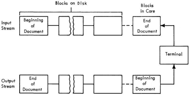
both on the disk and in core storage.Hardware and formatting requirements make the Working Storage (input) text stream unsuitable for transmission back to the terminal. Whenever a printout is requested from the terminal, a ~ of the original
text stream is program-generated. This speci~utput text stream
is
the logical reverse order from the input text stream. Text streams are illustrated in Figure 1.Input Stream
Output Stream
Beginning of Document
End of Document
Blocks on 0 I sk
01_~-
D1_~-Figure 1. Input and output text streams
-Blocks In Core
End of Document
Beginning of Document
~
Terminal
4 "
~
The input text stream is kept intact until deliberately destroyed as a result of a program request from the terminal operator. In contrast, the output text stream
is
destroyed as i tis
used.Documents in Working Storage may be copied into another area of the disk called Permanent Storage. The terminal operator assigns t~he
document a number. This number refers to a specific locat.ion in an index, which, in turn, contains the disk address of the beginning of the document. Permanent Storage
is
chainedin
a manner analogous to Working Storage, in blocks of 900 characters.When accumulating text from the terminals, the system does not
[image:6.613.119.493.336.526.2]a special key called the Attention key.
The Attention key, like all
other keys on the keyboard, generates a unique character that becomes
part of the accumulated text stream.
The terminals and the IBM 1448
Transmission Control Unit (multiplexor), as modified, recognize this
character and cause a computer interrupt after it is received. Any
line containing an Attention character is a request for a program
function.
The characters keyed following the Attention character
indicate which functic)n is requested.
The line cannot be interpreted
until it is completely entered. Thus, no action is taken by the
system until the Carrier Return character is received, signifying the
end of the line. At this time, the line is interpreted, and the
request is processed.
During this period, the terminal keyboard is
locked, and the operator is denied access to the system.
In all
cases, except where the request is supposed to remain for implicit
formatting, the program request line (Attention action) is deleted
from the text stream.
ATS is not a single program but a system of three types of programs:
the control program, application programs, and peripheral programs.
The control program, or Scheduler, schedules the workload for the
application programs, performs all disk input and output, and keeps
the text flowing
betwE~enthe multiplexor and the processor.
The
application programs perform the functions specifically requested by
the terminal operators.
For example, the Format and Print program
generates the output stream when a terminal requests a printout.
Peripheral programs perform unralated background functions such as
tape to printer.
with one exception, all application programs are resident on the disk.
The exc.eption is the End of Unit program (EUNIT), which is described
later in this manual.
When an Attention action is taken by one of
the terminals, the Scheduler reads the appropriate application program
from the disk into a special overlay area.
When the program is
finished with its work, it indicates that fact to the Scheduler, and
the next requested program is read into the same area.
Every application program is assigned a unique three-character entry
in the Program Status Table (PST).
This table contains the location
of every application program, whether disk- or core-resident.
(Disk
addresses are in a compressed form.)
ThE;! programs are numbered by
their r,elative positions in the PST.
This number, called the PST
number, identifies the program.and deterxnines its relative priority.
Thus, when two programs are waiting for the overlay area, the program
with the lower PST number (higher in the PST) is overlaid and executed
first.
The character immediately following the Attention character in an
attention action determines the application program that will process
the request.
Program identification is accomplished by reference to
the Cha.racter Status Table (CST).
This table is composed of 64
entries, one for every possible BCD character. An entry consists of
the PST numbex' of the program that processes the request. When an
Attention action is taken by
o~of the terminals, the character
following the Attention character is located, and the entry in the
CST corresponding to t:.he character is examined.
The entry in the CST
will contain the PST number of the requested program.
The PST is
then examined to locate the program, and the request is processed.
For example, if a terminal requested the next number, the characters:
ATTN n CR
would appear in the text stream. The character following the
Att~ntioncharacter is "n", thus, the entry corresponding to "n" would be
referenced in the CSTo
The entry would contain the PST number of the
Miscellaneous Attention Actions program (MISAC).
The request would
-3-then be sorted into the line or queue of programs waiting for the
overlay area according to the PST number.
t'Jhen the queue was processed
to the point of the entry, the position indicated by the PST number
would be examined
inthe PST, and the physical location of the program
determined.
The program would then be read from the disk and executed.
The CST and PST entries are the communication links to the application
programs.
When a new application program is added, appropriate entries
PROGRAMll1ING TECHNIQUES.
This section contains a general description of some of the programming techniques used in ATS. It must be thoroughly understood before the detailed operation of the system is studied. The ways that these
techniques are used in various parts of the ATS program will be covered in the detailed descriptions of these parts in later sections of this manual.
DYNAMIC STORAGE ALLOCATION
Dynamic Core Allocatio,!!
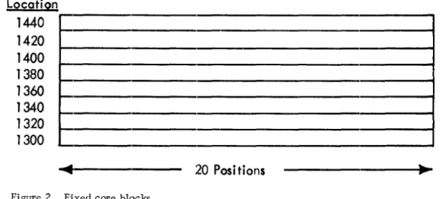
Information is usually stored by means of several contiguous words or blocks having addresses and block lengths -t.hat are known to the
progra~ner. Access to a block is then controlled by the known address modified by an index register. An example is shown in Figure 2.
Location 1440 1420 1400 1380 1360 1340 1320 1300
20 Positions
Figure 2. Fixed core blocks
In a fixed table, block entries are numbered from zero to N-I, where N is the total number of blocks. To reference any block, the block number times the length of the block is loaded into an index register. Reference is then made by addressing the desired field in block zero plus the contents of the index. Thus, in the above example, to
reference the sixth character in the fifth block, 4 (the block number) times 20 (the length of the field) is loaded into an index register. The number 1305 (the character position in block zero) added to the index will yield character position 1385, or the sixth character in the fifth block.
This organization lends itself well to tables of fixed length that change infrequently. However, when dealing with data of unknown length that must be constantly manipulated, a more flexible technique is desired. Dynamic storage allocation is such a technique.
[image:9.617.62.379.347.490.2]Location Pointer Location Pointer
300 400 700 I 800 I
400 500 800 I 900 1
500 600 900 11000
I
600
I
700I
1000 IBlankI
Figure 3, Core blocks chained together with pointers
The address in the block is called a pointer because i t "points" to the next register. A pointer that is blank denotes the end of the table. This technique is also called chaining.
It is immediately apparent that these registers may be randomly located tl.lroughout memory. Thus, contiguous registers are not necessary.
Also, sorting becomes merely the manipulation of addresses, rather than the movement of entire blocks.
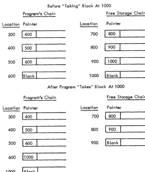
In most systems using dynamic storage, the concept of "free storage" is used. Free storage is a chain of available blocks which are unused at the moment and which may be requested. The technique is de\reloped so that when a program needs an additional block, i t "takes" one from free storage, adds i t to its chain of blocks, and reunites the free storage chain around the missing element. Actually, "taking" a block from free storage entails only the changing of the pointers. The pointer in the last block of the chain associated with the program is changed to point to the block to be extracted from free storage, while the chaining of the free storage blocks is altered to exclude the "missing" block. An example is shown in Figure 4.
Before "Taking" Block At 1000
Program·s Chain Free Storage Chain
Location Pointer Location Pointer
300 1400 I 700 L . . I _80_0--'-_ _ _ _
400 [500 I 800 L - I _90_0--'-_ _ _ _
500 1600 1 900 11000 1
600 IBlank
I
1000 IBlankI
After Program "Takes" Block At 1000
Program·s Chain Free Storage Chain
Location Pointer Location Poi nter
300 1400 700 ' - 1
-80-0~----400 1500 800 .... 1 _90_0--'-_ _ _ _
500 1600 900 1 Blank I
600 11000
I
1000 IBlank 1
[image:10.620.117.356.61.160.2] [image:10.620.119.358.408.692.2]Conversely, when a program has finished with a block, i t is "purged" or "returned" to free storage. Again, the purging of a block entails merely the rechaining of addresses.
Although the examples given above are contiguous, the random nature of this method should be obvious. Also, the program may chain in a block at any point in its Working Storage, not necessarily at the end.
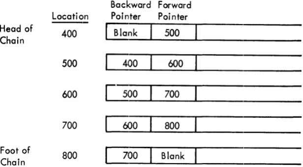
Knowing the address of the first block of a chain enables the program, by following the chaining addresses, to find any particular element in the chain. This search may be facilitated if, in addition to a chaining address pointing to the next block, another address is used to point to the preceding block. Such a scheme is illustrated in Figure 5.
Backward Forward Location Pointer Poi nter Head of
400
~nk
500Chain
500 0 0 0 600 600 L100 700
700
COOo
800Foot of
800 [l00 Blank Chain
Figure 5. Core blocks with two-way chaining
In this scheme, the first address points "backward" in the chain, while the second address points "forward". With this additional address, i t is possible, given any block in the chain, to search in either direction. Note that when the end of the chain is reached going either forward or backward, the chaining address is blank.
Using this met,hod of t:wo-way chaining, i t is desirable to know the locations of both the beginning and the end of the chain, which are called the head and the foot of the chain, respectively. Pointers to these locations are stored in fields with fixed locations termed the "he,ad pointer" and the "foot pointer".
Dynamic Disk Allocatio21
Although the technique described above refers to allocation in core storage, an analogous procedure makes very effective use of random
(disk) storage. When dynamically allocated disk storage is used, the chainin'9 addresses become sector addresses. Here again, two-way chaininlg is desirable to increase the efficiency of a search.
[image:11.613.71.379.234.404.2]portions of the disk that are unused in a contiguous technique. Also, because each cylinder is fully utilized before going to the ne:x:t and because no reshuffling of records is necessary, the number of disk accesses is greatly reduced, especially the disk "seek". Thus, system efficiency is maximized.
~vi th record elements that exceed one sector in length, the dynamic technique can be implemented by chaining groups of sectors. Thus, with long elements, the use of chained groups of sectors (where the groups of sectors are contiguous) results in optimum use of the disk.
A concept analogous to "free storage" is used with dynamic disk
allocation. Instead of a chain of available blocks (sectors), a pool of available sector addresses is kept. These addresses are allocated from one end of the disk (highest addresses, for example) and as more sectors are required, they are added to the pool, moving sequentially across the disk. For example, the pool might begin by including all of the addresses in the highest cylinder of the disk. As these addresses are used up, the addresses in the next cylinder down would be requisitioned.
When a program has finished with a sector, that sector is "purged" or made available for reuse. Again, because a pool of disk addresses, not a chain of free storage, is used, a disk sector is purged by
returning the address to the pool. No additional access to the disk is required.
D~namic Allocation in ATS
Several variations of the above-described allocation techniques are used in the ATS. The one-way chaining technique is used to link the elements in the list area, which is described in the section "List Processing". Two-way chaining is used in several variations in the IOO-character core blocks used to receive text before writing i t to the disk (described in the section "Core Dlocks"). In both the list area and the core blocks, the concept of free storage is used.
Disk storage is allocated by chained sector~ for the text as i t is received and manipulated by the program. A pool of sector addresses is kept as explained above.
In addition to the chained sector storage, called Working Storage, text to be stored permanently is written in chained groups of ten sectors. A similar, but slightly modified, technique of the address pool is used here.
MULTIPROGRAMMING
Multiprogramming is the apparent simultaneous operation of two or more programs. Multiprogramming is not to be confused with
multiprocessing, which is the execution of two or "more programs that are independently and simultaneously executing instructions. An
example of multiprocessing is the simultaneous operation of the Central Processing Unit (CPU) and a data channel in the IBM System/360.
\fuen time is not a prime factor, a program can afford to wait for input/~:>utput operations to be completed.. However, in a real-time situation in which the program must be able to react to external conditions within a specified amount of time, processing time must be conserved.
The "seek" instruction in direct access storage is a very
time-consuming input/output operation. This is so because i t involves the mechanical motion of the access arm. Because seek instruction may be given, and processing may occur at the same time that the arm is in motion, i t does not seriously delay the program. Moreover, an inquiry may be made to see if the arm has reached its destination. If i t has not, more processing may be done.
Multiprogramming is a technique used to take advantage of the processing time while the arm is seeking. In its implementation, two or more
programs are in core at the same time, each with its separate function to perform. When traffic with the disk is required by one of the programs, i t branches to an executive routine conveying the address of the sector(s) that i t needs. The executive routine proceeds to give tile disk seek and then branches to another program in core. The second prograJn works until i t has completed its task or until such time as i t neE~ds access to the disk file. If disk access is required, the second progr~m branches to the executive routine with an appropriate
callin~T sequence giving the address of the sector(s) required. This second request
is
placed in a queue behind the first request.The logic in the Scheduler is that waiting input/output operations that have been completed are processed before any new programs are allowed to operate. Thus, in the above example, after the second program requested a disk access, the Scheduler would first check to see if the input/output of the first program was completed. If so, i t woul.d branch to the first program. If not, i t could branch to a third programtl The actual disk read or write operation is performed wheneve.r control is given to the Scheduler by an interrupt (see the section "The Multiplexor") •
In a multiprogrammed system, from the individual program viewpoint, input/output
is
instantaneous. It requests I/O and, by the time i t execute:s the next ins'truction, the opera'tion is completed. Thus, several programs are all operating, from their individual viewpoints, at the same time.LIST PR.OCESSING
In a multiprogrammed system with a conceivably long queue of waiting input/output requests, some manageable technique must be devised to keep track of the I/O demands. Moreover, if the system is running in real time, i t must react to external conditions arising on a random basis -- conceivably, several arising simultaneously. Thus, demands on the system must also be arranged in a queue.
One solution to these problems is the concept of a list. A list is a group of 'registers, containing control information, placed in a string or queue so thclt they may be processed sequentially.
The control information in a list queuing input/output requests, for example, might include the type of operation (that
is,
read or write) , the area in which the operation is to be made, and the address to branch ,to when the operation is complete.. Such a list is shown inFigure 6.
-9-Operation
1
2 1
3
/
4
/
5
1
Figure 6. Example of an input/output request list
Input/ Output Area
10200
12500
10{JJ0
10500
10400
Branch Address
(JJ56
14561
4480
4480
15975
The first item of each entry is the operation t"l" a read,
"I"
a
write), the second item is the address of the input/output
ar~:!a:and
the third item is the address to which to branch when the operation
is completed.
This kind of list is used for the t'lork in Progress and
Disk Arm queues in the ATS program.
A different set of controls would be needed in a list used to handle
system demands.
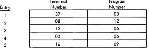
Such a list is shown in Figure 7.
Entry 1 2
3
4
5
Terminal
Number
39
08
12
00
16
Figure 7. Example of a system demand list
Program
Number
03
12
06
06
09
The first item in each entry is the terminal number, and the second
item is an encoded number (PST number) referencing the program that
is to do the work.
The queuing of a list is handled in two ways.
Either it is "first
in, first out" (FIFO), or i t is "last in, first out" (LIFO).
Assuming
that the list entries were processed by always taking the top entry,
a FIFO system would place the latest entry at the bottom of the list,
while a LIFO system would place the latest entry at the top.
In
addition to a basic queuing technique, i t is sometimes desirable to
have some kind of priority implementation.
This can be accomplished
in a FIFO list by sorting the entries so that priority requests are
always pushed to the top.
This kind of list is used for the New Job
queue in the ATS program.
[image:14.613.126.437.56.213.2] [image:14.613.125.434.376.478.2]implemented with the dynamic storage concept. Thus, the list entries can be located at random, connected only by chaining addresses.
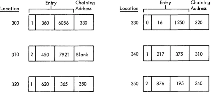
Figure 8 contains an example of a dynamic list.
Entry Chaining Location
r
I I Address Entry" ChainingLocation I I I Address
300~
330GI
16 1250 320340
G
I
217 375 310350
~
I
876I
195 340Figure 8. Example of a dynamic list:
The last item in each entry is a chaining address (pointer). This particular list begins in location 300 and ends in location 310. Note that the blank chaining address denotes the end of the list.
The immediate advantage of a dynamic list is that the addition of new entries and the task of priority sorting become simply the manipulation of chaining addresses, eliminating the necessity of complete record moves. Also, the program required to manipulate a dynamic list is
extremely short.
In a real-time system, there are a number of operations that must be queued. For example, there might be five disk drives attached to the system. If so, i t is apparent that I/O requests can be more efficiently handled if they are queued up for the respective arms where access
is required. In this case, five queues, or one for each arm, would be desirable. In addition, a separate queue of completed I/O requests would be needed. As explained previously, a queue is necessary to process outside demands on the system. The handling of seven separate lists
is
considerably alleviated if the free storaqe conceptis
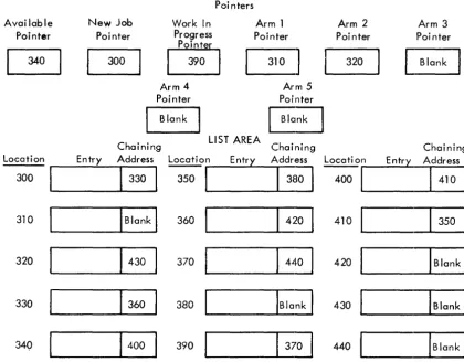
considered. If a chain of Available list entries is used, there is no reas,on why all seven lists cannot be in the same "list area". To implement this condition, eiqht "pointer reqisters" must be allocated in fixed positions. Each of these pointers points to the top entry
in its own dynamic list chain. The Available Pointer, for example, points to the tcp entry in the free storage list. Each of the five Arm Pointers points t() the top entries in its respective list. The Work in Progress Pointer points to the tC)P entry in the completed I/O list and the New Job Pointer points to the top entry in the list of new demands on the system.
In the implementation described above, as in most dynamic storaqe allocation schemes, a pointer that" is blClnk denotes the end of a chain. When a new list entry is needed, say for the New Job list, i t is u:nchained from the Available list and rechained in its proper priority order in the New Job list. Thus, the addition and priority sort of a list entry can be done in one operation. When the entry has served its purpose, i t is purged, or returned, to the Available list.
[image:15.613.70.428.111.276.2]Poi nters
Available New Job Work In Arm 1 Arm 2 Arm 3
Pointer Poi nter Progress Pointer Poi nter Poi nter
[;J
340
0
390G
320L
BlankArm 4 Arm 5
Pointer Pointer
Blank Blank
Chaining LIST AREA Chaining Chaining
Location Entry Address Location Entry Address Locati on Entry Address
1
330 1---1 380
I
1410 1300 350 400
310 IBlank 1 360 420 410
B
320 430 370 440 420 IBlank
I
330 360 380 IBlank 1 430 IBlank 1
340
1
400 390 370 440C B
Figure 9. Example of a dynamic list area
Note the blank Arm Pointers, indicating no entries in their lists.
Note also that the last entry in each chain has a blank pointer.
This is a somewhat simplified example of the List Area in the: ATS
program.
Although this technique may appear complicated from a prograrrmdng
standpoint, it is simple to implement.
Consider the problem of
chaining a list element from the Available list to the bottom of the
New Job list. Only a two- or three-instruction loop is required to
step
~othe bottom of the New Job list. The address in the Available
[image:16.617.131.551.66.394.2]THE SY2!E:!
This section discusses some programming aspects of the systems that use the ATS program. Except where the operation of specially modified equipment is described, the IBM Systems Reference Library publications describing the equipment should also be consulted.
THE MULTIPLEXOR
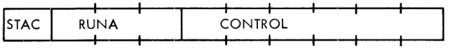
In 1440/1460 ATS, a modified IBM 1448 Transmission Control Unit (multiplexor) is used to buffer text being sent to and received from the terminals. This unit is modified in the sense that many of its functions have been disabled. Communication between the processor and the 1448 is controlled by a table consisting of one ten-character entry for every line attached to the 1448. In the ATS program, this table is called the ~1ultiplexor Status Table (MST). Use of the mul tiplexor i.s point-·to-point. This means that only one terminal is attached to each line, and the polling function is not used. Because of this, the 1448-1440/1460 communication consists of only a status character (S'l'AC) and a running address (RUNA). The status character occupies the first position of the MST entry and is followed by the
three-character running address. The remaining six characters are used for program control and are not referenced by the 1448. They are described in the section "Multiplexor Status Table". An MST entry is organized as ShO~l in Figure 10.
ISTAC
:
:
:
Figure 10. Format of a Multiplexor Status Table (MST) entry
Status Characters
The following status characters may occur in the ATS Multiplexor Status Table:
Receive-Idle (A-bit and l-bit). This status is set ~ the program after an End-of-Block (EOB) character is received from the terminal. It resets the 1448 so that i t will receive characters. It also causes the 1448 to send the Keyboard Unlock character to the terminal.
[image:17.612.77.398.416.453.2]Receive End of Block (A-bit and wordmark).
A special End-of-Block
(EOB) character is transmitted to the 1448 by the terminal immedi,ately
following the Attention or Carrier Return characters.
The EOB character
never reaches core, however.
Instead, the wordmark bit is set in the
status character for that line
~ ~1448.
Receive End of Storage (A-bit and 8-bit). This status is set
~the
1448 whenever it attempts to store characters over a groupmarklwordmark.
-Receive Check (A-bit and 2-bit). If an invalid character is received,
or if the two-character buffer storage overflows, this status is set
~ ~
ll!!.
Transmit (B-bit <;>nly). This status is set
~ ~program to trans:mit
text to the term1nals.
Transmit End of Block (B-bit andwordmark).
This status is set
~the 1448 when it recognizes a record mark in an output area, ind1cating
tfie
~ofthe storage area.
A wordmark is set in the status character
for the appropriate line.
Control (4-bit only). This status can be set
~the program after an
EOB condition to hold the terminal in a stable waiting condition while
it is processing for that line.
The status character appears as follows:
~
Status-Function
B
Transmit
A
Receive
8
End of Storage
4
Control
2
Check
1
Idle
WM
End of Block
Whenever an EOB bit is turned on for any line, the EOB indicator is
also set. Thus, the program can inquire with a branch on indicator
instruction if there is an EOB for any line.
If not, an unnecessary
search through the Multiplexor Status Table for wordmarks can be
avoided.
The processor is allowed to change a status character only afLer ian
EOB character is received.
Any attempt to change a status charac·t:.er
from Receive or Transmit to any other value before an EOB characber
is received will halt the system.
The processor is permitted to
iSe~the status character to Control after an EOB is detected.
It is then
permissible for the processor to later change Control to either
Receive-Idle or Transmit.
Running Address
The processor sets the running address to the core address where the
1448 is to deposit characters received or get characters for
address each time it deposits or transmits a character.
Between
scans, the running address will always point to one character beyond
where t:he last operation occurred.
Although the running address will
not
stE~Ppast a groupmark/wordmark when receiving text, a character
will nE!Ver be stored in place of a groupmark/wordmark.
Whenever a
charact~er
might be stored in place of a groupmark/wordmark in the
ReceivE! status, the End-of-Storage bit is set in the status character
and all subsequent characters received are lost. This loss can be
prevented if the Early Warning feature (see below) is used.
Encoun1:.ering a groupmark (with or without wordmark) in the Transmit
status will cause the system to Check Reset.
The running address, unlike the status character, may be reset at any
time by the Scheduler or by an application program.
A word of caution
is
neCE!SSary here.
The 1448 Transmission Control unit will not step
the running address a.cross a 4000-character boundary.
Since such a
boundary occurs in the half-track area (the 8K boundary, see the
section "Core Allocation"), this fact should be well noted.
Inter~
The 1448 will set a request interrupt condition in the processor
whenever it receives the EOB character from any terminal.
An interrupt
is also requested when the 1448 buffers are full in Receive status,
or empt.y in T:ransmi t status. An interrupt cannot occur when a program
is executing'instructions that are less than five characters in length.
The rationale for this is that the program might be chaining, and an
interrupt would surely bring disaster. When an instruction greater
than four characters is read into the A* and B* registers, the
instruction counter is immediately changed, effecting a branch to
position 181 (182 in some systems).
The processing of an interrupt is done by the Scheduler.
Other
programmers need not be concerned about the interrupt as their program
will be compl,etely unaware of it. Contr:ol is returned to the
inter~lpted
instruction with index registers, overflow indicator, and
high-lc)w-equal indicators restored.
It is possible to disable and enable the interrupts. All of the
system subroutines (available for use by any program) disable the
interrupts to prevent entries from more than one program at the same
time.
Interrupts are enabled when contx"ol is returned to the program
calling them.
When changing the status character for a terminal, it
is
imperative that application programs set the running address before
the st,atus character
ischanged.
Early Trlarninq
One of the most important features of the 1448 Transmission Control
Unit is the Early Warning Indicator.
If a character being received
from the terminal is stored in place of a groupmark (without a
wordmark), the Early Warning Indicator goes on.
In the ATS program,
charac'ters are received and transmitted from lOO-character, dynamically
alloca'ted core blocks.
When receiving from the terminal, the block
is
allowed to fill up, and then it is written to the 1311 Disk Storage.
The Early Warning Indicator eliminates the wait that a terminal would
experience when a new block is assignede
When the Early Warning
Indicator goes on after a 1448 scan, the Scheduler locates the terminal
requiring service, starts the characters flowing into a new block and
-15-IBM 1440/1460 Administrative Terminal System Terminal Code Translation
Terminal To Processor Processor To Terminal
Keyed 1 2 3 4 5 6 7 8 9 o A B C D E F G H I J K L M N
o
P Q R S T U V W X Y Z/
IReceived T ransm i tted
1 2 3 8 4 6 5 7 9 P
,
X V U C A Zo
+ W Y J S Q D F N R @ T L $/
I o K G E M H BTERMI NAL SHIFT CHARACTERS (Where Different)
Downshift 1 2 3 4 5 6 7 8 9 o
/
Upshift :f: @ # $ % ¢ & * ? FUNCTIONAL CODESName Graphic Bits
Upshift GR (001110) Downshift LS (111110) Tab *L (111101) Return *R (101101) Attention WS (011101) Backspace
.
,
(101110) Space (000000) Dummy ( (011100)Program-Generated Codes
* Record Mark RM (0110 10) ** Groupmark GM (111111)
* A RM in the input stream indicates a stop code; in the output stream it stops transmission to the 1448.
** A GM in the input stream indicates the end of val id text in that block.
Note: In ATS text stream there is a wordmark over the initial downshift of each unit and over every Carrier Return entered in the automatic mode.
1 2 3 4 5 6 7 8 9 o A B C D E F G H I J K L M N
o
P Q R S T U V W X Y Z,
+ @/
$Figure 11. Translation table for ATS terminal transmissions
[image:20.618.160.471.46.698.2]queues the old block in the appropriate Arm list, to be written to
disk storage.
The SC'll!,
The 1448 scan instruction is given by the Scheduler.
When this
instruction is ,executed, the 1448 empties its buffers if receiving
text, fetches two characters if transmitting, sets the status character
for eac:h term.inal, and turns the EOB and Early Warning Indicators on
if appropriate. The Scheduler must then react to any EOB or Early
Warning Indicator
set~by the 1448.
THE TERMINALS
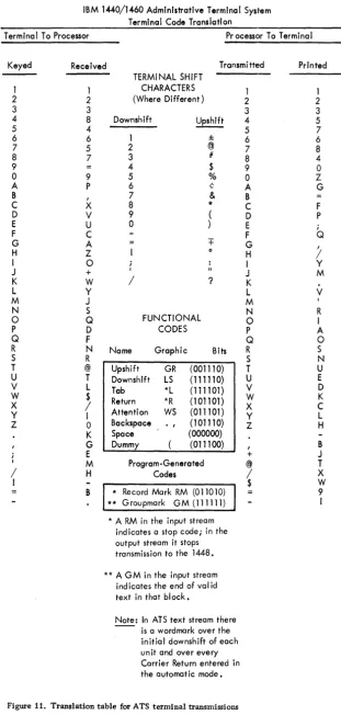
Transmission Code
Terminals for the 1440/1460 ATS have a typewriter mechanism similar
to that of the IBM SELECTRIC
t.ft)typewriter. The 6-bit codes generated
by depressing the various let1:er and function keys (Shifts, Tabs,
Backspaces, and Carrier Returns) on the terminal keyboard do not
correspond to the 6-bit BCD codes normally used in IBM 1440/1460 Data
Processing Systems.
This means that ATS programs that are concerned
with the content of the text stream generated by the terminal must
identify these codes.
Also, when data is transmitted to standard
input/output units, i t must be translated to standard BCD codes to
get satisfactory results. However, all text stream data is stored
within ATS in the terminal code.
A two-way translation table is given
in Figure 11.
Line Control
Line control codes used to convey control information between the
multiplexor and the terminals are generated and removed automatically
by the system.
When the Attention or Carrier Return keys are depressed
the apl)ropria'te character codes are transmi tted, followed by line
codes in character time.
The terminal keyboard is locked.
The
terminal keyboard will remain locked until the multiplexor is set to
Receive-Idle status for the terminal. This causes a Restore character
to be transmi,tted to the terminal (by the 1448), which unlocks the
termincll keyboard.
Output Timing Considerations
Since
1~hefixed time-out feature of the 1448 is not used in ATS, there
is no interlock when functional control characters are transmitted
to the terminals.
Because of this, text sent immediately behind a
Tab,
IJld~x,.orCarrier Return character will print while the SELECTRIC
is in motion.
To avoid this problem, a series of dununy
characters (Upshifts or Downshifts, as appropriate) are put
~ntothe
The number of these dummy characters is calculated so that the print element comes to rest just before the next printing character is transmitted. The Attention character (word separator) will inde~( the platen if transmitted to the terminal. An Index character (Attention character) requires one dummy character. The formula for computing the number of dummy characters required for Tabs and Carrier Returns is the number 0 f character positions to travel divided by ten, p:Lus
two, thus:
Number of Dummy Characters
=
Number of Character Positions + 216
THE DISK FILES
Disk operations inATS are performed by the Scheduler and an I/O control program (IOCNX) with the help of a subroutine (SEEKS). These operations are made by requesting the system to perform them and are never attempted by application programs directly.
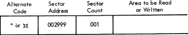
To obtain disk input/output, an application program must first set up the disk corttrol field. This is a ten-character field immediately preceding the area where the operation takes place. The first character of the field is an asterisk (a right parenthesis or lozenge for 1301 addresses), as the alternate code feature is not used in the system. The next six positions are occupied by the sector address. This address is the actual address of the sector to be read or written. The next three positions are the sector count or the number of
contiguous sectors that are to be read or written, beginning with the sector in the sector address portion of the field. A disk control field is shown in Figure 12.
Alternate Code
*
or ):(
Sector Address
00'1999
Sector Count
001
Figure 12. Example of a disk control field
Area to be Read or Written
An IBM 1316 Disk Pack used on the IBM 1311 Disk Storage Drive has ten
r~cording surfaces. Each recording surface is composed of 100 concentric rings or tracks. These tracks are divided into 20
addressable sectors of ~O characters each (all disk operations in the system are in the Load Mode). There are ten access heads, vertically aligned, that move in unison on an arm. These heads read or write information on the tracks. Since the concentric tracks are also aligned vertically, when the arm is in position on any track, all of the tracks in vertical alignment (a "cylinder") are available. The 1311 can theoretically handle up to 200 contiguous sectors in a cylinder with one disk operation. Although the 1311 will switch automatically from track to track within a cylinder, i t is important to note that automatic switching from cylinder to cylinder is
[image:22.613.110.420.444.502.2]Starting from the bottom of the outermost cylinder, the sectors are
addressed beginning with 0 and ending wi.th 199 at the top of the
cylind4er.
The second cylinder is addressed from 200 to 399, and so
on.
Thus, the low address in each cylinder is addressed as an even
mUltiple of 200.
The addresses in a multiple drive system continue in sequence from
drive "to drive.
Thus, the highest sector address on drive 0 is 19999,
and drive 1 commences with address 20000.
The programmer need only
be concerned with the address, however, as the hardware knows which
drive to reference by any sector address.
A g;roupmark/wordmark in the area receivi.ng or writing the information
ends the operation.
This groupmark/wordmark should coincide exa.ctly
with the end of the area as established by the sector count.
In ATS,
this is taken care of automatically by the Scheduler.
However,
application p,rograms should never have groupmark/wordmarks within the
area where the operation is to take place or else an error condition
known as "wro:ng length record" will occur.
In ATS " all possible disk errors are checked.
These errors are:
wrong length record, address compare, access inoperable, and parity.
If any error should arise, seven additional attempts are made to
perform the operation.
If it is still unsuccessful, the Scheduler
CYLINDER
o
o
[FBK AREA 2001
I
ATTEN230
I
MISAC100 199
FRPRT
320 399
COINS
2 [00 480
i
OO
51
0 599799
3 PERMANENT STORAGE BIT MAP 800 840 870 900
ISKNTP
I
DELET940 960 999 920
4
I
SECRDI
SPRNT IREDTP IWRTTP , RPOR'ii 1000 1090 1120 1140 1160 1175 1l9i5
I
KLCUTI
CRDSLI
PERPTI
ARCRT MPLppiAvai1ab1el 13996 Available
7
r
400
Available
1500 1550 1580 1599
, ATSDD , ATSTR
I
SSDDl
8
1670 ,1685 1700
I
DSKDM DSKMN [SCHED1899
9 CORED-ATSDD WORK AREA
2000 2199
10 PERMANENT STORAGE INDEX
11 PERMANENT STORAGE INDEX
2500 2599
12 PERMANENT STORAGE INDEX 5-DIGIT INDEX EXTENSION 13 (1311 Permanent Storage may begin at 2500)
6800
34 END OF 5-DIGIT INDEX EXTENSION Variable
variable ... 1 _----'1=3~1;;;..;;1;;...;...P....;;;.E=R=MAN==E.;;..;.N..;;;;.T_S;;;..T;;;..O;;;;..;RA~G=E~_ ...
! ___
W.;.;.O.;;;...RK;....;;;..;.;I=N~G;;;...,.;;;S;;..;;T;;..;;O=R=A;;..;;G=E _____ ,IVariablel HIGHEST WORKING STORAGE CYLINDER ] up to 499
[image:24.612.135.548.64.574.2]STORAGl~
ALLOCATION
DISK
S~rORAGEALLOCATION
In ATS, all disk operations are performed in the sector format and
the LOcld Mode (with wordmarks).
A disk pack has
20sectors per track
and
10tracks per cylinder, or
200sectors per cylinder.
Since there
are
100cylinders per pack, there are
20,000sectors per pack to be
allocated. The minimum configuration for ATS is one disk drive (two
are recommended), yielding a minimum capacity of
20,000sectors. The
first
:~ocylinders or
4,000sectors are allocated to programs and
control information. All other sectors are used for storing text.
Figure
13contains a layout of disk storage.
Significant disk areas ares
Ij,
Firs't Block Area (sectors 0 through 39). The first
40sectors
are allocated-to contror-information, one sector for each terminal.
These sectors hold the tab stop settings, control information for
correc1:ions and insertions, control information for text formatting,
and the pointer to the first block (disk) in a terminal chain. This
pointel: is te:rmed the ANXB (Address of the Next Block), and it occupies
the last five positions of each block. Here again, a pointer that
is
blal~indicates that there are no sectors chained for a terminal.
20 ~tional
:£erminal
~(sectors
40through
79).341
Peripheral Eevice Control (sectors
80through 99).
441
AfPlication Programs (sectors
100through
599and
800through
1119).
Tfil.s clrea contal.ns the main system application programs.
Anappliccltion program consists of a basic routine plus overlays if
needed
41The basic routine is
20sectors long, while an overlay is
10
sect:ors. As many overlays as are necessary may be appended to an
application program.
5.
Bit
~fP(sectors
600through
799).The bit map is a map of
all of
the1na~-tracks allocated for permanent storage and indicates
which half-tracks are available.
6.
Scheduler, s,stem Subroutines,
EUNIT and HSKPG (sectors
1700 thro~MnT.
- hl.s lOO-sector sectl.on l.s-re'ad l.nto core in one
operation by the bootstrap routine to initialize or restart the system.
Sectors
1794through
1799of this section contain the ATS COMPOOL
(see the section "COMPOOL").
7.
Permanent Storage Index (sectors
2000through
2500if
four-digit document numbers are used, or
2000through
6999if the
five-digit document number option is used).
The Permanent Storage Index
holds the pointers for each dynamically allocated chain of Permclnent
Storage.
Each entry in the index is associated with a number assigned
to a document by a terminal. These numbers are between
1and 9999,
for thEI four-,ligit option or between
1and
99999for the five-digit
option.. The sector corresponding to document zero is used to contain
the poj.nter for the next half-track available (NHTA).
8.
Peripheral Overlay
LibrClr~and User-Written Application
Programs ( sectors
1120
through
159 )
:-i?,arts of €fil.s area may be used
by perl.pheral programs that may be supplied with future versions of
the system.
Modifica'tion of the locations of programs stored in this
area is
discu~)sedin 'the section "Writing Peripheral Programs".
-21-Location
0 Card Unit and Printer Buffers
333
Scheduler System Subrouti nes
System Messages EUNIT 5900
Overlay Area (Application Programs) 7700
Ha I f-Track Area 8600
System Tables 9600
List Area 10000
Dynamically Allocated
100-Character Core Blocks
Variable
Peripheral Overlay Area 16000
[image:26.615.159.507.53.533.2]9
41Permanent StoraAe (both upper and lower bounds are determined
by the user).
If
an
IB
1301 Disk Storage is installed, all Permanent
Storage is on the 1301.
Permanent Storage consists of dynamically
chained groups of ten contiguous sectors (half-tracks). Messages
transmitted between terminals are handled similar to Permanent Storage
and also occupy this area.
10. Working Storage (from address determined by user downward) •
Working Storage consIsts of single sectors dynamically allocated as
explained
inthe section "Dynamic Disk Location".
CORE STORAGE ALLOCATION
The core storage requirements for l440/l460 ATS are 16,000 positions.
A clearer understanding of the organization of the system can be
gained by understanding the physical allocation of core storage, which
is
shown in Figure 14.
Core storage may be divided into eight areas:
1..
Card Buffers, 0 through 332.
This area
isused for peripheral
and main system card ·operations.
2"
Main System Programs and EUNIT, 333 through 5899.
The
Scheduler~the
major program-rn the system.
Its function
isto
control the flow of text to and from the terminals, give the reads
or writes queued up for the disk file, and schedule work among the
various functional (application) programs.
In addition to the Scheduler, the input/output control program (IOCNX)
is also in this area.
IOCNX is responsible for queuing input/output
requests. Al:so in this area are the system subroutines that may be
used by application programs.
Among the more important subroutines
are the following:
Set New Job (SNJBX) is responsible for the queue of new jobs for
application programs.
Nt~w
Core Block (NCBKX), Head of Free Storage (HDFSX), and Foot
of Free Storage (FTFSX) are responsible for the maintenance of
the free storage chain of 100-character core blocks.
Nf~xt
Disk Block (NDBKX) and Purge Disk Block (PDBKX) are
responsible for the pool of availablle disk sector addresses
used for Working Storage.
Also
inthis area,
inaddition to the main system programs,
isa small
appliccltion p:rogram called End of Unit (EUNIT), which deletes
nonprinting characters preceding the Carrier Return Character at the
end of a unit.
EUNIT is the only application program that is resident
in corE3 while the system is operating.
3..
Overla¥ Area (application programs), 5900 through 7699.
All
of the app11cat1on-programs, with the exception of EUNIT described
above, are re.sident on the disk file. These programs process specific
requests from the terminals. When a request is made, SNJBX places a
program request in the New Job queue, and when convenient for the
system, the appropriate program is read into the Overlay Area and
given (:ontrol.
The application programs
inthe system are:
A1:tentio:n (ATTEN) handles the erasing and deleting functions in
the system. ATTEN also serves as a preprocessor to other
-23-application programs and processes system errors or transmission errors.
Bulk Move and Erase (BUKOP) processes the moving and deletion of text in Working Storage.
Correct;ons and Insertions (COINS) processes the calling out of lines and units for correction, and the insertion of lines or units into previously keyed text.
Card to SELECTRIC (CRDSL) creates documents in ATS format from card or unblocked tape input.
Delete (DELET) updates the bit map to indicate available half-tracks released by deleted documents.
Files Preprocessor (FILEP) does the initial processing of requests pertaining to Permanent Storage: Store, Get, Delete, Transmit, Message, and Permanent Storage Tape.
Format and Print (FRPRT) generates a formatted text stream for transmission to the terminals.
Get Document (GETDC) retrieves documents from Permanent Storage.
Housekeeping (HSKPG) is the exception that does not respond to requests f~om the terminals. It prepares core storage and
initializes the cycling of the system when the system is loaded. It also restarts the system in a system failure situation.
Unlike all other overlay programs, HSKPG is not initialized through the New Job queue. Instead, a bootstrap routine is used that brings both the main system routines and HSKPG into core from the disk file and gives control to HSKPG.
Calculate (KLCUT) is an algebraic interpreter that provides arithmetic functions and formula solutions.
Miscellaneous Attention Actions (MISAC) is responsible for setting the terminals to active status, mode setting (that is, Automatic or Uncontrolled Modes), returning the terminal to inactive status, and processing the "next number" request and format control
requests (that is, ATTN! and + actions). In addition, MISAC is a preprocessor for FRPRT.
Permanent Storage Print (PERPT) prints a listing of the contents of Permanent Storage on the online printer.
Read Tape (REDTP) reads documents