© 2017, IRJET | Impact Factor value: 5.181 | ISO 9001:2008 Certified Journal | Page 104
Power System Dynamic Stability Enhancement based on Facts Device
and Fuzzy Logic Controller based Stabilizer
WAGNEW MOGES KASSIE
1, DR. G.V.SIVA KRISHNA RAO
21
PG Scholar ,Department of Electrical Engineering, Andhra university Visakhapatnam, India
2
Professor, Department of Electrical Engineering, Andhra university ,Visakhapatnam, India
---***---Abstract -
The main purpose or objective of this paper is toenhance the dynamic power system stability by minimizing the oscillation through classical controllers ,fuzzy logic controller and static synchronous compensator (STATCOM) . Fuzzy logic controller has been designed as STATCOM and power system stabilizer (PSS) for power system stability improvement. The application of fuzzy logic controller is investigated by means of simulation studies on a model of single machine infinite bus (SMIB)with its linearized equations using mat-lab simulink. Speed deviation (∆ω) and acceleration (dω/dt ) of the synchronous machine are chosen as the input signals to the fuzzy controller in order to achieve a better dynamic performance. Results show that the fuzzy logic controller has excellent and comparatively better potential in damping power system oscillation and the STATCOM also have been studied and its effectiveness has been compared to the conventional stabilizer and STATCOM with fuzzy logic controller and it has excellent results, the over shoot and the settling time are decreased compared to conventional PSS lead lag stabilizer. The simulation results proved and showed the superior performance of the proposed controller.
Key Words: synchronous generator, PSS stabilizer, fuzzy logic control ,STATCOM ,dynamic perturbations
1. INTRODUCTION
The primary sources of electrical energy are the synchronous generators. They are electromechanical energy conversion devices that are driven at synchronous speed by steam, hydro and gas turbines, depending on the source of mechanical energy. A brief description of the modeling of various components in power systems including FACTS-devices is given. and it is also include the dynamic model of FACTS-devices as their steady state power flow models with fuzzy logic stabilizers.
1.1
power system stabilizer
The power system stabilizer (PSS) is used to generate supplementary control signals for the excitation system in order to damp out the low frequency oscillations. The conventional power system stabilizer is widely used in existing power systems and has contributed to the enhancement of the dynamic stability of power systems. The parameters of CPSS (Conventional Power System Stabilizer)
are determined based on a linearized model of the power system around a nominal operating point where they can provided good performance. Because power systems are highly nonlinear systems, with configurations and parameters that change with time, the CPSS design based on the linearized model of the power systems cannot guarantee its performance in a practical operating environment [5].
To improve the performance of CPSS, numerous techniques have been proposed for their design, such us using intelligent optimization methods (genetic algorithms, neural networks, fuzzy and many other nonlinear control techniques).In recent years, fuzzy logic control has emerged as a powerful tool and is starting to be used in various power system applications [6], [8], [9].
1.2 Fuzzy logic controller and statcom
The application of fuzzy logic control techniques appears to be most suitable one whenever a well-defined control objective cannot specified, the system to be controlled is a complex one, or its exact mathematical model is not available. Recent research indicates that more emphasis has been placed on the combined usage of fuzzy systems and neural networks [8],[9] and [10].This paper presents power system stabilizer with an lead lag fuzzy controller for different operating conditions of the power system. Various simulations have been performed in order to subject it to different type of large disturbances using a single-machine infinite bus power system. Comparison studies have also been performed between the conventional power stabilizers (PSS) and the fuzzy logic controller. The numerical simulations results clearly demonstrate the superiority of the fuzzy in comparison to the CPSS and as well the STATCOM is more demonstrating stability of the system.
2.
MODEL OF POWER SYSTEM ELEMENTS 2
2.1. Generator model
The generator is represented by the differential equation model consisting of the swing equation and the generator internal voltage equation. The linearized swing equation can be written as [1]
© 2017, IRJET | Impact Factor value: 5.181 | ISO 9001:2008 Certified Journal | Page 105 3
Where, the speed deviation of generator rotor (in per unit) is denoted by 𝛥𝜔𝑟 and the inertia constant is H . Also, Tm is applied mechanical torque ,KD is the damping torque coefficient
internal voltage equation is given by
4
5
The single machine infinite bus power system (SMIB) model used to evaluate the power system stabilizer ,fuzzy controller is presented in figure 1.
The SMIB consists of a synchronous generator, a turbine, a
E
∠
δ
EB
∠0
Xd’
XE
Et
It
[image:2.595.51.275.347.484.2]XT=Xd’+XE
Figure 1 single machine infinite bus system
In Figure 1, here the infinite bus voltage is shown by EB, XT is the transfer reactance which combination of direct axis reactance(may be transient) of generator ,transmission line reactance and external circuit reactance. The pre-disturbance value E remains constant it is a assumption. Here, E always lead to infinite bus voltage δ is a factor by which it leads.
2.2 power system stabilizer
The basic function of power system stabilizer is to add damping to the generator rotor oscillations by controlling its excitation using auxiliary stabilizing signals. For provide damping signal the stabilizer must produce a component of electrical torque in phase with rotor speed deviation. The Power System Stabilizer with the aid of block diagram as shown in Fig. 2
K1 1/2Hs+D KSTAB Wo/s STW/ (1+STW) (1+ST1)/ (1+ST2) K4 K2 K5 K3/ 1+sT3 Gex(s)
Σ
Σ
Σ
K6 V2 Gpss ∆δ ∆Vref+
+
-+
-+
-∆wr ∆Efd DEq’ ∆Tm VpssFigure 2.block diagram representation with AVR and pss
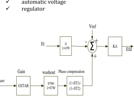
According to the well-known design method which uses CPSS, the electromechanical oscillations are damped by implementing the PSS as shown in figure 3.
Automatic devices control the generator output in voltage and frequency, in order to keep them constant according to pre established values .these devices are listed below.
automatic voltage regulator
GSTAB (1+ST1)/
(1+ST2)
STW/ 1+STW
1/
1+sTR
Σ
KAEt
Vref
Efd
Gain washout Phase compensation
+
+
-∆wr
Figure.3. Block diagram of the conventional power system stabilizer
[image:2.595.317.547.434.602.2]© 2017, IRJET | Impact Factor value: 5.181 | ISO 9001:2008 Certified Journal | Page 106 The AVR quality influences the voltage level during steady
state operation, and also reduce the voltage oscillations during transient periods, affecting the overall system stability. The parameters for the generator, AVR, excitation system, are given in the appendix below.
2.3 Fuzzy logic structure
The content of control is determined in relation to a number of data inputs using a set of equations to express the whole control process in conventional and non linear control systems.
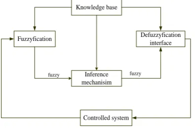
The mathematical formula for a system cannot able to express human experience, if not it is an impossible one. Fuzzy logic gives a simple interpretation for this experience in to the practical world. Fuzzy logic controller are rule based controllers that are depending on the inference rules. The basic configuration of the fuzzy logic controller has four parts shown below
.
Fuzzyfication Defuzzyfication interface Knowledge base
Inference mechanisim
Controlled system fuzzy
[image:3.595.61.259.348.478.2]fuzzy
Fig. 4 Schematic diagram of the FLC building block
1.Fuzzification – first, it is a process that read, measure, and scale the control variable (speed, acceleration) and, second, to transform the measured numerical values to the corresponding linguistic (fuzzy variables with appropriate membership values);
2.Knowledge base - this includes the definitions of the fuzzy membership functions defined for each control variables and the necessary rules that specify the control goals using linguistic variables
3.Inference mechanism – it should be capable of simulating human decision making and influencing the control actions based on fuzzy logic
4.Defuzzufication module – which converts the inferred decision from the linguistic variables back the numerical values
2.3.1.Fuzzy logic design
The fuzzy logic controller (FLC) design consists of the following five steps
1. Identification of input and output variables. 2. Construction of control rules.
3. Establishing the approach for describing system state in terms of fuzzy sets, i.e., establishing fuzzification method and fuzzy membership functions.
4. Selection of the compositional rule of inference.
5. Defuzzification method, i.e., transformation of the fuzzy control statement into specific control actions.
Selection of proper linguistic variables formulating the fuzzy control rules is very important factor in the performance of fuzzy controllers. For the present investigations generator speed deviation Δω and Acceleration Δ.ω are chosen as input signals to FLPSS.
∆ω=ω(k)-ω(k-1)=(1-z^(-1) )ω(k) (∆ω(k))/(ω(k))=(1-z^(-1)) observe that the output is
∆u=u(k)-u(k-1) by taking the z-transform of this equation results in:
=u(k)-z^(-1) u(k) =(1-z^(-1) )u(k) then
u/∆u=1/((1-z^(-1))) ,it is a discrete filter
Membership function: Each of the FLC input signal and output signal, fuzzy variables (Xj={ , ,u}), has the real line R as the universe of discourse. In any practical study, the universe of discourse is restricted to a comparatively small interval of [Xminj, Xmaxj]. The number of fuzzy sets are stated for each fuzzy variables varies according to the application. The reasonable number is an odd numbers starting from 3,5,7. Increasing the number of fuzzy sets will result in a corresponding increase in the number of rules.
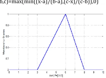
© 2017, IRJET | Impact Factor value: 5.181 | ISO 9001:2008 Certified Journal | Page 107 or more compactly. by
f(X:a,b,c)=max(min((x-a)/(b-a),(c-x)/(c-b)),0)
Figure5: Triangular Membership Function
2.The Trapezoidal function
The trapezoidal curve is a function of a vector, x, and depends on four scalar parameters a, b, c, and d, as given by
[image:4.595.77.263.125.262.2]or more compactly. by
Figure 6: Trapezoidal Membership Function
The main parts of the FLC is the rule base and the inference mechanism
The ith linguistic control rule
Ri: if is Ai and is Bi THEN Ui is Ci
where Ai and Bi (antecedent) Ci( consequent) are fuzzy variables characterized by membership functions and the composition operation can be expressed as
μB(U)=Sup[MIN(UA(x),μB(x,0) )]
where A is the known fuzzy set for the input X and B is for the inferred fuzzy set for the output.
defuzzification: converts the fuzzy output of the inference engine to crisp using membership functions similar to the ones used by the fuzzier.The performance of the FLC depends very much on the deffuzzification process. This is because the overall performance of the system under control is determined by the controlling signal (the defuzzified output of the FLC) that the system universe. From the literature there are defuzzification methods that has been proposed[12]
1.The centroid of area method(COA) :it is given by the algebraic expression.
where U is the output variable and is the membership function of the aggregated fuzzy set A with respect to U. For a continuous membership function and
for a discrete membership function .where the aggregate output MF
2.Means of maximum (Mom) method: it is the average of the maximizing U at which the MF reach maximum U.
where M={Ui/ (ui) the height of the fuzzy set } and is the cardinality of the set M
3.Centre of sums ( COS) method: cos builds the result and membership function by taking the algebraic sum of outputs from each of the contributing fuzzy sets A1,A2,A3,etc. The defuzzied value Ucos is given by
where n is the number of fuzzy sets and N is the number of fuzzy variables.
© 2017, IRJET | Impact Factor value: 5.181 | ISO 9001:2008 Certified Journal | Page 108 NB: negative big, NM negative medium, NS negative small
[image:5.595.39.284.219.313.2], ZE zero, PS positive small , PM positive medium and PB positive big. The membership functions for input and output variables are triangular. The min-max method inference engine is used; the deffuzzify method used in this FLC is centre of area. The complete set of control rule is shown below.
Table -1: Fuzzy controller rules
Each of the 49 control rules represents the desired controller response to a particular situation. The block diagram of FLC shown in matlab simulation (ANFS edit),and in figure the simulation of the surface control is presented.
3. PROPOSED SYSTEM
3.1. Modeling of STATCOM Controller
XSDT
V0
M ψ VDC
CDC IDC
VT VL VB
JXT JXTB
ILt ILB
[image:5.595.306.553.407.682.2]IL0 G
Figure 7. STATCOM connected in a single machine infinite bus power system
Figure.7 shows a single-machine infinite-bus power system installed with a FACTS device , a statcom which consists of the transformer (SDT) that connected in the low coil side with a leakage reactance xsdt, a three phase GTO-based voltage source converter (VSC) and a DC capacitor to get turn of thyrister.
The linearzed model of the power system installed with the STATCOM is derived [13] are
1
2
3
4
where 5
by substituting the linearzied currents and equation 3 in to equation5. ∆pe=k1∆δ+K2∆Eq'+KpDc∆VDc+Kpc∆c+Kpφ∆φ 6
7
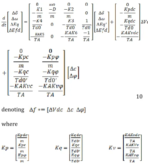
or by substitution deviation of d-axis current in this equation we can get 8 9 substituting equations 5-8 in to equation 4, we get 10
denoting
where
The linearized model of dc side voltage is from the above figure and equation
[image:5.595.52.275.420.592.2]© 2017, IRJET | Impact Factor value: 5.181 | ISO 9001:2008 Certified Journal | Page 109 where K1-K9 calculated in the linearized current
equations .
The full state system model can be obtained as follows
K1
1/2Hs+D Wo/s
K4
K2 K5
1+/ ST3+Td0
KA/ (1+STA)
Σ
Σ Σ
K6
Gpss
-+ +
+
+ -∆wr
∆Efd DEq’
KqU KqDC KPu
KVDC KVU
1/ (s+K9) K8
KPDC
K7
Σ
KEU
FLC and lead lag d/dt
+
-+
[image:6.595.303.562.95.296.2]
-∆δ
Figure 8. SIMB with STATCOM block diagram
[image:6.595.39.290.150.403.2]The block diagram shown in figure 11 shows a synchronous applied to its excitation system in the Matlab simulation machine for which the output voltage is controlled by a PSS.
Figure 9. Excitation system simulink diagram
4. SIMULATION RESULTS OF THE SYSTEM
[image:6.595.308.554.507.689.2]Figure 10: Response without excitation system
Figure 11: Response with excitation system for -ve K5
[image:6.595.41.281.508.702.2]
© 2017, IRJET | Impact Factor value: 5.181 | ISO 9001:2008 Certified Journal | Page 110 Figure 13: response with pss system for -Ve K5
Figure 14: Response with PSS system for +Ve K5
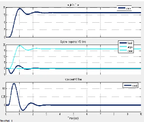
[image:7.595.38.284.329.511.2]Figure 15: Response with Fuzzy system for +Ve K5
Figure 16: System response of STATCOM with fuzzy controller
Figure 17: Comparisons of PSS and STATCOM controllers
5. CONCLUSIONS
[image:7.595.308.557.331.507.2] [image:7.595.42.281.543.745.2]© 2017, IRJET | Impact Factor value: 5.181 | ISO 9001:2008 Certified Journal | Page 111
ACKNOWLEDGEMENT
First of all I would like to express my gratitude to my advisor, DR. G.V.SIVA KRISHNA RAO , to whom I am deeply grateful for his encouragement, patience and guidance during my research. Without his support I would never have thought about the deep problems of this thesis and would never have had possibility to complete this valuable effort.
Finally, I would like to thank my friends and fellow graduate students for their sincere help and friendship.
REFERENCES
[1] P.Kundur, “Power system stability and control” New York: Tata McGraw-Hill, 1994.
[2] P.M Anderson and A. A. Fouad, “Power System Control and Stability”, Volume- I, Iowa State UniversityPress, Ames, Iowa, 1977.
[3] Foud AA, Vittal V,Power System Transient Stability Analysis Using the Transient Energy Function Method. Prentice-Hall, USA, (1992).
[4] Pai MA,Energy Function Analysis for Power System Stability. KluwerAcademic Publishers, USA, (1989).
[5] Pavella M, Muthy PG,Transient Stability of Power Systems: Theory and Practice. John Wiley and Sons, Chichester, (1994):
[6] Kundur P, Power System Stability and Control. McGraw Hill, USA, (1994).
[7] P. Hoang, K. Tomsovic. Design and analysis an adaptive fuzzy power system stabilizer. IEEE Transactions on Energy Conversion, Vol. 11, No. 2, June 1996;
[8] Wenxin Liu, Ganesh K. Venayagamoorthy, Donald C. Wunsch. Adative neural network based power system stabilizer design. IEEE 2003, page 2970-2975;
[9] Rahmatollah Hooshmand, Mahdi Banejad. Robust control design of power system stabilizer using artificial neural networks. AUPEC 2006;
[10] Hassan M. A. M., Malik O. P., and Hope G. S.,”A Fuzzy Logic Based Stabilizer for a Synchronous Machine”, IEEE Transactions on Energy conversion, vol. 6, No. 3, 1991, pp. 407-413;
[11] Hasan A. R., Martis T. S., and Sadral Ula A. H. M., „Design and implementation of a Fuzzy Controller based automatic Voltage Regulator
for Synchronous Generator”, IEEE Transactions on Energy conversion, vol. 9, No. 3, 1994, pp. 451-459
[12] Ritu Jain Asst. Professor Suresh Gyan Vihar University Jaipur, India "Power System Stability Enhancement Using Fuzzy Based Power System Stabilizer "International Journal of Research and Scientific Innovation (IJRSI) | Volume III, Issue VII, July 2016