The Use of Light Diffracted from Grating Etched onto
the Backside Surface of an Atomic Force Microscope
Cantilever Increases the Force Sensitivity
Sergey K. Sekatskii*, Mounir Mensi, Andrey G. Mikhaylov, Giovanni Dietler
Laboratoire de Physique de la Matière Vivante, IPSB, Ecole Polytechnique Fédérale de Lausanne (EPFL), Lausanne, Swit- zerland.
Email: *[email protected]
Received June 19th, 2013; revised July 22nd, 2013; accepted August 3rd, 2013
Copyright © 2013 Sergey K. Sekatskii et al. This is an open access article distributed under the Creative Commons Attribution Li-cense, which permits unrestricted use, distribution, and reproduction in any medium, provided the original work is properly cited.
ABSTRACT
A reflecting diffraction grating has been etched onto the backside of a standard cantilever for atomic force microscopy, and the diffracted light has been used to monitor the angular position of the cantilever. It is shown experimentally that for small angles of incidence and for large reflection angles, the force sensitivity can be improved by few times when an appropriate detection scheme based on the position sensitive (duolateral) detector is used. The first demonstration was performed with a one micron period amplitude diffraction grating onto the backside of an Al-coated cantilever etched by a focused ion beam milling for the experiments in air and an analogous 600 nm-period grating for the experiments in air and in water.
Keywords: Atomic Force Microscopy; Force Measurement Sensitivity; Diffraction Grating
1. Introduction
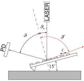
Atomic Force Microscopy nowadays is an extremely use- ful and broadly used instrument to investigate the topog- raphy of different samples with a (sub) nanometer spatial resolution and to measure interaction forces with pico- Newton sensitivity [1]. In practice, the overwhelming majority of the instruments are based on measuring the deflection angle of the laser beam reflected from the can- tilever’s backside, see Figure 1. The physical principle of this approach is that one measures as precisely as pos- sible the reflection angle , which is changing because the lever bends under the action of the interaction force between the tip and the substrate. In Figure 1, a typical experimental situation is shown: without grating, a mir- ror-like reflection of the laser beam occurs and under the action of the interaction force, which changes the angle between the cantilever and the sample (initially equal to 15˚ on the Figure 1) on the d value, the angles change all of the same amount, namely ddd0.
The aim of this Note is to attract the attention on the fact that the sensitivity of the detection scheme to change of or 0 can be essentially increased if a diffraction
grating is present on the cantilever’s backside (see Fig- ure 1). Different types of diffraction gratings can be used (see below), but here the simplest case of a flat regular grating is first considered. Let l be the grating period, n—the order of the diffraction, —the wavelength of the laser light, then the condition for an intensity maxi- mum of the reflected beam reads [2]:
sinsin0
n (1)
Here 0 is the incidence angle of the laser beam with
respect to the normal to the grating surface. The purpose of this setup is to measure in the far zone in order to determine 0 as precisely as possible (for the reason-
able cantilever bending one evidently has that the change of this angle is the same as the change of angle ;
0
d d ). Hence the derivative d d 0 or d d
should be as large as possible. From (1), it follows that
0
0 cos d
d cos
(2) This means that if one selects the angles 00˚, 90˚,
that is the normal incidence and the oblique reflection, one will obtain a large gain in sensitivity: a small change of or 0 will lead to a much larger change in .
15˚
0
[image:2.595.104.240.95.226.2]
Figure 1. Schematic of a proposed detection scheme based on the reflection of light from the diffraction grating on the cantilever backside and its detection by the position-sensi- tive detector (PD).
Therefore, the detection sensitivity can be improved up to a factor of ten-twenty (and potentially much more), because angles in the range 70˚ - 80˚ are suffi- cient.
As we have discovered in a course of work, a similar idea has been already put forward in a Japanese patent filed 18.10.1994 (in Japanese) [3] but, to the best of our knowledge, here we present its first experimental realiza- tion and also clarify some hitherto non-discussed impor- tant issues, first of all the necessity to use other than the most common in the field of split photodetector to detect the reflected light, for obtaining real improvements re- lated with this approach. This latter aspect has also been tested experimentally using an appropriate lateral effect photodetector, see below.
2. Results and Discussion
In practice, the method at hand does not bring a real im- provement of sensitivity when using a flat regular dif- fraction grating in conjunction with a standard AFM split detector (two or four quadrants photodiode) to detect the deflection signal. The problem is that the sensitivity of this detection scheme is proportional to the angular di- vergence of the reflected laser beam [1,4]. Assuming that the distance L between lever and detector is large and that the laser light spot on the lever is much smaller than the spot size a on the detector, then one can estimate the sensitivity of detection proportional to PL a, where P is the laser power. However, the angular diver- gence of the reflected beam and the spot size a are ampli- fied by the same factor cos0 cos, thus cancelling the suggested increase of the sensitivity. The same conclu- sion holds with respect to the proposal to use a cylindri- cal reflector glued onto the cantilever to improve the an- gular sensitivity [5].
Different approaches how to overcome this limitation are discussed below. Now we would like just to note that
even if a flat diffraction grating is used, the sensitivity increase of the proposed method can be still obtained in practice if a lateral effect detector (duo-lateral detector) is exploited [4]. This is due to the circumstance that to realize the high sensitivity for such a detector it is neces- sary that the light to be detected exposes almost the whole active surface of detector for which, given the fixed detector-cantilever distance, the enlarged angular spread of diffracted-reflected light in comparison with that mirror-like reflected, is really important [4]. Note also that the theoretically estimated minimum detected angle for the duo-lateral detector is a factor 2π2.5 smaller than that of a split detector [4].
Duo-lateral detector is not common in AFM field, so its use for our experimental demonstration required pre- paration of special cantilever holder and electronics. These results, as well as the data obtained in a proof-of- the-concept experiment using a standard two-quadrants photodiode detector, are presented here. In all cases, aluminum coated silicon levers CSC38 cantilevers from MicroMash, Tartu, Estonia, with the length 250 µm, width 35 µm, thickness 1 µm and typical spring constant 0.08 N/m, coating thickness 30 nm, were used.
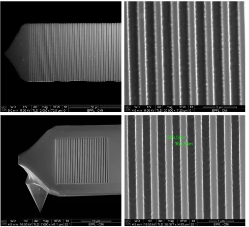
In the first experiment we used an amplitude diffrac- tion grating with a period of 1 micron etched into the backside of the AFM cantilever by the Focused Ion Beam (FIB) (see Figure 2). The grating consisted in 500 nm wide aluminum-free grooves alternating with 500 nm-wide aluminum strips. This experiment has been performed in air. Laser beam (CW He-Ne, 5 mW) was focused onto the end part of the cantilever beam by a small lens with a focal distance of 15 mm and a typical spot size of approximately 20 - 40 µm. The reflected light was detected by a two-quadrant photodiode whose signal was amplified by a differential amplifier. The sample was a standard 0.17 mm thick microscopy cover glass mounted onto a NIS-70 scanner (Nanonics, Israel), and a triangular HV signal was applied to the scanner to realize the periodical engagement/disengagement of the contact between the tip and sample. Scan ranges from 8 to 35 microns were used, and approach/retraction curves were recorded by a PC using a customarily written Lab- View program. The experiment was designed in order to be able to compare alternatively the mirror reflection with the diffracted reflection from the grating on the same sample. Different incidence angles 0 were tested,
but below we report the results obtained for 018˚, 70˚, where the direct comparison is possible. This incidence angle was easy to control by observing the n = −1 order diffraction beam, which for our case was very close to the auto-collimation condition: 0 if
0
18.4˚.
Figure 2. SEM images of the grating formed at the backside surface of CSC38 AFM lever by the focused ion beam etching method. Up: 1 micron-period grating, down: 600 nm-period grating.
fluence of the PL a factor in order to test the effect of d d 0 itself. For this, we vary the focusing condi-
tions and adjusted the position of a focused laser spot with respect to the cantilever in such a manner that the powers and sizes of the laser light spots “grating-re- flected” and “mirror-reflected” from the cantilever were as close to each other as possible. (The typical laser po- wer in both reflected spots was around 0.5 - 0.8 mW and sizes agrat, amirr, measured at a distance of 10 cm from
the cantilever, were 8 - 12 mm). Then the photodiode with the diameter of 25 mm was placed at a distance 2 - 3 cm from the cantilever and approach-contraction curves were recorded cyclically “measurement of the
grating reflection-measurement of the mirror reflection, etc”. with an appropriate readjusting of the laser with respect to the cantilever but without changing the po- sition of cantilever and sample to be sure in the re- producibility of the data; see the results of our testing in Figure 3.
Figure 3. Approach/contract curves recorded for the grat- ing (up) and mirror (bottom) reflections from the cantile- ver. The continuous z-coordinate (recalculated from the time using the calibrated scanning rate) is used and the moments of the change of the scanning direction are not shown.
related with the measurement of experimental parameters involved (first of all, the reflected light spot sizes and, obviously, the distribution of the light intensity through- out the spot is not as homogeneous as required for a pre- cise comparison).
It was not a problem to work with the larger grating reflection angles, up to 80˚, but the quantitative comparison of corresponding approach curves with those obtained for the mirror reflection in the same conditions was not possible because the parameters of two reflected beams differed too much.
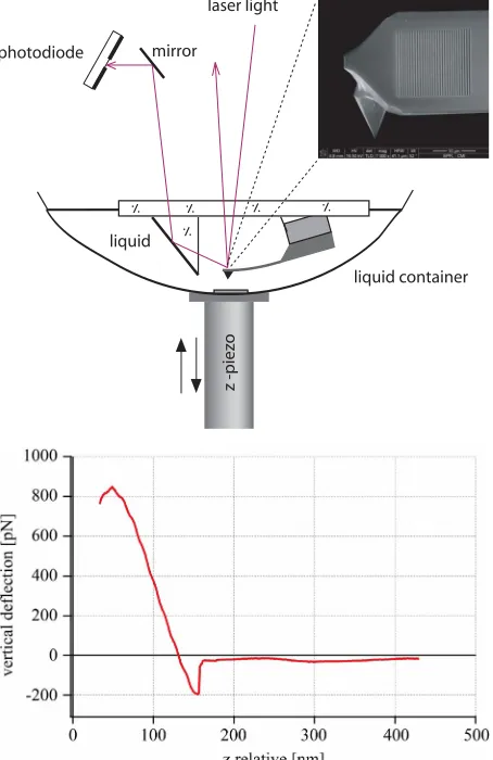
Similar experiment was aimed at proving the method under liquids in order to assess its sensitivity for single molecule force spectroscopy experiments, see e.g. re- views [6-8]. For this, a Nanoscope AFM head (Brucker Corp., USA) with the built-in two-quadrant photodiode and laser diode (wavelength 650 nm) was used.
A liquid cell modified with an additional metal-coated
prism to reflect the grating-reflected light (Figure 4) was prepared for this experiment. Hence, signals caused by a light beam diffracted from the grating and mirror-like reflected from it were both measured just by a slight re- adjustment of the position of the mirror and of the photo- diode without any other change of the set up. An addi- tional complication of this experiment was caused by the index of refraction of water (n = 1.33) that reduces the wavelength to ca. 489 nm necessitating the use of grat-
photodiode
z -piez
o
.
I. I.. I.. I..
. I.
laser light
mirror
liquid
liquid container
[image:4.595.311.538.219.569.2]ings with a period essentially smaller than 1 micron. A 600 nm period grating was selected for this experiment, but it turned out that the fabrication of this grating re- quires the highest possible resolution of the FIB etching process which was possible only on smaller area (Figure 2) limiting the efficiency of grating reflection. Using this grating and the liquid cell, approach/retraction curves of the AFM tip on a mica surface showing the characteristic adhesion forces of a few hundreds of pN have been suc- cessfully recorded in water. In the best cases, the slope of the linear part of these approach curves recorded for the first order grating reflection attains roughly the same va- lue as for the mirror-like reflection, which is quite good given all the negative factors discussed above.
In a next series of experiments, both 1 micron- and 600 nm-period gratings etched onto the cantilever back- side were tested in air exploiting the detection of dif- fracted light by high linearity position sensing detector SL5-1 (duo-lateral photodiode) of UDT Sensors Inc., USA, with the size of an active area 5 × 1 mm. This photodiode was used together with the customarily pre- pared amplifier recommended for these purposes by many sources, e.g. by Hamamatsu Company [9]. Espe- cially convincing results were obtained when detecting the reflection of a He-Ne laser beam from 600-nm period grating. This grating supports only one single n = −1 order of diffraction provided an incidence angle 03.1˚.
Correspondingly, using an incidence angle 03.3˚ one gets a diffracted beam at the angle 85˚ (at the angle 80˚ for 04.0˚) which gives the value of cos 0
cos
equal to 11.5 (respectively to 5.7). Experimentally, for such a configuration we observed effective reflection even for the aforementioned large diffraction angles (up to 1.5 mW of light power has been measured for a beam diffracted at the angle of 80˚ when the laser was focused with a lens with a focal distance of 25 mm), and almost whole surface of the active area of duo-lateral photodi- ode has been exposed to light for cantilever-detector dis- tance about 30 mm. These experimental results hold much promise for an application of such scheme in real single molecule force spectroscopy experiment which preparation is currently underway in our laboratory; for this field cf. e.g. our publications [10,11].
3. Conclusions and Further Suggestions
To conclude, we would like to stress again that an idea to use a diffraction grating etched onto the reflective back- side surface of an AFM cantilever to improve the force sensitivity of the instrument has been for the first time successfully experimentally tested in both air and liquid environments, using both standards for the field split
photodetector and lateral effect detector. In our opinion, such a testing does create interesting opportunities for further use of this approach for AFM researches in prac- tically important areas.
The perspectives of the method can be drastically im- proved when more complicated specially designed grat- ings are formed onto the backside of the cantilever. Dif- ferent opportunities can be envisaged and they will be considered elsewhere in details. As an example, one can use focusing concave gratings, which nowadays are broad- ly applied not only for spectrometry [2] but also in laser resonators [12], as spectral multiplexers/demultiplexers in optical networks, see e.g. [13]. For these gratings, the effect of an increased of angular sensitivity is decoupled from the initial angular divergence of the light source. Note also that for the quite practical Rowland circle radii of approximately 2 cm (cf. [13]), spot sizes on the canti- lever of approximately 30 microns, and the depth of the profiling of the cantilever are necessary to realize the re- quired concavity amounts to the value of only 20 nm. This is smaller than the typical thickness of the reflecting metal coating deposited onto the backside of a cantilever, and thus the possibility to prepare these gratings seems evident. Even more promising is the possibility to use a specially designed non-fully periodic sub-wavelength gratings enabling the focusing of an incident light with high reflectivity (see the recent paper [14] and references therein).
A few other possibilities to improve the presented ap- proach also deserved to be mentioned here. In order to increase further the angle , one can imagine to detect the opposite diffraction spot as it is indicated in Figure 1, which has an angle that can approach the maximal value of 90˚ being not obstructed by the sample surface. (This supposes that the photodiode is placed on the side of the chip carrying the lever: at present this is not a vi- able solution because the chip is obstructing the light beam, but necessary modifications of chip design should not pose serious problems).
If desirable, known methods to increase the reflectivity (for example, using special forms of grating grooves [2]) can be also used. Multiple diffracted beams from an ap- propriately designed grating could be simultaneously re- corded and cross-measurement data could be used for improving the precision of the force and position deter- mination.
Figure 5. 720 nm-period grating etched onto the backside of the ultra-short USNMCB-5 MHz cantilever, NanoWorld AG, Neuchatel, Switzerland, specially designed for high speed AFM applications and having the sizes 10 × 5 microns.
widths down to 0.5 - 1 micron or even less could be used, again because the substrate reflected beam does not dis- turb the measurements. These narrow cantilevers would enable us to decrease drastically the spring constant, which is important for many applications, especially for very high speed imaging. Such a possibility is illustrated in Figure 5, where 720 nm-period grating etched onto the backside of the ultra-short USNMCB-5 MHz canti- lever, NanoWorld AG, Neuchatel, Switzerland, specially designed for high speed AFM applications and having the sizes 10 × 5 microns, is presented. Efficient enough grating-like reflection of focused He-Ne laser beam from this cantilever (up to 0.4 mW of reflected light power for a laser beam focused with a lens with the focal distance of 15 mm) has been observed experimentally.
To conclude, we would like to mention a few papers where using of diffraction grating in combination with AFM was reported [15-18]. However, in these works a grating has been explored as an interferometer: a photo- diode, placed in a certain position, measures a light inten- sity, which changes together with the change of the dis- tance grating—photodiode due to the interference be- tween the light beam directly passed via the grating (or mirror-reflected by it) and the light beam corresponding to certain (usually n = 1) diffraction order in reflection or transmission. No effect of the increase of the angular/ force sensitivity considered in our note was used.
4. Acknowledgements
The authors thank M. Pavius and S. Clabecq, EPFL, for the focused ion beam etching preparation of diffraction
gratings and M. Burri, NanoWorld AG, for a kind gift of USNMCB-5 MHz ultra-small cantilevers. The financial support of Swiss National Science Foundation (grant No. 200021-137711) is gratefully acknowledged.
REFERENCES
[1] D. Sarid, “Scanning Force Microscopy,” Oxford Univer- sity Press, New York, 1991.
[2] M. Born and E. Wolf, “Principles of Optics,” Pergamon Press, London, 1959.
[3] Japan Patent No. 6-289036, 1994.
[4] A. Garcia-Valenzuela, “Limits of Different Detection Schemes Used in the Optical Beam Deflection Method,” Journal of Applied Physics, Vol. 82, No. 3, 1997, pp. 985-988.
[5] A. Yarai, Y. Fukunaga, K. Sakamoto and T. Nakanishi, “High-Frequency and High-Gain Amplification of Photo- thermal Beam Deflection Angle Using Cylindrical Re- flection Mirror,” Japanese Journal of Applied Physics, Vol. 33, No. 5B, 1994, pp. 3251-3255.
[6] J. Zlatanova, S. M. Lindsay and S. H. Leuba, “Single Molecule Force Spectroscopy in Biology Using the Atomic Force Microscope,” Progress in Biophysics and Molecular Biology, Vol. 74, No. 1-2, 2000, pp. 37-61. [7] J. W. Weisel, H. Shuman and R. I. Litvinov, “Protein-
Protein Unbinding Induced by Force: Single-Molecule Studies,” Current Opinion in Structural Biology, Vol. 13, No. 2,2003, pp. 227-235.
[8] C. K. Lee, Y. M. Wang, L. S. Huang and S. Lin, “Atomic Force Microscopy: Determination of Unbinding Force, Off Rate and Energy Barrier for Protein—Ligand Inter- action,” Micron, Vol. 38, No. 5, 2007, pp. 446-461. [9] “Two-dimensional PSD,” 2013.
http://www.hamamatsu.com/resources/pdf/ssd/s1880_s20 44_kpsd1015e06.pdf
[10] S. K. Sekatskii, M. Favre, G. Dietler, A. G. Mikhailov, D. V. Klinov, S. V. Lukash and S. M. Deyev, “Force Spec- troscopy of the Barnase—Barstar Interaction at the Sin- gle-Molecule Level,” Journal of Molecular Recognition, Vol. 23, No. 6, 2010, pp. 583-588.
[11] F. Benedetti, C. Micheletti, G. Bussi, S. K. Sekatskii and G. Dietler, “Non-Kinetic Modeling of the Mechanical Unfolding of Multimodular Proteins: Theory and Experi- ments,” Biophysical Journal, Vol. 101, No. 6, 2011, pp. 1504-1512.
[13] J. Song, N. Zhu, J.-J. He and S. He, “Etched Diffraction Grating Demultiplexer with Large Free Spectral Range and Large Grating Facets,” IEEE Photonics Technology Letters, Vol. 18, No. 24, 2006, pp. 2695-2697.
[14] D. Fattal, J. Li, Z. Peng, M. Fiorentio and R. G. Beau- soleil, “Flat Dielectric Grating Reflectors with Focusing Abilities, Nature Photonics, Vol. 4, No. 7, 2010, pp. 466- 470. [15] G. G. Yaralioglu, A. Atalar, S. R. Manalis and C. F.
Quate, “Analysis and Design of an Interdigital Cantilever as a Displacement Sensor,” Journal of Applied Physics, Vol. 83, No. 12, 1998, pp. 7405-7415.
[16] T. Sulchek, R. J. Grow, G. G. Yaralioglu, S. C. Minne, C.
F. Quate, S. R. Manalis, A. Kinaz, A. Aydine and A. Alalar, “Parallel Atomic Force Microscopy with Optical Interferometric Detection,” Applied Physics Letters, Vol. 78, No. 12, 2001, pp. 1787-1789.
[17] N. A. Hall and F. L. Degeterkin, “Integrated Optical Inter Ferometric Detection Method for Micromachined Capaci- tive Acoustic Transducers,” Applied Physics Letters, Vol. 80, No. 20, 2002, pp. 3859-3861.
[18] F. L. Degeterkin, A. G. Onaran, M.Balantekin, W. Lee, N. A. Hall and C. F. Quate, “Sensor for Direct Measure- ment of Interaction Forces in Probe Microscopy,” Applied Physics Letters, Vol. 87, No. 21, 2005.