J. Micromech. Microeng.13(2003) S11–S16 PII: S0960-1317(03)59936-3
Electronic interface design for an
electrically floating micro-disc
M V Gindila and M Kraft
Microelectronics Research Center, University of Southampton, SO17 1BJ, UK
E-mail: [email protected]
Received 24 February 2003, in final form 21 March 2003 Published 13 June 2003
Online atstacks.iop.org/JMM/13/S11
Abstract
The design of an electronic interface for an electrically floating micro-disc is presented. The system, based on a second order electromechanical– modulator, can be used as a multi-axis capacitive accelerometer with the proof mass levitated by electrostatic forces. A synchronous detection scheme, used to sense the position of the proof mass, has been designed, simulated in PSpiceTMand successfully implemented on a PCB. The
interface contains a differential pick-off with no ohmic connection to the proof mass, which distinguishes the circuit from typical sensing circuits for MEMS capacitive accelerometers. A noise analysis of the pick-off circuit was performed, and an electronic equivalent model of the sensing circuit has been developed and used to analyse the linearity of its transfer function. The linearity of the sensing circuit was confirmed experimentally using the PCB implementation.
1. Introduction
In typical micromachined accelerometers the proof mass is attached to the substrate by an anchor [1], which makes their characteristics dependent on the fabrication process tolerances and difficult to tune once the device has been fabricated. Electrostatic levitation is a method to eliminate the need for a mechanical connection and is well suited to microelectromechanical systems (MEMS). On this approach, relatively little research has been done; nevertheless, there are many potential applications including inertial sensors [2], micro-motors [3] and frictionless bearings [4]. An electrostatically levitated micro-motor with the function of a multi-axis accelerometer is reported in [5], and also an electrostatically levitated spherical three-axis accelerometer was developed by Ball Semiconductors [6].
This paper presents an electronic interface for a multi-axis capacitive micromachined accelerometer, for which the proof mass consists of a micro-disc levitated by electrostatic forces. The system is able to detect linear, out-of-plane acceleration and angular acceleration about the two in-plane axes. Compared to conventional force-balanced accelerometers, the effective spring constant depends only on the feedback voltage of the system due to the electrostatic levitation of the proof mass. By changing the feedback
voltage, the spring constant can be readily adjusted, thus the sensitivity and the bandwidth of the system can be tuned according to the sensor application. Furthermore, the system offers uniform sensitivity in all degrees of freedom, which is difficult to achieve in conventional multi-axis accelerometers. Nevertheless, this approach imposes more severe requirements on the electronic interface design. To ensure the control of the disc position in three degrees of freedom, the accelerometer is embedded in a second order electromechanical – modulator. This structure offers good linearity, good stability and results in direct digital output of the system. Furthermore, it ensures that high resolution with a simple architecture can be achieved [7].
Capacitive sensor interfaces use different methods to convert the capacitance value into a voltage such as voltage detection with a unity gain buffer [8], or charge integration [9]. In this application, electrostatic levitation implies no ohmic contact to the proof mass, hence the capacitive sensing circuits used in conventional MEMS accelerometers are not suitable [10] and a novel design is required.
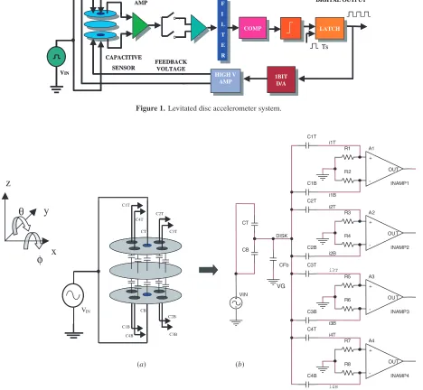
The block diagram of the system is presented in figure1. The top and bottom plates of the sensor are excited with a high frequency signal VIN, and four pairs of electrodes
DEMODULATOR CAPACITIVE SENSOR F I L T E R F I L T E R Ts 1BIT D/A 1BIT D/A HIGH V AMP HIGH V AMP LATCH LATCH COMP COMP VIN FEEDBACK VOLTAGE DIGITAL OUTPUT PICK-OFF AMP DEMODULATOR CAPACITIVE SENSOR F I L T E R F I L T E R Ts 1BIT D/A 1BIT D/A HIGH V AMP HIGH V AMP LATCH LATCH COMP COMP VIN FEEDBACK VOLTAGE DIGITAL OUTPUT PICK-OFF AMP
Figure 1.Levitated disc accelerometer system.
0 R3 A1 INAMP1 + -OUT CT C1T i2T C2B R6 0 C3B C4T 0 i3B A3 INAMP3 + -OUT R5 DISK R7 i4T 0 R1 i1T A2 INAMP2 + -OUT C4B R2 CB i4B C2T i2B R4 i3T A4 INAMP4 + -OUT 0 R8 C3T C1B VIN VG CFb i1B (a) (b) C4B C2B CT CB C3B C1B C1T VIN C3T C2T C4T
φ
x
θ
z
y
Figure 2.(a) Levitated disc accelerometer and (b) equivalent electronic model of the sensing circuit.
a low noise differential pick-off amplifier, which converts the differential capacitance between the top and the bottom plate into a differential voltage. The output of the amplifier is fed to a synchronous demodulator, followed by a low pass filter.
The mechanical sensing element is equivalent to a double integrator, which introduces a phase lag in the forward path, hence a phase compensator is needed to ensure system stability. After the compensator, the signal is applied to a 1-bit A/D quantizer implemented with a comparator and a latch. The latch is controlled by a clock signal, which determines the sampling frequency,fs, of the modulator.
The sampling frequency has to be much higher than the bandwidth of the sensor to ensure a high sensor resolution. Considering a sensor bandwidth of 1 kHz, a sampling frequency of 100 kHz was chosen. The latch output is a pulse density modulated bitstream, which contains information
about the displacement of the proof mass. In the feedback path, this signal is applied to a 1-bit D/A converter and further to a high voltage amplifier which provides the voltage used to control the feedback electrodes. This produces an electrostatic force, which acts in opposite direction to the disc displacement, and thus the disc is kept close to the equilibrium position.
2. Disc position measurement circuit
2.1. Sensing circuit
one sensing electrode and two feedback electrodes. Since this section is focused on the sensing part of the electronic interface, for simplicity the feedback electrodes are omitted in figure 2(a). The feedback electrodes of the same quarter are always controlled by voltages of the same magnitude and opposite polarity. From the sensing point of view, this implies no charge injection from the feedback electrodes to the disc, hence the feedback part of the sensor can be represented by an equivalent capacitor CFb, between the disc and virtual ground
(VG in figure 2(b)). Its value is given by the sum of all feedback capacitances.
Figure2(b) shows the equivalent electronic model for the sensing circuit. A high frequency signal VIN of 1 MHz is
applied to the excitation electrodes which, together with the disc, form the capacitancesCTandCB. CapacitancesCkTand
CkB(k =1,. . ., 4) are formed by the four pairs of sensing
electrodes and the disc. These are used for detection of the disc position in three degrees of freedom, and have a nominal value of approximately 1 pF. The pick-off circuit contains four pick-off amplifiers, one for each pair of sensing electrodes. 2.2. Linearity analysis
The linearity of the transfer function of the sensing circuit is an important requirement for the design of the system, since the differential output voltage of the sensing circuit should be proportional to the differential capacitance. Therefore, a linearity analysis of the transfer function, V/C, of the equivalent sensing circuit presented in figure 2(b) was performed. It can be shown that the differential voltage at the pick-off amplifier inputVk,k=1,. . ., 4, can be expressed as a function of capacitances, excitation signal amplitudeVIN,
excitation signal frequency and input resistors at the pick-off amplifierR=Rk,k=1,. . ., 8, as
Vk=CK
1 + jω(CKT+CKjBωR)R+ω2CKTCKBR2
VIN
× CT+CB
CT+CB+
4
k=1
CkT
1+jωCKTR+ CkB 1+jωCKBR
+CFb
,
K=1, . . . ,4. (1)
The sensing capacitances are a function of the disc movement (vertical displacementzand the tilt angles ‘φ’ and ‘θ’, with respect to thexandyaxes [11]). When varying z,φandθ, the expression inside the modulus of equation (1) does not remain constant which means that the dependence between Vk and the differential capacitance Ck = CkT − CkB
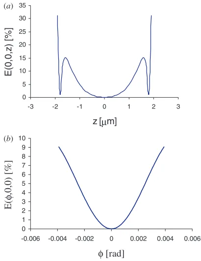
(k= 1, 4) is nonlinear. To see the influence ofz,φ andθ on the nonlinearity error, and to determine critical situations, when this error is maximum, several different cases were analysed using MathcadTM. The gap between the electrodes
was assumed to bez0=2µm, and the radius of the electrodes
R= 500 µm; the maximum tilt angle φ or θ can then be expressed as
φmax=arctan
z0 R
=0.004 rad. (2) Figure3(a) shows the nonlinearity error,E(z,φ,θ), whenz varies and the tilt anglesφ andθ are zero. For the second case, figure3(b),zis maintained constant and one of the tilt
0 1 2 3 4 5 6 7 8 9 10
-0.006 -0.004 -0.002 0 0.002 0.004 0.006
φ [rad]
E(φ
,0,0) [%]
0 5 10 15 20 25 30 35
-3 -2 -1 0 1 2 3
z [µm]
E(0,0,z) [%]
(a)
[image:3.595.307.512.70.337.2] [image:3.595.49.284.324.534.2](b)
Figure 3.Non-linearity error,E[%] for (a)φ=θ=0 and z∈[−2;2]µm and (b)φ∈[−0.004,0.004] rad, θ=0 andz=0.
0 0.2 0.4 0.6 0.8 1 1.2
-0.6 -0.4 -0.2 0 0.2 0.4 0.6
z [µm]
Ε(φ,θ,
[image:3.595.309.513.386.509.2]z) [ %]
Figure 4.Non-linearity error,E[%] for small displacements of the disc,z∈[−0.5;0.5]µm andφ=θ=0.
anglesφvaries within the maximum values, while the other is zero.
Comparing figure3(a) with figure3(b) it can be noticed that the nonlinearity error is influenced more by the vertical displacement than the tilt, especially for large displacements of the disc.
[image:3.595.49.283.452.546.2]-15 -10 -5 0 5 10 15
-20 -10 0 10 20
∆C(0,0,z) [pF]
V(0,0,z) [V]
[image:4.595.57.272.67.207.2]TF linear TF
Figure 5.The transfer function of the sensing circuitV /C, for z∈[−2;2] andφ=θ=0.
values for the nonlinearity error, about 0.15%, which can be neglected.
The transfer function characteristic of the sensing circuit is illustrated in figure5. This presents the differential voltage Vversus the differential capacitanceC1=C1T−C1B, for a
variation ofzwithin the maximum values, and forφ=θ=0. It can be noticed that, for small displacements, the characteristic is linear.
2.3. PSpice model and simulations
The capacitive sensing interface is based on a synchronous detection scheme, which consists of a pick-off circuit followed by a demodulator and a low pass filter. Synchronous detection scheme makes use of chopper stabilization technique to cancel the offset and low frequency noise of the pick-off amplifier [12]. The pick-off circuit shown in figure 2 consists of a bridge and an instrumentation amplifier (in-amp). Since there
50us 100us 150us 200us 250us 300us
V(Cb1:4,HB1:in1) - 20uV
0V 20uV
SEL>>
V(HB1.BL0.1) 2.0mV
2.5mV 3.0mV
V(VCt : +) 1.00000V
1.00002V 1.00004V
Time
20uV
-20uV
(a)
(b)
(c)
0s
Figure 6.(a) The linear control voltage for the sensing capacitances; (b) the output of the low pass filter after demodulation and (c) the differential input signal of the in-amp.
are four pairs of sensing electrodes, four identical circuits are used. The bridge is formed by a pair of sensing capacitances and two resistors placed between the in-amp inputs and ground. The resistors convert the current from the sensing capacitor (e.g.i1T) into a voltage, and set up the dc level at the amplifier
input. Their value was chosen to avoid signal attenuation on one hand, and to minimize thermal noise contribution on the other.
The in-amp, consisting of three low noise precision op-amps OPA604, has very high impedance at both of the inputs, a stable amplification of 35 dB for the differential signal and high common mode rejection ratio. The output signal of the amplifier is demodulated using an IC AD734 and then applied to a second order active low pass filter. The cut-off frequency of the filter is chosen above the clock frequency of the comparator, for a correct operation of the–modulator, and below the excitation signal frequency for appropriate filtering after demodulation. To detect and control the position of the disc in three degrees of freedom four–modulators are used, one for each quarter of top and bottom plates of the sensor.
The pick-off circuit has been implemented in Orcad CaptureTMand simulated in PSpiceTMA/D. To simulate the
variation of the sensing capacitance in CaptureTM, a variable
impedance circuit controlled by a linear voltage was used. Considering a peak-to-peak amplitude of 20µV for the control voltageVC1T(figure6(a)) and a nominal valueC1Trefof 1 pF
for the sensing capacitances, a differential capacitive variation of 20 aF (C1T = C1TrefVC1T) results. This produces a
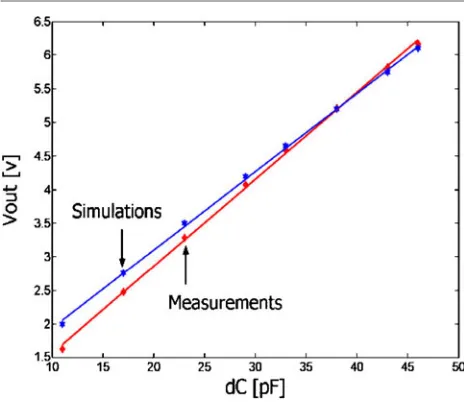
[image:4.595.88.496.489.723.2]Figure 7.Output voltage of the pick-off circuit versusC, forC
variations within 10% of the maximum range.
equivalent input noise floor of 40 nV Hz−1/2 for the
pick-off amplifier. For a calculated sensitivity of 0.5 µV aF−1,
this limits the capacitive measurement resolution to 1 aF.
3. Experimental results
The linearity of the pick-off circuit has been tested experimentally. Considering larger radius for the electrodes than the one given in the section 2.2, the calculated value for the nominal sensing capacitance is 2.3 pF. For tests, only fixed capacitors were used instead of sensing capacitances and the change in capacitance is implemented using an adjustable capacitor. Assuming that the movement of the disc is maintained within 10% of the maximum range, the maximum C to be measured is 0.46 pF. Measuring capacitive variations in the range from 4.6 pf down to 23 fF (1% of the nominal value) is difficult to realize experimentally. Therefore, the nominal value has been increased to 230 pF and the excitation signal frequency decreased to 10 kHz so that the impedance of the sensing element remains constant. Thus, capacitive variations from 46 pF down to 2.3 pF are achieved, which are easier to realize experimentally. Measurements have been carried out in this range, using two fixed capacitances with the nominal value of 230 pF and one adjustable capacitor, connected in parallel to one of the fixed capacitors. An excitation signal with an amplitude of 0.5 V and a frequency of 10 kHz was applied at the input of the capacitive network and the adjustable capacitor was used to produce theCvariations. Figure7presents the results of the PSpiceTMsimulations and
the measurement results for C variations between 10 and 46 pF. The measurement results are represented by stars and the simulation results by diamonds. Both are compared with their best linear approximation (solid line in figure7), which was calculated in MatlabTMusing the polynomial approximation
functions called polyfit and polyval. Although there is an offset and a gain discrepancy between the measurements and the simulations, which increases inversely proportional toC,
the results show a maximum nonlinearity error of 1% of the full-scale range.
This error is much larger than the maximum nonlinearity error calculated in MathcadTMfor movement of the disc within
10% of the maximum range. However, a nonlinearity error below 1% is difficult to obtain experimentally, as the accuracy of the measuredCdepends on the accuracy and the stability of the fixed capacitors.
4. Conclusions
The design of an electronic interface for electrostatically levitated disc accelerometer is presented. The signal detection part of the interface, based on a synchronous detection scheme, has been designed and simulated using PSpiceTM. This part
of the interface has been also successfully implemented and tested on a PCB board. A new type of position measurement circuit has been developed as conventional circuits for capacitive accelerometers are unsuitable for this application, since the proof mass is electrostatically floating. A PSpiceTM
noise analysis of the pick-off amplifier was performed and showed an equivalent input noise of 40 nV Hz−1. Sensitivity
of the pick-off circuit was calculated at 0.5µV aF−1, which is
equivalent to a capacitive sensing resolution of 1 aF.
An equivalent electronic model for the sensing circuit was developed and used to analyse the linearity of its transfer functionV/C. The linearity analysis shows that for large displacements of the disc, the nonlinearity error depends more on the vertical displacement than on the tilt, and for small displacements this error is very small. When electrostatic forces are applied to keep the displacement of the disc within 10% of the maximum range, the analysis shows a nonlinearity error of about 0.15%, which can be neglected. PSpiceTM simulation results and measurements on a PCB board show a nonlinearity error of 1% for a movement of the disc within 10% of the maximum range.
References
[1] Tay F E H and Logeeswareen V J 2000 Differential capacitive low-g microaccelerometer with mg resolutionSensors
Actuators8645–51
[2] Josselin V, Touboul P and Kielbasa R 1995 Capacitive detection scheme for space accelerometers applications
Sensors ActuatorsA42467–73
[3] He G, Chen K, Tan S and Wang W 1996 Electrical levitation for micromotors, microgyroscopes and
microaccelerometersSensor ActuatorsA54 741–5
[4] Kumar S, Cho D and Carr W N 1992 Experimental study of electric suspension of microbearingsJ. Microelectromech.
Syst.123–30
[5] Fukatsu K, Murakoshi T and Esashi M 1999 Electrostatically levitated micro motor for inertia measurement system
Transducer ’993P2.16
[6] Toda R, Takeda N, Murakoshi T, Nakamura S and Esashi M 2002 Electrostatically levitated spherical 3-axis
accelerometerMEMS 2002 IEEE Int. Conf. (New Jersey)
pp 710–3
[7] Kraft M and Evans A 2000 System level simulation of an electrostatically levitated discProc. 3rd Conf. on Modeling and Simulation of Microsystems (San Diego, March 2000)
[8] Boser B E and Howe R P 1996 Surfaces micromachined accelerometerIEEE J. Solid-Sate Circuits31336–57 [9] Lotters J C, Olthius J C, Veltnik P H and Bergveld P 1999 A
sensitive differential capacitive to voltage converter for sensors applicationsIEEE Trans. Instrum. Meas.4889–96 [10] Lemkin M A 1997 Micro accelerometer design with digital
feedback controlPhD ThesisU.C. Berkeley
[11] Houlihan R P and Kraft M 2002 Modeling of an accelerometer based on a levitated proof massJ. Micromech. Microeng.12 495–503
![Figure 5. The transfer function of the sensing circuitz �V/�C, for ∈ [−2; 2] and φ = θ = 0.](https://thumb-us.123doks.com/thumbv2/123dok_us/1009553.615719/4.595.88.496.489.723/figure-transfer-function-sensing-circuitz-v-c-f.webp)