© 2019, IRJET | Impact Factor value: 7.211 | ISO 9001:2008 Certified Journal
| Page 3076
PERFORMANCE VERIFICATION OF AMBA MULTI-MASTER AHB BUS
USING SYSTEM VERILOG
Deepthi V. D
M. Tech student, VLSI&ES, Govt. Engineering College Idukki, Kerala, India
---***---Abstract -
Recently, VLSI technology has improvedsignificantly and more transistors can be integrated into a chip. A System on-Chip design have number of blocks are integrated on a single chip. While multiple blocks are integrating in single IC they required powerful communication architecture to access their functionality. In order to fulfill their requirements that is possible only by on chip bus Architecture. Since on chip bus (OCB)is often the bottle neck of a system, a good OCB protocol plays an important role. Different companies has different on-Chip Bus architectures but one of the most preferable architecture is AMBA by ARM. AMBA has three buses i.e., Advanced System Bus(ASB), Advanced Peripheral Bus(APB), Advanced High Performance Bus(AHB).Among these buses AHB has high performance, high band width and for high clock frequency system modules so, system designers choose AHB as their first choice. AHB is an OCB which adopts traditional bus architecture. The problem occurs while multiple masters are trying to access a single bus and then resolution occurs as a big issue in System-On- Chip (SOC). In order to resolve the resolution problem that depends on system performance. AMBA Protocol use logical assignment to masters based on their priority they access the bus to transmit data. Arbiter block is important to decide which master get access to bus based on arbitration algorithm. The purpose of the arbitration algorithm is to assure that at one time only one master get access to the bus then remaining masters are should be idle state until they are granted by bus. Modelsim mentor graphics tool is used for the overall Design and verification of AMBA AHB Protocol with single master single slave, multi master multi slave. The verification method used in this project is "UVM"(Universal Verification Method), and also used "Functional Coverage". Finally, we measure performance latency of AHB bus and baud rate of USART peripheral while connecting to the STM32 controller.
Key Words
:
AMBA, AHB, Single and multi-master slave
mode, UVM verification, USART, Latency and baud rate.
1. INTRODUCTION
The Advanced Microcontroller Bus Architecture (AMBA) defined by ARM is a widely used open common place for associate on-chip bus system. This standard aims to ease the component design, by permitting the mix of inter changeable parts within the SoC style [1]. It promotes the employ of holding parts, so a minimum of a neighborhood of the SoC style will become a composition, rather than a complete rewrite every time. The AMBA standard defines different
groups of busses AHB (Advanced High-performance Bus), ASB (Advanced System Bus), and APB (Advanced Peripheral Bus). AHB is used for high-performance, high-clock frequency system architecture. Typical applications are ARM core and high-speed RAM inside the system, Nand Flash, DMA, Bridge links. The APB is used to connect external devices and has low performance requirements, while considering low power consumption. AMBA bus-based microcontrollers typically consist of a high-performance system hub bus (AHB or ASB) that supports external memory bandwidth, including CPUs, on-chip memory, and other direct data access (DMA)devices. This bus provides a high band width interface for most of the transmissions between the above units.
Fig-1: AMBA Bus
1.1 ASB Bus
The ASB (Advanced system bus) specification is used for defining high performance bus used in embedded microcontrollers having 16 and 32-bit. It is a high-performance pipelined bus which can provide access
to
multiple masters. Flow of essential operations of ASB is:• Master gets into contact with bus.
• Arbiter determines master’s status.
© 2019, IRJET | Impact Factor value: 7.211 | ISO 9001:2008 Certified Journal
| Page 3077
• For selecting a bus slave, a decoder uses theaccurate address lines.
• Then, acknowledgement is given back to the bus master by the slave.
1.2 APB Bus
The Advanced Peripheral Bus (APB) is used for connecting low bandwidth peripherals. It is a simple non-pipelined protocol that can be used to communicate (read or write) from a bridge/master to a number of slaves through the shared bus. The reads and writes shares the same set of signals and no burst data transfers are supported.
1.3 AHB Bus
AHB may be a new generation of AMBA bus that is meant to handle the necessities address the requirements of high-performance synthesizable design styles. It is a superior system bus that supports multiple bus masters and provides high-bandwidth operation. AMBA AHB implements the features needed for superior, high clock frequency systems including:
• Burst transfers.
• Split transactions.
• Single-cycle bus master relinquishing.
• Single-clock edge operation.
• Non-tristate implementation.
• Wider information bus configurations (64/128 bits).
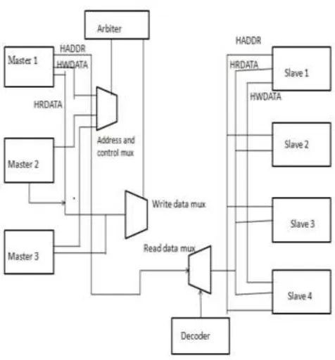
Arbitration to decide on subsequent bus master uses a round robin arbitration algorithmic rule [2]. This ensures that no master gets starved. When a master has locked the bus, the round robin arbitration is overridden and the master with the lock retains highest priority to the bus [3]. The AMBA AHB bus protocol is designed to be used with a central multiplexor interconnection scheme. Using this scheme all bus masters drive out the address and control signals indicating the transfer they wish to performand the arbiter determines which master has its address and control signals routed to all of the slaves. A central decoder is also required to control the read data and response signal multiplexor, which selects theappropriate signals from the slave that is involved in the transfer.
2. DESIGN SPECIFICATION
In our design we first take one Master and one Slave configuration. Signals travelling from Master to Slave are the HADDR, HWRITE, HSIZE, HBURST, HWDATA and HTRANS. Both the master and the slave get the clock and reset signals. The decoder provides select lines for the selection of slaves.
In our design, we have just one select line from the decoder to the slave. When this line is activated, the master communicates with the slave. Output of the Slave is HRDATA, HREADYOUT and HRESP. These signals are going to the Multiplexer and in return, the Multiplexer provides signals to the Master. These are the HRESP, HREADY and HRDATA. This block is our top design module. From outside this rectangular block, we are providing external input and output signals such as i_HADDR, i_HWRITE, i_HSIZE, i_HBURST, i_HWDATA and i_HTRANS and the output signal is the i_HRDATA. The clock and reset are also the external signals to this top design block [4].
HADDR is the address which is 32 bits wide. HWDATA is 32bit data to be written. As soon as the HWDATA signal goes high, the data gets written on the address that we are giving. HSIZE, HTRANS and HBURST are different modes. Idle, synchronous, nonsynchronous data etc., depends on the value of HTRANS which varies from 00 to 11. HBURST determines the size of the burst that we are sending. It tells us whether it is an incremental burst or wrap around burst. HSIZE is the size of the burst like 4, 8, 16 etc. For our code, we are sending 32 bits of burst size. Once a particular value is written on the slave, if HRESP is high, then we have an error. If it is low, i.e. 0, it is an error and we have to send the packet again. If an error is present, it will take 2 cycles to execute. If HREADY is 1, that means that the transfer is pending, otherwise it is successful. If the transfer is pending, then additional cycles are required to complete the cycle successfully.
[image:2.595.315.553.465.721.2]© 2019, IRJET | Impact Factor value: 7.211 | ISO 9001:2008 Certified Journal
| Page 3078
2.1 UVM Verification Flow
The Purpose of a verification engineer is to create positive the device will accomplish that task with success - that is, the look is a correct illustration of the specification [5]. The behavior of the device when used outside of its original purpose is not our responsibility, although we want to know where those boundaries lie. The order of the verification process is, development of test cases and interfaces and integrate them with DUT (Design Under Test) in the top module, development of the environment class, development of packet class based on stimulus plan, development of the driver class. Packets are generated and sent to DUT mistreatment driver, development of receiver class. Receiver collects packets coming from the output port of DUT, and development of coverage class based on coverage plan. In this phase, we will test and analyze coverage report
.
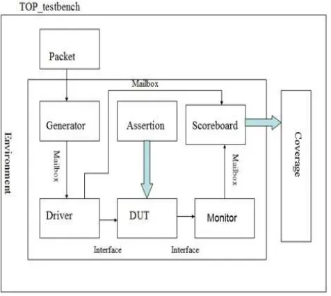
Fig -2: Verification Flow
Packet, Generator and driver are our different classes. DUT is the design under test. From the classes and DUT, we go to the monitor and scoreboard. Driver to DUT and DUT to Monitor is our Interface. Remaining arrows are the mailbox. The solid arrows signify the data that transferred between the assertions and DUT and Scoreboard to the coverage. We take inputs from the packet and scoreboard and check the coverage for the same
.
Fig -3
: Top Module Architecture Diagram4. USART INTERCONNECTION TO STM32
CONTROLLER [image:3.595.321.536.126.306.2]The Universal Synchronous Asynchronous Receiver/ Transmitter (USART) implements a synchronous and asynchronous serial bus for exchanging information. When solely asynchronous mode is supported it’s referred to as Universal Asynchronous Receiver/Transmitter (UART). Almost all microcontrollers have a serial interface (UART/USART peripheral). STM32 may be a family of 32-bit microcontroller integrated circuits by STMicroelectronics. The STM32 chips are sorted into connected series that are based mostly round the same 32-bit ARM processor core, like the Cortex-M7F, Cortex-M4F, Cortex-M3, Cortex-M0+, or Cortex-M0.Internally, each microcontroller consists of the processor core, static RAM, flash memory, debugging interface, and various peripherals.
[image:3.595.53.291.314.527.2] [image:3.595.318.560.553.745.2]© 2019, IRJET | Impact Factor value: 7.211 | ISO 9001:2008 Certified Journal
| Page 3079
The baud rate of USART measured by it connect as aperipheral to STM32f103c8.It is 32-bit ARM controller with AHB bus.
5. SIMULATION RESULTS
Fig-6: Multi master Multi slave top module
Fig-7: Transcript of loading
Fig-8: Final Transcript
5.1 Latency
The simulation result of multi master multi slave
summarized that AHB have excellent performance
latency. Compared to APB bus AHB bus use one clock
cycle for read or write operation but APB bus takes two
clock cycle for read or write transfer. To measure the
latency, in existing verification environment, monitors
and scoreboard were added, to note down the request
and grant signal along with time and number of clock
cycles were calculated by subtracting the grant time
and request time which gave us the exact arbitration
latency for each transaction.
5.2 Baud Rate
The baud rate of USART measured by it connect as a peripheral to STM32f103c8.It is 32bit ARM controller with AHB bus. USART send and receive data at a baud rate of 9600,14400,57600.
6. CONCLUSIONS
© 2019, IRJET | Impact Factor value: 7.211 | ISO 9001:2008 Certified Journal
| Page 3080
operation followed by a "First-in, first out"(FIFO) arbitrationscheme with split and wait signal. Waveform simulation take place at 100ns this is because of advantage of system verilog language. The second stage of design is Verification and functional coverage.
The output of verification transcript gives the data transfer information between monitor, scoreboard, driver, DUT, interface and top module. Finally, functional coverage checks the all possible input combination. And finally provide 100% functionally corrected output. AHB bus results excellent performance latency. The baud rate of USART peripheral using APB bus is lower than the AHB bus, because in this design USART have baud rate starting from 9600 baud/second. But APB bus have baud rate from 600 baud/second. Finally concluded that the AHB bus is better than APB bus. The performance latency and baud rate measurement result are good for AHB bus.
REFERENCES
[1] Mitic, Milica, and Mile Stojcev “A survey of three system-on-chip buses: Amba, coreconnect and wishbone,” in Proc. 41st Int. Conf. Inform. Commun. Energy Syst. Technol. (ICEST),2006.
[2] Bajaj, Preeti, and Dinesh Padole,” Arbitration schemes for multiprocessor Shared Bus”, New Trends and Developments in Automotive System Engineering, InTech, Volume 1, Issue 1, pp 610-614, May 2010. [3] Sekar, Krishna, et al, "Study of high performance AMBA
AHB Reconfigurable Arbitration for On-Chip bus architecture", in Proceedings of the 42nd annual Design Automation Conference, ACM, February 2014.
[4] Shraddha, Divekar, and Tiwari Archana, "Multichannel AMBA AHB with multiple arbitration technique", in Int. Conf. Commun. Signal Process. ICCSP, pp. 1854-1858, 2014.
[5] Murali .M, “Verification IP for AMBA AXI Protocol using System Verilog, in International Journal of Applied Engineering Research ISSN 0973-4562, Volume 12, Number 17 ,2017.