Performance Analysis of Direct-Driven PMSG
in Wind Energy Conversion System with
AC-DC-AC Converters
Y.
Mastanamma
1,
Dr. D. Subbarayudu
21
Research Scholar at Rayalaseema University, Kurnool, Andhra Pradesh and HOD-EEE/Associate Professor at Methodist College of Engineering and Technology, Abids, Hyderabad.
2
Research Supervisor at Rayalaseema University, Kurnool, Andhra Pradesh, India.
Abstract: This paper focuses on performance analysis of direct driven permanent magnet synchronous generator (DDPMSG) which are widely used in large scale wind turbines for Wind Energy Conversion Systems (WECS). The permanent magnet synchronous generator (PMSG) of 1.5 MW output power which is driven directly without gear system is analyzed. The characteristics of generator include the Wind speeds, generator speeds, active power generated, rectifier voltage. For analysis of an electrical machine, accurate prediction of the machine parameters is crucial. In real time system a permanent magnet generator is connected with wind turbine, which seems to be becoming increasing popular nowadays. The results show a proper performance of PMSG for analysis of an electrical machine in wind turbine application.
Keywords: WECS, DDPMSG, Diode Rectifier, Boost Chopper, Inverter
I. INTRODUCTION
The development of wind power in India began in the 1990s and has significantly increased in the last few years. Currently, India ranks Fifth amongst the wind energy producing countries of the world after USA, China, Germany and Spain. In 2009 -2010 India's growth rate is highest among the other top four countries.
India has an estimated potential around 49100 MW at 50 m above ground level. Strong seasonal winds blow across the Indian subcontinent during April to September. This gives enormous potential to generate Wind Energy in cost-effective manner. Central Government has conducted exhaustive wind resource assessment at more than 644 stations spread over various parts of the country. As on date 233 Wind Monitoring stations are in operation and wind studies are being conducted at a higher elevation than the earlier studies. So far, Wind farms have been installed in Andhra Pradesh, Gujarat, Karnataka, Kerala, Madhya Pradesh, Maharashtra, Rajasthan, Tamil Nadu and West Bengal. These installations were owned by public and private organizations.
Due to the increasing number of wind turbines installed, the energy production by means of wind power is increasing by approximate 30% annually [1]. Owing to high efficiency, low mechanical loss, and low maintenance cost, the direct driven wind power system including the permanent magnet synchronous generator (PMSG) is drawing people's attention more and more. Mastering the wind generating set's operation character and then improving its operation efficiency are the important issue in the research field of wind power generation. As per my research field visit Wind Power Plant at Cuddapah District ,Tirumalayapalli(Village) with Latitude of 14.540N and Longitude of 78.110E. It has Altitude of 442 meters. There are 63 units of 1.5 MW PMSG based WECS had installed in the year 2013. The total Capacity of the Wind Power Plant is 94. 5 MW and Plant Load Factor is around 30%. This Power is pumped to nearby grid. Fig. 1 shows the schematic diagram of 1.5 MW WECS at that place.
Interfacing with Grid is done with the help of AC-DC-AC conversion system. Fig 2 shows the electrical connection to grid.
Fig 2. Electrical scheme of a WECS
1) The Generator: Generator is permanent magnet excited synchronous multipole fractional slot generator directly coupled to the wind turbine rotor and designed for continuous operation. Being variable speed, the output is of Variable Voltage and Frequency and the Power Electronics is compatible to this variation as well to the grid. The Generator is copper wound with Class-F insulation and with protection class of IP23 and adequate to the designed conditions as well compatible with the interfaces. The bearing for the turbine rotor form an integral part of the generator. This comprises of Cast Main Axle, Cast Hollow Shaft with two generously dimensioned slow-speed bearings, which fulfill two functions one is they absorb the forces generated by the rotor and the other at the same time function as generator bearings.
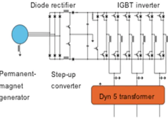
2) Power Electronic System: The PMSG is connected to Diode Bridge rectifier which converts Ac voltage of 690V (rated generator voltage) to Variable Dc voltage of 800 V-1200 V range based on wind speeds and then the Boost Converter converts this Dc voltage to a fixed DC Voltage of 1200 Volts and then Fixed DC is given to Inverter, which converts DC Voltage to Ac voltage of 620 V. Inverter is connected to Transformer. Transformer Primary is 620 V and Secondary is 33 KV. Then 33 Kv is transformed to 132 KV using another transformer which is connected to distribution lines.
Fig 2. Ac-Dc-Ac Conversion circuits
3) Power Electronics (AC-DC-AC): Fig 2. shows the AC-DC-Ac conversion circuits. The Power Electronics consists of Rectifier, Step up chopper and inverter. Rectifier is a passive type without any control. Step up chopper and inverter is controlled electronically and through software.Three parallel IGBTs are used as step up chopper to maintain a constant DC Link.Six IGBTs are used as inverter to convert the constant DC Link into 620V, 50Hz AC three phase. All these IGBTS are driven by a converter control board and PLC based Control System.All Line voltages, currents, DC Link voltages, currents, temperatures, Wind Vane, Anemometer and other sensors are interfaced to the control system through PLC based Master controller.
5) Specifications of 1.5 MW WIND Conversion System General
Wind Turbine Class GL III A
Hub Height 85 m
Type Direct Drive Horizontal Axis Wind
Turbine with variable Rotor Speed
Power Regulation Independent electromechanical pitch
system for each blade
Rated Power 1500 kW
Rotational Speed Variable, 9 - 17.3 rpm
Design Life Time 20 years
Wind Conditions
Air Density 1.225 kg / cu.m
Annual Average Wind
Speed 7.5 m/s
Wind shear 0.16
Cut-in wind speed 3 m/s
Cut-out wind speed 22 m/s
Re cut-in wind speed < 22 m/s (10 min. avg.)
Rated wind speed approx. 13 m/s
Survival wind speed 52.5 m/s
Maximum in-flow angle 8 Deg
Braking System
Primary Brake System
Aerodynamic Brake, Individual full 90 deg. blade pitch and control for each blade
Maintenance Hydraulic Brake Caliper at Generator
Rotor
Generator
Type Synchronous, Variable Speed
Cooling Passive Air Cooled
Excitation Permanent Magnet
Rated Power 1500 kW
No. of poles 88
Winding Medium Voltage, Fractional Slot
Rated Voltage 690 V
Frequency Variable
No. of phases 6
Insulation Class F
Protection Class IP 23
Generator Protection 2 x Circuit Breaker Switches at
6) Observations taken and Analysis: At wind power plant observations were taken for one day for every 10 minutes i.e., on 01/05/2019.Graphs given below obtained from data collected.The following graphs are self explanatory.
0 200 400 600 800 1000 1200
1 12 23 34 54 56 67 78 89
10 0 11 1 12 2 13 3 14 4 A ct ive P o we r an d W in d S p ee d Time stamps
Active Power and Wind Speed
active_power_avg(KW) wind_speed_avg 0 5 10 15 20
1 10 19 28 37 64 55 64 73 82 91
1 0 0 1 0 9 1 1 8 1 2 7 1 3 6 W in d S p e ed a n d G en er at o r Sp ee d Time Stamps
Wind Speed and Generator Speed
with Time stamps
wind_speed_avg generator_speed_avg
0 500 1000 1500
1 11 21 31 41 51 61 71 81 91
1 0 1 1 1 1 1 2 1 1 3 1 1 4 1 R e ct if ie r V o lt ag e, A ct ive P o we r an d W in d S p ee d Time stamps
Rectifier Voltage ,Active Power
and Wind Speed
rectifier_voltage_avg active_power_avg(KW)
It was observed that with variations in wind speeds from 3 to 10 m/s on that day the power generated also changing as shown in graph. At the same time there are corresponding variations in Genertor Speed and rectifier voltage.The efficiency of the system is much better than Induction generator based WECS.
I sincerely thank the management and Staff of Hetero Wind Power Plant for permitting me to visit and for the explanation of every part in the 1.5 MW WECS. It helped me to carryout my simulations with good understanding of the system.
REFERENCES
[1] T. Ackermann, Wind power in power systems. John Wiley, Ltd, 2005.
[2] Thongam, J.S. Bouchard and P. Ezzaidi, “Wind Speed Sensorless Maximum Power Point Tracking Control of Variable Speed Wind Energy Conversion
Systems,” IEEE International Electric Machines and Drives Conference.pp. 1832 – 1837, May 2009
[3] Shuhui Li, Timothy A.Haskew and Ling Xu, “Conventional and noel control designs for direct driven PMSG wind turbines,” Electric Power Systems
Research., pp.328–338, June. 2009.
[4] Yan Gangui, Wei Zhicheng, Huang he, “Optimal power control of directly-driven permanent magnet synchronous generator wind turbine,” Elcctric machines
and control, vol. 13, pp. 56-61, nov 2009.
[5] M. Liserre, R. Cardenas, M. Molinas, and J. Rodriguez, “Overview of multi-MW wind turbines and wind parks,” IEEE Trans. Ind. Electron., vol. 58,no. 4, pp.