Comparative Study of RC Building with and
without Vertical Irregularity Subjected to
Earthquake and Wind Loading
Dr. A. R. Gupta 1, Vicky P. Dhawale2 1
Guide & M.E Coordinator, Department of Structural Engineering C.O.E.T. Akola, S.G.B.A.U. Amravati (India)
2
PG Student, Department of Structural Engineering C.O.E.T. Akola, S.G.B.A.U. Amravati (India)
Abstract: Vertical irregular structures constitute a large portion of the modern urban infrastructure. The group of people involved in constructing the building facilities, including owner, architect, structural engineer, contractor and local authorities, contribute to the overall planning, selection of structural system, and to its configuration. This may lead to building structures with irregular distributions in their mass, stiffness and strength along the height of building. When such structures are located in a high wind zone and seismic zone, the safety of the structure becomes more challenging. So to acquire safety against additional deformations there is need to study of detailed considerations to design earthquake resistance structures as well as wind resistance structure. The work done over here is to find out the effect of vertical irregularity for the structure subjected to seismic and wind loads. Further the comparison is done for various models analyzed and on basis of observation remark are drawn. While considering the effect of seismic or wind force on high rise structure, study reveals that the effect of seismic forces are more vulnerable in terms of Displacement , Drift values , Member end forces and Moments developed.
Keywords: Irregular Structure, Wind Analysis, Seismic Analysis, Vertical Irregularity, High Rise Building, etc.
I. INTRODUCTION
From last few decades, The number of tall structures and skyscrapers around the world has increased drastically which is serving many purpose like residential, offices etc. and many other commercial requirements. Beautiful aesthetic appearance and eye catching shapes and projections of the structures has increased the demand of tall structure. In the perspective of structural engineer designing such eye catching shapes and the projections in a high rise structures is a challenging job to study the behaviour of structure. In vertically irregular structure, failure of structure starts at a point of weakness. This weakness arises due to discontinuity in mass, stiffness and geometry of structure. The structures having this discontinuity are termed as Irregular Structure. So, The effect of vertical irregularities in the seismic and the wind load performance of a structure becomes really important. Height wise changes in stiffness and mass render the dynamic characteristics of these buildings different from regular building.
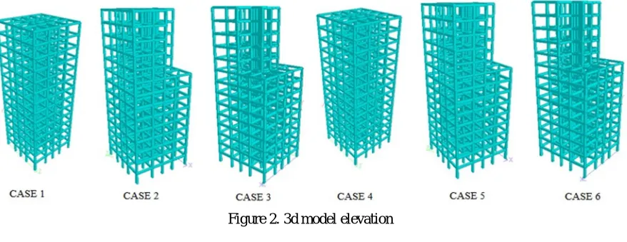
[image:1.612.157.426.513.700.2]Figure 2. 3d model elevation
II. MODELLING AND ANALYSIS
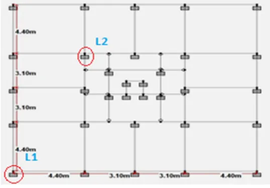
The study in this thesis is based on an investigation on effect of vertical irregularity in high rise structure subjected to wind and seismic forces. In this thesis total six models are analyzed. All the models with and without vertical irregularity are analyzed by static analysis method in STAAD. Pro software. All the selected buildings are designed as per Indian Standards. The STAAD. Pro Software is used to develop 3D model and to carry out analysis. The seismic loads and wind loads to be applied on the structure are based on Indian Standards. The analysis is performed for seismic zone IV and basic wind speed 47 m/s as per IS 1893(Part 1) : 2002 and IS 875(Part 3) : 1987. A thirteen storey reinforced concrete structure with and without vertical irregularity is analyzed with seismic and wind forces. To study the effect of seismic forces and wind forces with vertical irregularity, six cases are modelled and analyzed in which Case 1, Case 2 and Case3 are subjected to seismic forces and Case 4, Case 5 and Case 6 are subjected to wind forces for the same location. Case 1 and Case 4 are the structures with no vertical irregularity and maintained symmetry. Case 2 and
Case 5 are the structures with removed quarter portion above 8th storey and case 3 and Case 6 are structures with removed half
portion above 8th storey.
Definition for L1 and L2 :
L1 – First location for the comparison of result data. L2 – Second location for the comparison of result data.
TABLE 1
specifications of plan
Total Area 225 sq. m
Plan 15 x 15 Sq. m
Structure Height 39 m (3 m each storey)
Bays 4 bays in X and Z direction.
Support Type Fixed Support
Column a. column
0.6 x 0.38 m (From GF to 8th floor)
b. column 0.45 x 0.38 m (From 9thto 13th floor)
c. column 0.38 x 0.30 m (Lift column)
Beam
a. Beam 0.6 x 0.30 m (GF to 8th floor)
b. Beam 0.45 x 0.30 m (9th to 13th floor) c. Beam
0.45 x 0.30 m ( All secondary beams)
d. Beam 0.38 x 0.30 m (Lift beam)
TABLE 2 structural data
Type of structure OMRF
No. of stories G+12
Storey height 3m
Grade of concrete M25
Grade of steel Fe 415
Thickness of slab 150mm
Seismic zone IV
Location Delhi
Wind speed 47 m/s
[image:2.612.335.545.474.642.2]III. RESULT AND DISCUSSION
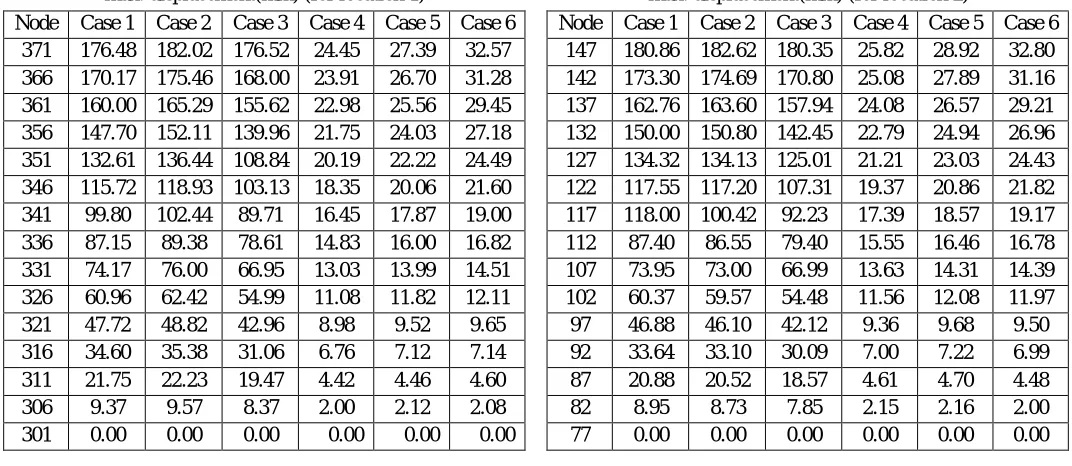
[image:3.612.38.574.163.396.2]From the values of Table 3, Table 4, Table 5, Table 6, Table 7, Table 8, Table 9 and Table 10 when the comparison is made for all the 6 cases, it can be observed that the values are more for the structure subjected to seismic forces as compared to the structure subjected to wind forces.
TABLE 3 TABLE 4
max. displacement(mm) (for location 1) max. displacement(mm) (for location 2)
Node Case 1 Case 2 Case 3 Case 4 Case 5 Case 6 Node Case 1 Case 2 Case 3 Case 4 Case 5 Case 6
371 176.48 182.02 176.52 24.45 27.39 32.57 147 180.86 182.62 180.35 25.82 28.92 32.80
366 170.17 175.46 168.00 23.91 26.70 31.28 142 173.30 174.69 170.80 25.08 27.89 31.16
361 160.00 165.29 155.62 22.98 25.56 29.45 137 162.76 163.60 157.94 24.08 26.57 29.21
356 147.70 152.11 139.96 21.75 24.03 27.18 132 150.00 150.80 142.45 22.79 24.94 26.96
351 132.61 136.44 108.84 20.19 22.22 24.49 127 134.32 134.13 125.01 21.21 23.03 24.43
346 115.72 118.93 103.13 18.35 20.06 21.60 122 117.55 117.20 107.31 19.37 20.86 21.82
341 99.80 102.44 89.71 16.45 17.87 19.00 117 118.00 100.42 92.23 17.39 18.57 19.17
336 87.15 89.38 78.61 14.83 16.00 16.82 112 87.40 86.55 79.40 15.55 16.46 16.78
331 74.17 76.00 66.95 13.03 13.99 14.51 107 73.95 73.00 66.99 13.63 14.31 14.39
326 60.96 62.42 54.99 11.08 11.82 12.11 102 60.37 59.57 54.48 11.56 12.08 11.97
321 47.72 48.82 42.96 8.98 9.52 9.65 97 46.88 46.10 42.12 9.36 9.68 9.50
316 34.60 35.38 31.06 6.76 7.12 7.14 92 33.64 33.10 30.09 7.00 7.22 6.99
311 21.75 22.23 19.47 4.42 4.46 4.60 87 20.88 20.52 18.57 4.61 4.70 4.48
306 9.37 9.57 8.37 2.00 2.12 2.08 82 8.95 8.73 7.85 2.15 2.16 2.00
[image:3.612.39.574.433.722.2]301 0.00 0.00 0.00 0.00 0.00 0.00 77 0.00 0.00 0.00 0.00 0.00 0.00
TABLE 5 TABLE 6
beam end forces (for location 1) beam end forces (for location 2)
Node Max.Shear Force(KN) Node Max.Shear Force(KN)
Case 1 Case 2 Case 3 Case 4 Case 5 Case 6 Case 1 Case 2 Case 3 Case 4 Case 5 Case 6
371 39.08 39.56 41.16 24.04 24.28 24.62 147 54.17 53.00 24.29 35.77 35.01 13.54
366 43.15 90.77 94.51 -1.97 27.17 55.57 142 109.29 105.75 63.20 73.60 71.26 31.98
361 93.52 146.30 152.31 1.83 57.70 88.56 137 168.70 164.00 110.55 113.10 109.20 51.11
356 147.95 205.49 214.25 1.64 88.47 118.03 132 231.70 225.20 164.52 152.90 147.63 70.93
351 206.02 209.56 218.33 1.62 119.62 149.70 127 297.68 229.30 223.50 193.20 186.40 91.07
346 266.96 271.44 282.40 1.49 151.03 181.34 122 364.99 293.20 292.70 234.20 226.30 133.80
341 329.43 334.54 343.61 4.58 182.63 218.72 117 416.62 358.90 333.40 273.90 264.80 170.50
336 406.97 412.45 415.98 1.58 220.89 257.36 112 473.30 410.60 381.80 312.02 301.50 209.41
331 484.95 490.43 490.02 1.63 293.70 295.29 107 537.23 465.40 435.60 351.50 339.70 249.60
326 562.66 567.79 564.08 1.63 330.79 332.27 102 604.18 524.48 493.60 392.50 379.60 291.30
321 639.69 644.17 637.61 1.62 367.17 368.44 97 674.19 586.32 555.70 435.50 421.90 334.65
316 715.57 719.13 710.02 1.56 402.57 403.55 92 747.67 651.30 622.04 480.90 466.50 379.91
311 789.84 792.23 780.83 1.39 436.83 437.45 87 825.09 792.27 693.00 528.66 513.70 427.40
306 862.03 863.07 849.54 -2.25 469.34 469.56 82 905.90 871.60 768.70 579.50 564.36 478.16
TABLE 7 TABLE 8
beam end forces (for location 1) beam end forces (for location 2)
Node Bending Moment (KN.m) Node Bending Moment (KN.m)
Case 1 Case 2 Case 3 Case 4 Case 5 Case 6 Case 1 Case 2 Case 3 Case 4 Case 5 Case 6
371 977 1002 1005 445 454 446 147 -960 -1011 720 -190 -200 182
366 -554 1003 1013 606 -318 291 142 -1201 -1276 950 -156 -183 172
361 -725 1199 1211 616 -297 325 137 -1538 -1640 1162 -202 -247 204
356 -929 1327 1343 642 -317 333 132 -1791 -1905 1289 -232 -290 223
351 -1101 -1142 -1154 664 -331 346 127 -1986 1802 1455 -265 -324 232
346 -1290 -1340 -1356 684 -348 348 122 -1976 2046 -1642 -270 -222 -256
341 -1775 -1851 -1874 990 -416 595 117 -2350 1784 -2049 -334 -273 -277
336 -1783 -1852 -1872 1033 -535 515 112 -2573 2219 -2201 -391 -363 -338
331 -1786 -1859 -1885 1012 534 512 107 -2639 2274 -2288 -420 -409 -376
326 -1793 -1868 -1902 993 522 502 102 -2663 2382 -2325 -450 -448 -414
321 -1787 -1862 -1904 969 505 488 97 -2651 2451 -2328 -477 -484 -448
316 -1763 -1838 -1887 936 483 469 92 -2062 2483 -2292 -498 -513 -477
311 -1736 -1809 -1866 889 448 436 87 -2515 -2265 -2220 -515 -528 -499
306 -1781 -1858 -1926 778 327 320 82 -2055 -1571 -1811 -423 -386 -414
301 -2794 -2933 -3067 0 0 0 77 2504 2601 2217 0 0 0
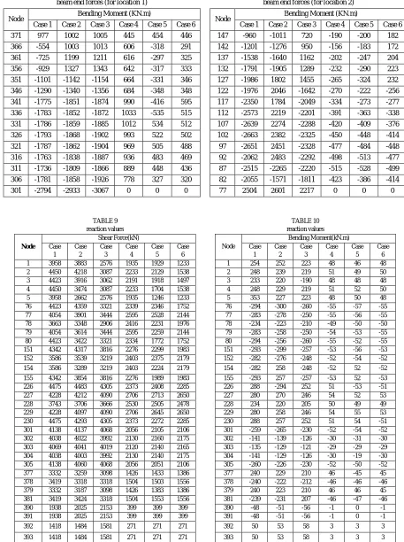
TABLE 9 TABLE 10 reaction values reaction values
[image:4.612.74.531.105.717.2]IV. CONCLUSION
When the comparison is done for Nodal displacement values, Beam end forces and Reaction values between structure subjected to seismic forces and wind forces with and without vertical irregularities, the values are more for the structure subjected to seismic forces. As per the clause of IS 1893 (Part 1):2002 either one of the force should be considered i.e. seismic or wind. From the above study it can be concluded that even if the structure is having vertical irregularity the analysis and design considering seismic forces will make structure safe against wind load also.
REFERENCES
[1] G. Guruprasad, G. Srikanth (2017), "Seismic Evaluation of Irregular Structures", International Journal of Research in Advanced Engineering Technologies, Vol. 6, Issue 2, pp 26-35.
[2] Piyush Mandloi, Prof. Rajesh Chaturvedi (2017), "Seismic Analysis of vertical Irregular Building with Time History Analysis", IOSR Journal of Mechanical and Civil Engineering, Vol. 14, Issue 4 Ver. 3, pp 11-18.
[3] Nonika. N, Mrs. Gargi Danda De (2015), "Comparative Studies on Seismic Analysis of Regular and Vertical Irregular Multistoried Building", International Journal for Research in Applied Science and Engineering Technology, Vol. 3, Issue VII, pp 396-407.
[4] Albert Philip, Dr. S. Elavenil (2017), "Seismic Analysis of High Rise Buildings with Plan Irregularity", International Journal of Civil Engineering and Technology, Vol. 8, Issue 4, pp 1365-1375.
[5] Kusuma B. (2017), "Seismic Analysis of A High Rise RC Framed Structure with Irregularities", International Research Journal of Engineering and Technology, Vol. 4, Issue 7, pp 1338-1342.
[6] Aniket A. kale, S. A. Rasal (2017), "Wind and Seismic Analysis of Multistory Building", International Journal of Emerging Research In Management and Technology, Vol.6, Issue 5, pp 25-30.
[7] Shaikh Muffassir, L. G. Kalurkar (2016), “Study of Wind Analysis of Multistory Composite Structure For Plan Irregularity”, International Journal of Advanced Technology In Engineering And Science, Vol.04, Issue 09, pp 36-45.
[8] A. A. Kale, S. A. Rasal (2015), “Seismic And Wind Analysis of Multistorey Building : A Review”, International Journal of Science and Research, pp 1894-1896.
[9] SanhikKarMajumder, Prof. Priyabrata Guha (2014), “Comparison Between Wind and Seismic Load On Different Types of Structures”, International Journal of Engineering Science Invention, Vol. 3, Issue 4, pp 41-54
[10] IS 456 : 2000 : Plain and reinforced concrete code of practice.
[11] IS 1893 (Part 1) - 2002 : Criteria for earthquake resistant design of structures.