Available from Sheffield Hallam University Research Archive (SHURA) at:
http://shura.shu.ac.uk/24394/
This document is the author deposited version. You are advised to consult the
publisher's version if you wish to cite from it.
Published version
ISSA, Walid, SHARKH, Sulieman and ABUSARA, Mohammad (2019). Hybrid
Generators-based AC Microgrid Performance Assessment in Island Mode. IET
Power Electronics.
Copyright and re-use policy
1
Hybrid Generators-based AC Microgrid Performance
Assessment in Island Mode
Walid Issa
1*,
Suleiman Sharkh 2,
Mohammad Abusara 31 Electrical Engineering Department, Sheffield Hallam University, Pond Street S1 1WB, Sheffield, UK
2 Electro-Mechanical Engineering Research Group, University of Southampton, Southampton, SO17 1BJ, UK
3 Renewable Energy Research Group, University of Exeter, Penryn, TR10 9EF, UK
Abstract – Achieving an accurate steady-state averaged active power sharing between parallel inverters in islanded AC microgrids could be realized by a traditional droop control. For identical inverters having the same droop gains, it is assumed that the transient average power responses will be similar, and no circulating current will flow between the units. However, different line impedances could influence the instantaneous power significantly and thus circulating power flows among the inverters particularly during sudden disturbances such as load changes. This power, if absorbed by an inverter, will lead the DC link voltage to rise abruptly and trip the inverter, thus, degrading the performance of the whole microgrid. The problem becomes worse when hybrid generators are serving as unidirectional power source. This paper assesses the performance of hybrid generators within an islanded microgrid against the mismatch in line impedances. Two schemes to stabilize the microgrid are proposed. In addition, a participation factor analysis is developed to select the most effective controller scheme to bound the DC link voltage and minimize the circulating power. Simulation and experimental results are presented to verify the analysis and the capability of the proposed controller.
1. Introduction
A microgrid is an energy system composed of loads and distributed energy resources (DER) such as distributed generators (DG) and energy storage systems (ESS) that can operate either in island or grid-connected configuration [1]. Power electronic inverters are used to integrate energy sources such as PV, wind, batteries to form an AC microgrid. Parallel operation improves redundancy, which further improves reliability.
Power sharing between parallel inverters using droop control has been extensively used and reported in the literature because it is easy, simple and inherently responsive when connected in parallel with synchronous generators [2]-[4]. In addition, it only uses local measurements without the need for high speed communications. To maintain good stability margins for the system, the droop control loops have to be designed with lower bandwidth than that of the inner voltage and current regulation loops. This requires using small droop gains and/or using slow power measurement low pass filters [5]-[6]. Droop gains are chosen to give satisfactory transient power response and acceptable steady state deviation in voltage and frequency. It is capable of achieving accurate steady state averaged active power sharing between parallel inverters despite of any mismatch in the inverter’s output impedances and line impedances. However, it does not guarantee equitable sharing of transient power. Large mismatch in line impedance results in large differences in transient power circulation between the inverters. This energy can be absorbed by a DC/DC converter if the energy source is a battery, for example, to maintain a regulated DC link voltage. However, in case of unidirectional source as fuel cell or micro-gas turbine, the circulating power can’t be absorbed or ceased causing unstable DC link response [7].
Many controllers have been proposed in the literature to improve the averaged transient power responses of paralleled
inverters. Guerrero et al. [8] introduced power
derivative-integral terms into the conventional droop control to improve the dynamic response and to minimize the circulating
currents between the paralleled inverters. Avelar et al. [6]
proposed an extra phase loop to mitigate the transient response peak and to avoid overrating the unit. In [9], a supplementary loop was proposed around the conventional droop control to stabilize the system while using high power angle droop gains. Other auxiliary loops were presented in [10] and [11] with the droop controller to increase the system’s damping.
Adaptive droop controllers were also proposed in [12] and [13] to improve the control performance and to provide seamless mode transfer. In [14], an adaptive derivative term was added to the droop controller to decrease current overshoot and improve stability. Piecewise linear droop control was presented in [15] and gain-scheduled decoupling control strategies were proposed in [16]. In [17], a central controller with low bandwidth communication is employed in order to tune the droop parameters properly under different load conditions.
Although the abovementioned studies have focused on improving the transient dynamics of average power control, none has addressed the instantaneous transient power impact on the stability of the parallel inverters. Furthermore, none of these studies considered the effect of mismatched line impedances on microgrid system damping and circulated energy. In our previous study [7], we investigated the impact of circulating power on DC link voltage under unintentional islanding case and a controller was proposed to stabilize the DC link voltage. The findings approved the significance of such studies in improving the operational reliability of the microgrids.
2
such as to reduce voltage fluctuation due to switching current. For the commercial inverters reported in [18], the inverters have a switching frequency of 8kH, DC link capacitor of 2mF and are rated at 60kW. The same DC link capacitor value was used in [7] and it was shown that it was not adequate to prevent the rise in DC link during unintentional islanding. The controller presented in this paper will allow to control the DC link voltage in case of sudden change in the load without the need to increase DC link capacitance.
This paper investigates the impact of mismatched line impedances on the performance of parallel inverters supplied by different energy sources and assesses the instantaneous circulating power responses against the stability of the microgrid. A small signal state space model of a microgrid consisting of three inverters is used to analyse the system. Two controller schemes based on supplementary phase and frequency loops are proposed to maintain the microgrid stability. A participation factor assessment is used to select the most effective controller scheme with the least action to bound the DC link voltage. The proposed controller has been validated by simulation and experimentally.
- -Bat PWM * dc V dc C v k c k v sL * V l
i vc
1
L L2
C Converter controller DC L / DC DC Converter /
DC A C Inverter c PI v PI -dc i dc v PWM - -v k c k v sL * V l
i vc
1
L L2
C /
DC A C Inverter
Droop &Voltage controller
PWM dc C Droop controller Droop controller - -dc C v k c k v sL * V l
i vc
1
L L2
C /
DC A C Inverter PWM Droop controller o i o i o i Fuel Cell Micro-Gas turbine Load A C B u s 1 Line L 2 Line L PWM * dc V dc C Converter controller DC L c PI v PI -dc i dc v / AC DC Rectifier / DC DC Converter PWM * dc V Converter controller DC L / DC DC Converter c PI v PI -dc i dc v
Droop &Voltage controller
Droop &Voltage controller
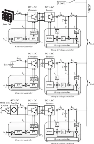
Fig. 1 Microgrid structure under study
[image:3.595.115.277.327.575.2]2. System Overview
Fig. 1 shows a microgrid system composed of three DG units supplied by different energy sources. Each DG unit has a DC/DC converter and a DC/AC inverter with a DC link capacitor in between. For a battery-based energy source, the DC link voltage is regulated by a bidirectional buck/boost DC/DC converter [19]. For fuel cells and gas micro turbine -based systems unidirectional boost DC/DC converters are used. Typically, in such a system, the gas turbine is taking the role of controlling the AC bus voltage and frequency. However, in our system, it will work as an auxiliary supply and the battery-based system will fulfill the bus control
requirements. This supports the carbone emission reduction
plans. Furthermore, the battery system can generate and absorb power to and from the AC bus to balance the power flow by the droop control while the auxiliary supply can only generate power. This might be advantageous when the generation is more than the load which gives the chance inherently to charge the battery if possible [20]. Also it is worth mentioning that the DC link voltage of the fuel cell-based unit could be controlled by the inverter side controller or by the DC converter controller [21]-[23]. To maintain the consistency and to simplify the modelling, the DC converter is chosen to regulate the DC link voltage knowing that this might degrade the power efficiency.
Normally, there is no control link between the DC/DC converters and DC/AC inverters. The DC/DC converters regulate the DC link voltage against any disturbances caused by the inverter side. The inverters manage the output power and voltage to satisfy the load demand. In the next sections, the study highlights cases where the DC link voltage can’t be controlled because of this isolation between the controllers of the two converters.
In cascaded control systems, and as a rule of thumb, the inner voltage loop must have a bandwidth that is 3-5 times higher than that of the outer power loop to preserve the stability and tracking resolution [14]. The modelling of a microgrid adopting the droop controller is well-established in the literature [7]-[26]. The inner voltage loop is normally neglected in the modelling because its response time is much faster than the outer droop control loop. In addition, the droop control is developed based on the steady-state analysis of power flow. As a result, the dynamics of the power control loop shall be sufficiently slower than the DG voltage tracking dynamics [3]. Therefore, each inverter can be modelled by its Thevenin equivalent circuit as shown in Fig. 2. The equivalent circuit model consists of an ideal voltage
source, 𝑉𝑜, and an output impedance; 𝑅𝑜+ 𝑗𝜔𝐿𝑜; which can
be calculated as in [27] and [28]. The voltage source will be controlled directly by the droop equations.
o
R Lo
o I Output Impedance o V o I Power Control o o
V
PCC
PCC
V
Fig. 2 Thevenin equivalent model of an inverter
-p
m
0 HP( )s
1 s c c s + P ins p PCC
o -1 s PCC Fig. 3 Small signal model of the droop controller for one inverter
[image:3.595.317.483.483.652.2]3
the voltage magnitude. Other load models like constant current and constant power loads can be studied in future works if needed. However, the problem happens in low load, ideally zero, cases as will be explained in the next section. Thus, the type of load is expected to have an insignificant impact on the considered problem.
3. Droop Control Operation
The frequency and voltage droops are described by (1) and (2), respectively as:
o
m P
p
= −
, (1)o q
V V n Q
= −
, (2)where 𝜔𝑜, 𝑉𝑜 , 𝑚𝑝, and 𝑛𝑞 are the nominal frequency,
nominal voltage, frequency droop coefficient, and voltage
droop coefficient, respectively. P and Q are the average
measured output active and reactive powers, respectively.
Average power is obtained from the instantaneous power pins
using a low pass filter as,
c ins c
P p
s
=
+ , (3)
where 𝜔𝑐 is the cut-off frequency which is chosen to be much
lower than the fundamental frequency to provide good filtration and frequency independence of the dynamics of the inner loops. From Fig. 2, the instantaneous output active power is related to the power angle and given by
sin( )
o PCC o PCC
ins
o V V p
X
−
= , (4)
where 𝑉𝑜 𝑎𝑛𝑑 𝑉𝑃𝐶𝐶 are the output voltages, 𝛿𝑜 𝑎𝑛𝑑 𝛿𝑃𝐶𝐶 are
the phase angles of the inverter and PCC nodes, respectively.
𝑋𝑜 is the equivalent output reactance of the inverter where 𝑅𝑜
is neglected. By perturbing (1) we get
P
m P
= − . (5)
By perturbing (4) and assuming constant Vo, VPCC we get,
ins P
p H
= , (6)
where o PCCcos( eq)
P
o V V H
X
= , = − o PCC, eqis the
equilibrium point of the phase difference around which the perturbation is performed. From (3), (5) and (6), the small signal model of the droop control loop can be represented by the block diagram of Fig. 3. By ignoring the LPF in Fig. 3,
the transfer function that relates the output power P to the bus
frequency PCCis given by
p PCC
p p
H P
s m H
−
=
+ (7)
Two observations can be made from (7). First, the DC gain
equals −1 𝑚⁄ 𝑝 which means that if the inverters have the
same 𝑚𝑝, they will all achieve equal steady state active power
sharing. However, the transient response is determined by the
pole −𝑚𝑝𝐻𝑝 which depends on both values of 𝑚𝑝 and 𝐻𝑝.
Consequently, equal 𝑚𝑝 gains will not guarantee equal
transient power sharing between the inverters unless all 𝐻𝑝
are equal, i.e, 𝑋𝑜 are equal. The corresponding transient
instantaneous power, if negative, causes a rise in the DC link voltage. The second observation is that the dynamic response
of the droop controller is significantly affected by 𝑋𝑜, which
is determined by the inverter’s output impedance and the line impedance between the inverter and the PCC. Thus, each inverter might have different damping depending on its
location within the microgrid. It is important to take this into
account when determining the droop gain 𝑚𝑝, which is
normally chosen to satisfy the steady state condition such as
max min max
p m
P
−
, (8)
where 𝜔𝑚𝑎𝑥 𝑎𝑛𝑑 𝜔𝑚𝑖𝑛are the maximum and minimum
allowable values of frequency and 𝑃𝑚𝑎𝑥 is the maximum
output average active power of the inverter.
In Fig. 3, the frequency at the PCC, ∆𝜔𝑃𝐶𝐶, is represented as
a disturbance to the droop controller, which is mainly determined by the load. It is important to study the effect of varying loads on the transient power and hence on the stability of the DC link voltage. Unfortunately, the small signal model in Fig. 3 cannot be used for this study because a whole microgrid model needs to be developed in order to
determine ∆𝜔𝑃𝐶𝐶. A state space small signal model was
developed by the authors in a previous work will be used for this study in the next sections.
4. Dynamic Analysis
The microgrid model developed in [24] will be used in this paper to assess the microgrid stability when the load changes abruptly with the existence of significant line impedance mismatch. The model was verified by detailed simulation results and also by experimental results in [25]. The model was established in the rotating DQ frame including the dynamics of the power loops, network, and loads. The state space model has the form of
x Ax
=
. .
. . . . . .
dc od oq oq
FC Batery
T
oq LineD LineQ LoadD LoadQ
Distribution lines Loads
GT
x P Q v i i i
i i i i i
=
(9)
where 𝐴 is the state space matrix.
As was shown in (7), the line impedance alters the locations of the designed eigenvalues and hence the damping. Fig. 4a shows the dominant eigenvalues of the microgrid when the
three inverters have 1𝑚𝐻 output inductance with negligible
line impedances (see Fig. ) and 𝑚𝑝 varies from 5 × 10⁻⁵ to
5 × 10⁻³. The eigenvalues traces are identical and the
inverters will behave similarly. Fig. 4b shows the same traces
but with different line inductances: 𝐿𝐿𝑖𝑛𝑒1=
1𝑚𝐻 𝑎𝑛𝑑 𝐿𝐿𝑖𝑛𝑒1= 2𝑚𝐻. It is clear that for the same 𝑚𝑝
range, the corresponding eigenvalues represent different damping ratios and the poles are shifted from their original locations. This might increase oscillation and overshoot
highly. The eigenvalues when 𝑚𝑝= 3 × 10⁻³ are
highlighted in both figures to show that the same droop gain produces different damping ratios of the output power
responses. Increasing 𝑚𝑝 is desirable for achieving high
sharing accuracy but it degrades the stability.
4
[image:5.595.304.498.118.181.2]higher values which can trip the system. With the parameters in Table 1 and with the droop gains selected according to (8), a microgrid model was built in Matlab/Simulink. The active power responses and the corresponding DC link voltages are obtained when the load changed suddenly from 100% to 0%. Fig. 5 shows the responses when identical distribution lines
are used, 𝐿𝐿𝑖𝑛𝑒1,2= 0. The responses are quite identical and
the DC link voltages are only slightly affected. In Fig. 6, the power responses are differently damped and some power is imported. If the DC/DC converter is bi-directional as for the battery systems, it will sink the power from the DC link capacitor. However, if the DC/DC converter is unidirectional as in the systems of fuel cell and gas micro-turbines, the DC voltage can’t be bounded as shown in Fig. 6b.
3
at mP 3 10
−
=
3
at mP 3 10
−
=
(a) (b)
Fig. 4 Dominant system eigenvalues when 0.5 × 10⁻⁴>
𝑚𝑝> 5 × 10⁻³ and lines inductances are (a) neglected (b)
𝐿𝐿𝑖𝑛𝑒1= 1𝑚𝐻 𝑎𝑛𝑑 𝐿𝐿𝑖𝑛𝑒1= 2𝑚𝐻
Full Load
Zero Load
Fuel-Cell module Gas micro-turbine module
Battery module
Battery module
Gas micro-turbine module Fuel-Cell module
(a) (b)
Fig. 5. Detailed simulation results of inverter’s power and
DC link voltage responses under load change when identical distribution lines are used
(a) (b)
Trip Level Full Load
Zero Load
Battery module Gas micro-turbine module Fuel-Cell module
Fuel-Cell module Gas micro-turbine module
Battery module
Fig. 6 Detailed simulation results of inverter’s power and DC link voltage responses under load change when different
distribution lines are used
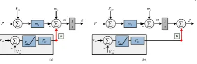
5. Supplementary Phase Loop Controller
To guarantee stable state responses within a microgrid during the normal operation, Fig. 7 shows two proposed control strategies. Once the DC link voltage exceeds a triggering
value, 𝑣𝑡𝑟, a supplementary loop is activated. This loop will
affect either (a) the frequency or (b) the phase states. In this paper an investigation is carried out to choose the state which has the major influence on the DC link voltage state. This will lead to minimizing the controller effort needed to limit the DC link voltage and thus using a small controller gain, which preserves the stability margins.
- * dc V dc P dc v P ref P -p m -o 1 s tr v a - * dc V dc P dc v P ref P -p m -o 1 s tr v b (a) (b)
Fig. 7 Proposed controller schemes (a) frequency loop (b) phase loop
By analysing the first control track, (a), where the controller output signal manipulates the frequency state, the small signal output frequency from (1) is derived as:
p dc dc
m P P v
= − + , (10)
where △ 𝑣𝑑𝑐 is a small signal state of the DC link voltage and
derived in [7] as:
dc
dc ins
k
v p
s
= − (11)
where 𝑘𝑑𝑐 is the DC voltage linearizing factor and the
negative sign denotes a power negative flow.
By ignoring the power measurement LPF and assuming that the average and instantaneous powers are equal and by substituting (11) in (10) we get
( dc dc)
p
P k
m P
s
= − + (12)
Therefore, the phase state is obtained as:
2
p dc dc
m s P k
P s
+
= −
(13)
Similarly, for the control track (b), the frequency and phase states are derived as:
(m s P kp dc dc) P
= − + (14)
p dc dc
m s P k
P s
+
= −
(15)
Table 1 Simulated system parameter
Symbol Description Value
𝐿𝑜,𝑖, 𝑅𝑜,𝑖 Inverter output impedance 1 mH, 0.1Ω
𝐿𝐿𝑖𝑛𝑒,1, 𝑅𝐿𝑖𝑛𝑒,1 Line 1 impedances 1 mH, 0.002Ω
𝐿𝐿𝑖𝑛𝑒,2, 𝑅𝐿𝑖𝑛𝑒,2 Line 2 impedances 2 mH, 0.0035Ω
𝑚𝑝 Frequency drooping gain 1 × 10⁻³ rad/s/W 𝑛𝑞 Voltage drooping gain 1 × 10⁻³ V/Var
𝑉𝑜 Voltage set point 110 Vrms
𝑓𝑜 Frequency set point 50 Hz
𝜔𝑐 Measurement filter cut-off frequency 30 rad/sec
𝑉𝐷𝐶𝑙𝑖𝑛𝑘∗ Nominal DC link voltage 200 V 𝑉𝑡𝑟𝑖𝑝 DC link trip voltage 280 V 𝑣𝑡𝑟 Triggering voltage level 215 V
𝑘𝑑𝑐 Linearization factor relating 𝑉𝐷𝐶𝑙𝑖𝑛𝑘2 to 𝑉𝐷𝐶𝑙𝑖𝑛𝑘
2.5
𝐶𝑑𝑐𝑙𝑖𝑛𝑘 DC link capacitor for ESS, µGT and
PV
2000𝜇𝐹
𝑃𝑑𝑐 Proposed controller gain 0.5 × 10⁻³
Comparing equations (12) and (14) reveals that method (a) acts as a PI controller for the output power. This might not provide fast action against the imported power. On the other hand, method (b) acts as a PD controller. Here, the power derivative has not been implemented directly but its action has been realized by the proposed loop. It is well-known that the derivative term introduces faster response which is required to limit the imported power and the DC link voltage rise. Furthermore, compared to (15), the additional pole at the
[image:5.595.100.497.142.611.2] [image:5.595.107.287.256.328.2]5
margins. Based on the above discussion, method (b) is expected to perform better.
6. Participation Factor Analysis
To provide more insight into the superiority of method (b) over method (a), a participation analysis has been carried out
[29]. The participation factor, 𝑝𝑘𝑖 in (16), of states on an
eigenvalue is a measure of the influence of the states on that
eigenvalue. In contrast, the participation factor, 𝜋𝑘𝑖 in (17),
of eigenvalues on a state is a measure of which mode mostly form the state’s response.
ki ki ik
p =r l , (16)
2
(Re{ }) Re{ }(Re{ })
ki
ki T
ki ki
l
l l
= , (17)
where 𝑘 denotes the 𝑘𝑡ℎ state, 𝑖 denotes the 𝑖𝑡ℎ mode 𝑙 and 𝑟
denote the left and right eigenvectors.
The system eigenvalues are calculated from (9) as in Table 2 where the dominant eigenvalues are bolded.
Table 2 Microgrid system eigenvalues
Eigenvalue Location Eigenvalue Location
𝛌𝟏 0 λ14 -148+316i
𝛌𝟐 0 λ15 -148-316i
𝛌𝟑 0 λ16 -83 +314i
𝛌𝟒 -2147483648+314i λ17 -83-314i
𝛌𝟓 -2147483648-314i λ18 -5
𝛌𝟔 -2147483648+314i λ19 -7
𝛌𝟕 -2147483648-314i λ20 -19+6i
𝛌𝟖 -2576255+314i λ21 -19-6i
𝛌𝟗 -2576255-314i λ22 -22
𝛌𝟏𝟎 -682516+314i λ23 -24
𝛌𝟏𝟏 -682516-314i λ24 -30
𝛌𝟏𝟐 -30829+314i λ25 -30
𝛌𝟏𝟑 -30829-314i λ26 0
As the aim is to control the DC link voltage state variable, we will look for the modes which have the major influence on
the active power 𝑃 state variable because 𝑃 has a direct
relationship with the DC link voltage. We can’t calculate the participation factors for the DC link voltage state directly as the control loop is still open and the results will be zeros.
Table 3 shows the participation factors of the eigenvalues on
the system states. The states of interest are 𝑃1, 𝑃2 𝑎𝑛𝑑 𝑃3.
Clearly, the eigenvalues 𝜆20, 𝜆21, 𝜆23 𝑎𝑛𝑑 𝜆25 have the
dominant effect on the power responses. Manipulating these modes during transients can reshape the active power responses and hence the DC link voltages can be bounded. Therefore, another participation factor analysis is carried out to determine which states have the major effect on these modes. Although the frequency is not a direct state from the model, it is an output related to the power state by a scalar as
in (5). Therefore, Table 4 shows the phase and power states
participation on the modes of interest as determined earlier. The results show that the phase states have more influence (than the power states) on the modes that will shape the output power and hence the DC link voltage. This confirms the same conclusion drawn from the last section that is method (b) is superior to method (a) and it will lead to smaller controller gain needed to provide the same action.
Table 3 Participation factors of dominant modes on the states
Mode/State ∆𝛿1 ∆𝑃1 ∆𝛿2 ∆𝑃2 ∆𝛿3 ∆𝑃3
λ20,21 0.33 0 0.63 0 0.04 0
λ23 0.33 0 0.04 0 0.62 0
[image:6.595.93.520.106.450.2]λ25 1 0 0 0 0 0
Table 4 Participation factors of the phase/power states on selected modes
State/ Mode
λ14,15 λ16,17 λ18 λ19 λ20,21 λ22 λ23 λ24 λ25
1 ∆𝛿1 0 0 0 0 0 0 0 0 0 2 ∆𝑃1 0.003 0 0.08 0.113 0.28 0.16 0.57 0.1 0.43 3 ∆𝑄1 0.007 0 0 0.08 0.12 0.42 0.09 0.4 0.06
4 ∆𝑖𝑜𝑑1 0.115 0 0 0 0 0 0 0 0
5 ∆𝑖𝑜𝑞1 0.115 0 0 0 0 0 0 0 0
6 ∆𝛿2 0.001 0 0.09 1.23 0.54 0 0.03 0 0 7 ∆𝑃2 0.000 0 0.01 0.21 0.53 0 0.07 0.01 0.34 8 ∆𝑄2 0.013 0 0 0.15 0.23 0 0.01 0.4 0.067
9 ∆𝑖𝑜𝑑2 0.216 0 0 0 0 0 0 0 0
10 ∆𝑖𝑜𝑞2 0.216 0 0 0.01 0 0 0 0 0
11 ∆𝛿3 0.000 0 1.35 0.085 0.04 0.17 0.44 0 0 12 ∆𝑃3 0 0 0.156 0.016 0.04 0.28 1.1 0.1 0.42 13 ∆𝑄3 0.001 0 0 0.01 0.016 0.78 0.17 0.4 0.067 14 ∆𝑖𝑜𝑑3 0.015 0.12 0 0 0 0 0 0 0 15 ∆𝑖𝑜𝑞3 0.015 0.12 0 0 0 0 0 0 0
16 ∆𝑖𝑜𝑙𝑖𝑛𝑒𝐷1 0.115 0.06 0 0 0 0 0 0 0
17 ∆𝑖𝑜𝑙𝑖𝑛𝑒𝑄1 0.116 0.06 0 0 0 0 0 0 0
18 ∆𝑖𝑜𝑙𝑖𝑛𝑒𝐷2 0.031 0.24 0 0 0 0.01 0 0 0
19 ∆𝑖𝑜𝑙𝑖𝑛𝑒𝑄2 0.031 0.24 0 0 0 0.01 0 0 0
20 ∆𝑖𝑜𝑙𝑜𝑎𝑑𝐷1 0 0 0 0 0 0 0 0 0
21 ∆𝑖𝑜𝑙𝑜𝑎𝑑𝑄1 0 0 0 0 0 0 0 0 0
22 ∆𝑖𝑜𝑙𝑜𝑎𝑑𝐷2 0 0 0 0 0 0 0 0 0
23 ∆𝑖𝑜𝑙𝑜𝑎𝑑𝑄2 0 0 0 0 0 0 0 0 0
24 ∆𝑣𝑑𝑐1 0 0 0 0 0 0 0 0 0 25 ∆𝑣𝑑𝑐2 0 0 0 0 0 0 0 0 0 26 ∆𝑣𝑑𝑐3 0 0 0 0 0 0 0 0 0
7. Controller Design
After considering method (b) and by perturbing (1) and calculating the phase state variable, we obtain,
dc dc
P v
s
= + (18)
The new phase state equation is calculated as:
p dc dc ins
s = − − m P P k p . (19)
Equation (19) has been incorporated into the system state
space matrix in (9), where the ∆𝑃 𝑎𝑛𝑑 ∆𝑝𝑖𝑛𝑠 are redefined,
instead of the original phase state equation [24]. Fig. 8 shows the eigenvalues when the proposed controller gain changes as
1 × 10⁻⁴> 𝑃
𝑑𝑐> 2 × 10⁻³. From the figure we can
observe the following:
-Increasing the proposed controller gain 𝑃𝑑𝑐 influences the
targeted eigenvalues 𝜆20,21 𝑎𝑛𝑑 𝜆23, which is in
agreement with Table 5. However, some other
eigenvalues are also influenced such as 𝜆14,15 𝑎𝑛𝑑 𝜆16,17
because of the coupling between the state variables and eigenvalues, which can’t be easily analysed. Also, the
targeted 𝜆25 has a negligible change as it is mainly subject
to the measuring filter bandwidth. 𝜆18 , 𝜆19 𝑎𝑛𝑑 𝜆24, are
not affected.
-The increment of 𝑃𝑑𝑐 moves the targeted eigenvalues far
away to the left thus increasing the system damping. However, high frequency eigenvalues also move toward the imaginary axis and at some high gains the system will become unstable.
-The red circles denote the eigenvalues of the system when
𝑃𝑑𝑐= 0.5 × 10⁻³, where the non-oscillatory eigenvalues
6
18
19
24 20
21 23
22 14
16
15
17
[image:7.595.118.272.127.248.2]25
Fig. 8 Root locus of the system when 1 × 10⁻⁴> 𝑃 𝑑𝑐>
2 × 10⁻³
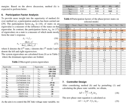
8. Simulation Results
A microgrid consisting of three inverters as shown in Fig. was simulated in Matlab/SimPowerSystem to validate the performance of the proposed control scheme. The converters and inverters are represented by the ideal source models. The
simulation parameters are listed in Table 1. The three
inverters were supplying the full load of 2kW each (local load is 6kW), and at t= 1 s the load was disconnected. The power responses are shown in Fig. 9a. It is clear that the response is well-damped thanks to the proposed controller which is
activated automatically when the DC voltage exceeds 𝑣𝑡𝑟. It
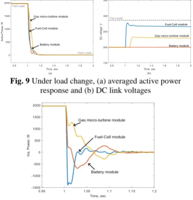
is worth comparing this with the results in Fig. 6 which is for the same system but without the controller been activated. In addition, the DC link voltages in Fig. 9b are bounded and they are below the trip level, which confirms the effectiveness of the proposed strategy. Although, the average power responses in Fig. 9a did not show any reverse flow, the instantaneous power of the Fuel cell has in fact a reverse power and that is shown in Fig. 10. This reverse power flow caused the DC link capacitor to charge.
Trip Level
Battery module Gas micro-turbine module Fuel-Cell module
Full Load
Zero Load
Fuel-Cell module Gas micro-turbine module
Battery module
(a) (b)
Fig. 9 Under load change, (a) averaged active power response and (b) DC link voltages
Fuel-Cell module Gas micro-turbine module
Battery module
Fig. 10 Instantaneous power flow between the inverters
Fig. 11 shows the averaged active power and the DC voltage
responses when the proposed controller’s gain is 𝑃𝑑𝑐=
1 × 10⁻³. The system is unstable and the oscillating
frequency is found to be 314 rad/ sec and this agrees with the prediction from Fig. 8 where the system becomes unstable and the oscillation frequency is 312 rad/sec.
1.227 sec 1.207
sec
Fuel-Cel
l module
(a) (b)
Fig. 11 Averaged power (a) and DC link voltage (b)
responses when𝑃𝑑𝑐= 1 × 10⁻³
To confirm the findings of the analytical approach with regards to the superiority of method (b) over method (a), Fig. 12 shows the responses when the control loop (a) is adopted
with 𝑃𝑑𝑐= 5 × 10⁻³. The gain has been chosen to give the
same ability to limit the DC link voltage as shown in Fig. 9b. It is obvious that the gain is higher than the one used in method (b), which confirms that the method (b) needs less effort to limit the DC voltage. Furthermore, the responses of power and DC link voltage are very oscillatory compared to that in Fig. 9.
Fuel-Cell module
Gas micro-turbine module
Battery module
Trip Level
(a) (b)
Fig. 12 Averaged power (a) and DC link voltage (b) responses when method (a) is used
(a) (b)
Fuel-Cell module Gas micro-turbine module
Battery module
Fuel-Cell module Gas micro-turbine module
Battery module
[image:7.595.305.497.162.255.2]Trip Level
Fig. 13 Experimental averaged power (a) and DC link voltage (b) responses under load dropping
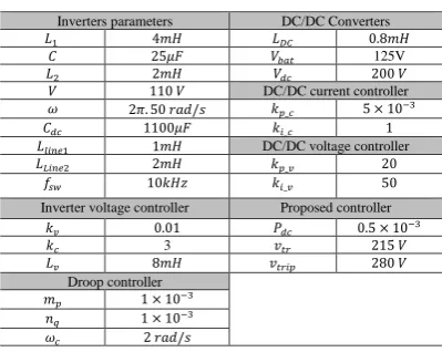
9. Experimental Results
A single phase microgrid consisting of three DC/AC inverters and three DC/DC converters as shown in Fig.1 has been built in the lab. The energy sources are lead-acid battery bank and two fixed DC power sources representing unidirectional energy source. One of the DC/DC converters has been configured as a bidirectional converter to interface the battery while the others were configured as unidirectional boost converters. The control algorithms have been realized using OPAL-RT real time simulator. The parameters of the system
and controllers are shown in Table 5. Fig. 13 shows the active
[image:7.595.304.495.357.552.2] [image:7.595.101.291.485.682.2]7
transients the circulating power between the inverters charged the fuel cell and micro turbine DC link capacitors. The DC voltage of the fuel cell module exceeded the trip level causing a shutdown of the inverter. The proposed controllers using methods (a) and (b) were implemented experimentally to validate the theoretical and simulation results. Both Fig. 14 and Fig. 15 show the averaged active power and the DC link voltage responses during the load changes from 200W to zero when using method (a) and method (b), respectively, for different controller gains values. Obviously, increasing the
controller gain, 𝑃𝑑𝑐= [0.5,1,5] × 10−3 , in both methods
provides faster responses and better performance in limiting the rise of the DC link voltage. However, method (b) in Fig. 15 produces a smoother and highly damped response when it is compared with method (a) in Fig. 14, which has oscillatory responses. This confirms the findings in the previous sections. The oscillatory response in Fig. 14 indicates that the dominant eigenvalues of the system are close to the imaginary axis with higher frequency. For all gain values, method (b) is superior and can provide more reliable and satisfactory responses. The size of the DC link capacitor can influence the DC link voltage transient as discussed in [7]. Therefore, larger capacitor can delay the trip action but still the proposed controller is needed to cease the circulating energy.
Again, choosing high droop gain might equip the inverter with a fast response mitigating the circulating current. However, in some cases, this choice is limited because of:
• droop control loop bandwidth should be less than the
inner loops,
• high droop gains produce oscillations and impact the
stability, and
• high output power inverters require low droop gains
to be within the allowable frequency variations. The proposed controller approved its performance in such cases as a supplementary loop for the traditional droop control and to avoid selecting high gains.
10. Conclusion
This paper has investigated the performance of parallel inverters serving within an islanded microgrid. The study emphasized that, similar droop gains can’t guarantee identical power responses during transient in all cases. If a significant line impedance mismatch is existing, the circulating transient power might by sufficient to degrade the stability. It is found that the proposed phase supplementary loop performs more effectively than the frequency loop in stabilizing the microgrid DC link voltage states. It is worth mentioning that this loop will be activated temporarily during the transient if the DC voltage exceeded a threshold. The steady state error appears just in case of zero load transition. However, it is not a big concern as once a load is connected again, it is enough to discharge this excess energy and to retain a zero error. The theoretical analysis and the performance of the proposed controller have been validated by simulation and experimental results.
(a)
(b)
3 0.5 10
dc
P= − 1 103
dc
P= − 5 103
dc
[image:8.595.333.481.114.359.2]P= −
Fig. 14 Experimental results when method (a) is used
(a)
(b)
3 0.5 10
dc
P= − 1 103
dc
P= − 5 103
dc
P = −
[image:8.595.333.464.409.652.2]8
Table 5 Experimental setup parameters
Inverters parameters DC/DC Converters
𝐿1 4𝑚𝐻 𝐿𝐷𝐶 0.8𝑚𝐻
𝐶 25𝜇𝐹 𝑉𝑏𝑎𝑡 125V
𝐿2 2𝑚𝐻 𝑉𝑑𝑐 200 𝑉
𝑉 110 𝑉 DC/DC current controller
𝜔 2𝜋. 50 𝑟𝑎𝑑/𝑠 𝑘𝑝_𝑐 5 × 10⁻³
𝐶𝑑𝑐 1100𝜇𝐹 𝑘𝑖_𝑐 1
𝐿𝑙𝑖𝑛𝑒1 1𝑚𝐻 DC/DC voltage controller
𝐿𝐿𝑖𝑛𝑒2 2𝑚𝐻 𝑘𝑝_𝑣 20
𝑓𝑠𝑤 10𝑘𝐻𝑧 𝑘𝑖_𝑣 50
Inverter voltage controller Proposed controller
𝑘𝑣 0.01 𝑃𝑑𝑐 0.5 × 10⁻³
𝑘𝑐 3 𝑣𝑡𝑟 215 𝑉
𝐿𝑣 8𝑚𝐻 𝑣𝑡𝑟𝑖𝑝 280 𝑉
Droop controller
𝑚𝑝 1 × 10⁻³ 𝑛𝑞 1 × 10⁻³ 𝜔𝑐 2 𝑟𝑎𝑑/𝑠
11. References
1. 'Ieee Standard for Interconnecting Distributed Resources
with Electric Power Systems, Ieee Standard 1547, P. 16.', 2003.
2. Issa, W., Sharkh, S., Mallick, T., and Abusara, M.,
'Improved Reactive Power Sharing for Parallel-Operated Inverters
in Islanded Microgrids', Journal of Power Electronics, 2016, 16, (3),
pp. 1152-1162.
3. Coelho, E.A., Wu, D., Guerrero, J.M., Vasquez, J.C.,
Dragicevic, T., Stefanovic, C., and Popovski, P., 'Small-Signal Analysis of the Microgrid Secondary Control Considering a
Communication Time Delay', IEEE TRANSACTIONS ON
INDUSTRIAL ELECTRONICS, 2016, PP, (99), pp. 1-1.
4. Zhong, Q.C. and Zeng, Y., 'Universal Droop Control of
Inverters with Different Types of Output Impedance', IEEE Access,
2016, 4, pp. 702-712.
5. Issa, W.R., Khateb, A.H.E., Abusara, M.A., and Mallick,
T.K., 'Control Strategy for Uninterrupted Microgrid Mode Transfer
During Unintentional Islanding Scenarios', IEEE TRANSACTIONS
ON INDUSTRIAL ELECTRONICS, 2017, PP, (99), pp. 1-1.
6. Avelar, H.J., Parreira, W.A., Vieira, J.B., de Freitas,
L.C.G., and Coelho, E.A.A., 'A State Equation Model of a Single-Phase Grid-Connected Inverter Using a Droop Control Scheme with
Extra Phase Shift Control Action', IEEE Transactions on Industrial
Electronics, 2012, 59, (3), pp. 1527-1537.
7. Issa, W., Abusara, M., and Sharkh, S., 'Control of
Transient Power During Unintentional Islanding of Microgrids', IEEE Transactions on Power Electronics, 2014, 30, (8), pp. 4573 - 4584.
8. Guerrero, J.M., De Vicuna, L.G., Matas, J., Castilla, M.,
and Miret, J., 'A Wireless Controller to Enhance Dynamic Performance of Parallel Inverters in Distributed Generation
Systems', IEEE TRANSACTIONS ON POWER ELECTRONICS,
2004, 19, (5), pp. 1205-1213.
9. Ritwik Majumder, B.C., Arindam Ghosh,Rajat
Majumder, Gerard Ledwich and Firuz Zare, 'Improvement of Stability and Load Sharing in an Autonomous Microgrid Using
Supplementary Droop Control Loop', IEEE Transactions on Power
Systems, 2010, 25, (2).
10. Chen, Y.M., Liu, Y.C., Hung, S.C., and Cheng, C.S.,
'Multi-Input Inverter for Grid-Connected Hybrid Pv/Wind Power
System', IEEE TRANSACTIONS ON POWER ELECTRONICS,
2007, 22, (3), pp. 1070-1077.
11. A. P. Sakis Meliopoulos, G.J.C., 'Small Signal Stability
Analysis of the Integrated Power System - Microgrid Model', in, Bulk Power System Dynamics and Control, (2004)
12. Vasquez, J.C., Guerrero, J.M., Luna, A., Rodríguez, P.,
and Teodorescu, R., 'Adaptive Droop Control Applied to Voltage-Source Inverters Operating in Grid-Connected and Islanded Modes',
IEEE Transactions on Industrial Electronics, 2009, 56, (10), pp. 4088-4096.
13. Escobar, G., Mattavelli, P., Stankovic, A.M., Valdez,
A.A., and Leyva-Ramos, J., 'An Adaptive Control for Ups to Compensate Unbalance and Harmonic Distortion Using a Combined
Capacitor/Load Current Sensing', IEEE TRANSACTIONS ON
INDUSTRIAL ELECTRONICS, 2007, 54, (2), pp. 839-847.
14. Zhang, C., Guerrero, J.M., Vasquez, J.C., and Coelho,
E.A.A., 'Control Architecture for Parallel-Connected Inverters in
Uninterruptible Power Systems', IEEE TRANSACTIONS ON
POWER ELECTRONICS, 2016, 31, (7), pp. 5176-5188.
15. Tan, K.T., So, P.L., Chu, Y.C., and Chen, M.Z.Q.,
'Coordinated Control and Energy Management of Distributed
Generation Inverters in a Microgrid', IEEE TRANSACTIONS ON
POWER DELIVERY, 2013, 28, (2), pp. 704-713.
16. Moghadasi, A., Sargolzaei, A., Khalilnejad, A.,
Moghaddami, M., and Sarwat, A., 'Model Predictive Power Control Approach for Three-Phase Single-Stage Grid-Tied Pv
Module-Integrated Converter', in, 2016 IEEE Industry Applications Society
Annual Meeting, (2016)
17. JUAN C. VASQUEZ, J.M.G., JAUME MIRET,
MIGUEL CASTILLA, and LUIS GARCI´A DE VICUN˜ A,
Hierarchical Control of Intelligent Microgrids', IEEE INDUSTRIAL
ELECTRONICS MAGAZINE, (2010)
18. Abusara, M., Guerrero, J.M., and Sharkh, S., 'Line
Interactive Ups for Microgrids', IEEE TRANSACTIONS ON
INDUSTRIAL ELECTRONICS, 2013, (99), pp. 1-8.
19. Mahmood, H., Michaelson, D., and Jin, J., 'Control
Strategy for a Standalone Pv/Battery Hybrid System', in, 38th
Annual Conference on IEEE Industrial Electronics Society -IECON 2012 (2012)
20. Al Badwawi, R., Issa, W., Mallick, T., and Abusara, M.,
Power Management of Ac Islanded Microgrids Using Fuzzy Logic', 8th IET International Conference on Power Electronics, Machines and Drives (PEMD), (2016)
21. Kolli, A., Gaillard, A., De Bernardinis, A., Bethoux, O.,
Hissel, D., and Khatir, Z., 'A Review on Dc/Dc Converter
Architectures for Power Fuel Cell Applications', Energy Conversion
and Management, 2015, 105, pp. 716-730.
22. Mane, S., Kadam, P., Lahoti, G., Kazi, F., and Singh,
N.M., 'Optimal Load Balancing Strategy for Hybrid Energy Management System in Dc Microgrid with Pv, Fuel Cell and Battery
Storage', in, 2016 IEEE International Conference on Renewable
Energy Research and Applications (ICRERA), (2016)
23. Ziaeinejad, S., Sangsefidi, Y., and Mehrizi-Sani, A., 'Fuel
Cell-Based Auxiliary Power Unit: Ems, Sizing, and Current
Estimator-Based Controller', IEEE Transactions on Vehicular
Technology, 2016, 65, (6), pp. 4826-4835.
24. Issa, W., Abusara, M., Sharkh, S., and Tapas, M., 'A Small
Signal Model of an Inverter-Based Microgrid Including Dc Link
Voltages', in, 17th European Conference on Power Electronics and
Applications, (EPE 2015, 2015)
25. Pogaku, N., Prodanovic, M., and Green, T.C., 'Modeling,
Analysis and Testing of Autonomous Operation of an
Inverter-Based Microgrid', IEEE TRANSACTIONS ON POWER
ELECTRONICS, 2007, 22, (2), pp. 613-625.
26. Rasheduzzaman, M., Mueller, J., and Kimball, J., 'An
Accurate Small-Signal Model of Inverter-Dominated Islanded
Microgrids Using Dq Reference Frame', IEEE Journal of Emerging
and Selected Topics in Power Electronics, 2014.
27. Abusara, M.A., Sharkh, S.M., and Guerrero, J.M.,
'Improved Droop Control Strategy for Grid-Connected Inverters', Sustainable Energy, Grids and Networks, 2015, 1, pp. 10-19.
28. Josep M. Guerrero, L.G.d.V., José Matas, Miguel Castilla
and Jaume Miret, 'Output Impedance Design of Parallel-Connected
Ups Inverters with Wireless Load-Sharing Control', IEEE
TRANSACTIONS ON INDUSTRIAL ELECTRONICS, 2005, 52, (4).
29. Zhang, C., Coelho, E.A.A., Guerrero, J.M., and Vasquez,
J.C., 'Modular Online Uninterruptible Power System Plug N Play
Control and Stability Analysis', IEEE TRANSACTIONS ON