Copyright © 2015 CTTS.IN, All right reserved
Design and Implementation of Low Consumption FIR
Bandpass Filters for Matching Biological Data with FPGA
Reza Shoeibi
Master Degree, Department of Electrical, Khorasan-e-Razavi Science and Research branch, Islamic Azad University, Neyshabur, Iran, Email ID : [email protected]
Nasser Mehrshad (Corresponding Autor)
Assistant Professor, Birjand of University, Email ID : [email protected]
Abstract — Biological Sequences (protein or DNA) are
vital in Bioinformatics. These like string adaptation in context of biologics data and a set of protein or DNA sequences are used for discovering evolutionary relationship. In this study we present FIR bandpass digital filter with low power consumption for matching biological sequences. We proposed that instead of using collectors in parallel, design filters so that the collectors will be in series that lead to less power consumption. First the programs of these bandpass filters are designed by MATLAB then MATLAB codes are converted to VHDL by CONVERTOR HDL. Bandpass FIR filter proposed in FPGA ARTIX-7 XC7A100T segment are applied and Synthesized by XILINX ISE 14.2. The power consumption has been analyzed by Xilinx XPower analyzer.
Keyword — Biological Sequences, Matching, DNA,
FPGA, FIR bandpass Filter, ARTIX-7 .
1. I
NTRODUCTIONBioinformatics is one of the bioscience field which deals with storage method, recovery and analyzing bio data such as DNA. This process includes of finding gene in DNA sequence of different organism, different methods found for anticipating new protein structure and function and RNA structural sequence and protein Sequence Clustering which related to the family. Genetics informations of any cell are stored in a long molecule called “DESOXY ribonucleic acid” or DNA. DNA is a polymer which is structured from four monomers. DNA is a long sequence of Nucleotide base pairs which is summarized in a character string with “A,C,G,T” alphabet. A is the abbreviation of Adenine, C is the abbreviation of Cytosine, G (Guanine) and T (Thymine). In this way scientist used these four alphabets for showing DNA molecule. They called this long sting “sequence”. In fig. 1, DNA and RNA are been shown. The different between these two is that DNA has two twisted helix but RNA has one.
Fig.1. Figure DNA and RNA [1]
Fig.2. Tuesday substages of FPGA-based accelerator for the matching word BLASTN [7]
Biological sequences have an algorithm that if implement in hardware will be very useful. FIR filters is one of the blocks that are used in implementing bio sequence in hardware. FIR digital filter are used in most of the digital signal processing program. Parallel process could be applied in FIR digital filters in order to lower consumption of main filter. Traditionally, using parallel process in a FIR filter includes of repeating hardware unit which are exist in main filters [8]. One of the FIR filter implementation is using of applied collectors and connected shifts [9]. These are used a common change in the elimination algorithm of expression for decreasing some of the collector. In [10] a new method is recommended for designing a method by low consumption digital band. Their method is to optimize bit width from coefficient of each filter. They define the problem of optimized band width from coefficient of each filter. In study [11] writers try to propose a FIR filter that capable of programming which has low consumption. Asymptomatic multipliers are used for implementing these filters and function rate of switching is decreased. The rest of this article is as following: section 2 is FIR filter theory, section 3 is architecture platform, section 4 is design of FIR filter and section 5 is conclusion.
2.
FIR
F
ILTERT
HEORYDigital filters are used widely for indentifying system, adjustors, noise elimination, dialogue signal code and etc. these filters increase date sending rate and decrease circuit volume. General equation of digital filter are as following (1):
Y(n) = - + (1) Two states of equation in IIR and FIR are:
- Finite impulse response filter; without feedback: [ak]=0 - Finite impulse response filter: with feedback: : [ak] ≠0 A FIR system with example response is a unit with limited length, in other words output in this system is a combination of current input and M of previous input example. So output of FIR system in terms of input example is as following:
Y(n) = b0 x(n) + b1x(n-1)+….+bM x(n-M)
Y(n) = (2)
In this matters a FIR filter of M degree are defined by multiple M+1.
Equation 2 is a convolution between X(n) and h(n). If conversion equation 1 parties arepremised Z, conversion function of FIR system is:
H(z) = z-r = z-r (4) If z substitute with ejw, frequency response of FIR system will be obtained.
H(ejw) = e-jwr (5) In FIR, output signals of filter adjusted after input signal of zero to non zero, non zero could be premised in limited number. FIR filter are always stable. FIR filters are limited which is a necessary feature for linear phase. The most common digital filter is linear time-invariant filter. LTI digital filter is generally is classified as Finite impulse response (for example FIR) or infinite impulse response. As it convey from their names, a FIR filter includes of Finite number of sample values, reduction of top convolution to infinite sum in output example. FIR with constant coefficient of a digital filter is LTI. FIR outputs in terms of priority or L length are a input time series X[N] which are given by a Limited Edition of convolution in (6): in means:
y[n] = x[n] * f [n] = (6) F [0] ≠ 0 is filtered by F [L - 1] ≠ 0 which is L. these are matched with FIR Impulse response. Z impression sometimes are easier for LTI systems.
Y (Z) = F(Z) X(Z) (7) In which F(z) function is transfer function impressed in Z domain :
F (Z) = -K (8)
3. T
ECHNOLOGYA
RTIX-7
If you are using In this article we presented a succinct introduction about applied technology in FPGA ARTIX-7. Newest generation of series 7 machine is created in 28nm process technology which has the lowest cost and consumption of FPGA in products such as portable medical equipment, army radio and compact wireless infrastructure. The total power consumption are 50% lesser than previous generation. Also FPGA ARTIX-7 family have other advantage which we present in following [12]:
- The best performance for DD3, DSP, parallel and I/O serial
- 930 GMACs process of DSP for high quality image and optimize RF signal
- Small form Factor for devices as size as laptop and tablet
- Over 50,000 logical cells in a 10*10 mm package - Integrated Memory Interface for easy access to video and data
Copyright © 2015 CTTS.IN, All right reserved
4. I
MPLEMENTATIONF
ILTERFIR
4.1 FIR band-pass filter implemented in MATLAB Design of filter means making the filter coefficients so that meet some filtering essentials. Implementation of filter means choosing and applying of a special filter structure on these coefficients. Just after designing and implementation we could filter the data. There are different methods for designing FIR filters. In table (1) order used for FIR filter designing is shown in different way.
Table (1) Commands used to design FIR filters to different methods
Filter design methods
Description Instruction
s for use
Windowing
Applying the inverse Fourier transform filter is ideal for cutting window
Firl1,firl2, kaiserord Multiband with
Transition Bands
Method of least squares on the band frequency range
Firls,firpm, firpmord
Constrained Least Squares
Minimization sum of squared errors over the entire frequency range in order to bound the maximum error
Firels, fircls1
Arbitrary Response
The desired response, including nonlinear phase and mixed responses
Cfirpm
Raised Cosine
Low-pass response with
smooth sinusoidal response Firrcos
Our desired filter is FIR bandpass filter which its code is written in MATLAB.
clc clear close all Fs=50000000; Ap=1; As=45; M=[0 1 0];
F=[10000000, 12000000, 16000000, 18000000] ; dp=(10^(Ap/20)-1)/(10^(Ap/20)+1);
ds=10^(-As/20); dev=[ds dp ds];
[N1, F0, M0, W] = remezord(F, M, dev, Fs); [b delta] = remez(N1, F0, M0, W);
[H, f] = freqz(b, 1, 1024, Fs); mag = 20*log10(abs(H)); plot(f, mag),
grid on
xlabel('Frequency (Hz)') ylabel('Magnitude (Db)')
Fig. 3, is designed FIR filter in MATLAB which limited in 1 to 1.8 MH frequencies.
0 0.5 1 1.5 2 2.5
x 107 -100
-80 -60 -40 -20 0 20
Frequency (Hz)
M
a
g
n
it
u
d
e
(
d
B
)
Fig. 3 . FIR bandpass filter
4.2 FIR filter design with FPGA
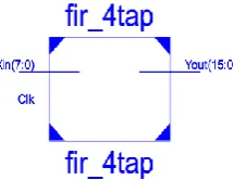
In this article we converted code that is written in MATLAB by convertor hdl to vhdl in order to filter FIR bandpass. Then VHDL code is applied on FPGA ARTIX-7 XC7A100T unit by XILINX ISE 14.2 software. Bandpass FIR filter has a fir-4tp main core which is shown in fig. 4. This main core is included of three DFF1, DDF2 and DDF3 program.
Fig. 4 . Block diagram FIR bandpass filter
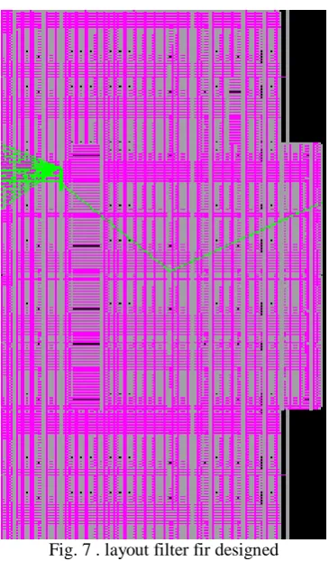
In fig. 5 and 6 respectively you see RTL schematic and designed FIR bandpass technology which are obtained by ISE 14.2 software. As you see in RTL schematic three DPS processor are included.
Fig. 5 . RTL schematic FIR bandpass filter
Fig. 6 . Schematic technology band-pass filter FIR
Copyright © 2015 CTTS.IN, All right reserved In table (2) the results of output FIR digital band-pass
filter are presented which includes of numbers of block and the other used factor for filter design.
Table (2) The results of the FIR filter designed Available Used
Slice Logic Utilization
210 25
Number of bonded
32 1
Number of BUFG/BUFGCTRLs
240 4
Number of DSP48E1s
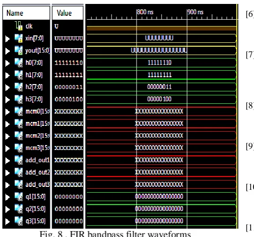
In fig. 8, the wave of output and input of FIR bandpass filter are designed. The shape of the wave is drawn by ISE 14.2 software.
Fig. 8 . FIR bandpass filter waveforms
Also in this article the power of filters are shown. In table (3), the power are obtained in 3 frequencies.
Table (3) power obtained by bandpass filter FIR
100 MHZ 75 MHZ
50 MHZ 25 MHZ
Frequency
220 mW 186 mW
155 mW 123 mW
Power obtained
5. C
ONCLUSIONIn this article we designed a low consumption FIR bandpass filter for Maching biological data. Biological Sequences include of DNA data which are designed by digital filters and could be adapted to DNA information. We proposed that instead of using collectors in parallel, design filters so that the collectors will be in series that lead to less power consumption.. Proposed FIR bandpass filter are implemented by FPGA ARTIX-7 XC7A100T and power consumption is analyzed by Xilinx XPower analyzer. The results of Proposed filter stimulation with low consumption was favorable.
R
EFERENCE[1] Tortora G.J and Derrickson B.H, “Principles of Anatomy and Physiology”, 2011.
[2] Hein J , “A new method that simultaneously aligns and reconstructs ancestral sequences for any number of homologous sequences”, pp. 649-668, 1989.
[3] Bains W , “MULTAN: a program to align multiple DNA sequences”, Vol.14, No.1, , pp. 159-177, 1986. [4] Dandass Y, Burgess S, Lawrence M, and Bridges S,
“Accelerating String Set Matching in FPGA Hardware for Bioinformatics Research, BMC Bioinformatics”, BMC Bioinformatics, Vol. 9, pp. 1-11, 2088.
[5] Segundo, E.J.N. , Nedjah, N. , de Macedo Mourelle, L., “A Scalable Parallel Reconfigurable Hardware Architecture for DNA Matching”, IEEE Fourth Latin American Symposium on Circuits and Systems (LASCAS), pp. 1-4, 2013.
[6] Tom´ aˇ sMart´ınek, Matej L. , “Architecture Model for Approximate Tandem Repeat Detection”, IEEE, International Conference on IEEE (ASAP), pp. 239-242, 2011.
[7] Chen Y, Schmidt B, Douglas L. Maskell, “Reconfigurable Accelerator for the Word-Matching Stage of BLASTN”, IEEE TRANSACTIONS ON VERY LARGE SCALE INTEGRATION (VLSI) SYSTEMS, Vol. 21, NO. 4, pp. 659-669, APRIL 2013. [8] AHMED F. SHALASH, KESHAB K. PARHI, “Power
Efficient Folding of Pipelined LMS Adaptive Filters with Applications”, Journal of VLSI Signal Processing, pp. 199-213, 2000.
[9] Mirzaei Sh., Hosangadi A, Kastner R., “FPGA Implementation of High Speed FIR Filters Using Add and Shift Method”, IEEE, International Conference on Computer Design, pp. 308-313, 2006.
[10] TARUMI K, HYODO A, MUROYAMA M,
YASUURA H, “A design method for a low power digital FIR Flter indigital wireless communication systems”, 2004.
[11] Shah, F.A , Jamal H , Khan, M.A, “Reconfigurable Low Power FIR Filter based on Partitioned Multipliers”, IEEE, International Conference on Microelectronics, pp. 87-90, 2006.
[12] www.xilinx.com
A
UTHOR’
SP
ROFILEReza Shoeibi