Load Controlled Adaptive P&O MPPT
Controller PV Energy Systems
L R Shanmugasundaram 1, K Sarbham 2
P.G. Scholar, Department of Electrical Engineering, SIETK, Puttur, A.P., India1
Assistant Professor, Department of Electrical Engineering, SIETK, Puttur, A.P., India2
ABSTRACT: A adaptive pert urb and observe (P&O) maximum power point tracking (MPPT) algorithm is proposed to track the maximum power under sudden changes in irradiance. The proposed method consists of three algorithms, namely current perturbation algorithm (CPA), adaptive control algorithm (ACA), and variable perturbation algorithm (VPA). CPA always tries to operate the photovoltaic (PV panel at maximum power point (MPP). ACA sets the operating point closer to MPP, only if the operating limits are violated. These operating limits are expressed in terms of the operating current range of the PV panel and the sudden changes in irradiance. The perturbation size based on polarity of change in power.VPA is dynamically reduced.
KEYWORDS: adaptive p&o mppt algorithm, current perturbation algorithm, variable perturbation algorithym, adaptive perturbation algorithm, Boost converter.
I. INTRODUCTION
The main aim of the maximum power point (MPP) tracking (MPPT) algorithms is to achieve fast and accurate tracking performance and minimize oscillations due to varying weather conditions. A comparative study on MPPT techniques for photovoltaic (PV) power systems is reported in [1] and [2]. Among different MPPT algorithms much focus has been on perturb and observe (P&O) [3], hill climbing[4] , and incremental conductance[5] (INC) methods . In, a survey of P&O techniques has been presented weather conditionsIt has been shown that the existing techniques suffer from oscillations, complexity, designer dependency, and more computational effort. By reducing the fixed perturbation size these oscillations can be minimized, but it takes relatively more time to reach MPP. The solution to this conflicting situation is to have a variable step size as suggested in[6].
In the P&O method, the operating point oscillates around the MPP giving rise to the wastage of some amount of available energy. These oscillations can be minimized by reducing the fixed perturbation size, but it takes relatively more time to reach MPP. The solution to this conflicting situation is to have a variable step size as suggested . Although the implementation of these methods are simple,it is not very accurate and rapid, since the effects of temperature and irradiation are not taken into consideration. Patel and Agarwal [7] proposed a variable perturb by adopting four power ranges. In each range, a specific perturb value is used; hence, the method is not fully adaptive..
Several methods are proposed[7] to address these issues by considering adaptive perturbation An INC method is based on the fact that the slope of the PV array power curve is zero at MPP, negative on the right, and positive on the left of the MPP.The INC method inherits the same problems as P&O, namely the tradeoff between the speed and oscillations. In [4], the author claims that the INC method is prone to failure in case of large changes in irradiance’
ISSN(Online): 2319 - 8753
ISSN (Print) :2347 - 6710
I
nternational
J
ournal of
I
nnovative
R
esearch in
S
cience,
E
ngineering and
T
echnology
(An ISO 3297: 2007 Certified Organization)
Vol. 4, Issue 5, May 2015
II. CONVENTIONALMETHOD
In the conventional system we are using p&o mppt algorithm.the systemsuffer from oscillations, complexity, designer dependency, and more computational effort. In the P&O method[3], the operating point oscillates around the MPP giving rise to the wastage of some amount of available energy. These oscillations can be minimized by reducing the
fixed perturbation size, but it takes relatively more time to reach MPP.the implementation of perturb and observe (P&O), hill climbing , and incremental conductance (INC) method[5]are simple.In our consideration the irrsdiation and the tempatature efforts are not taken.so we are proposing a variable perturb by adopting four power ranges.
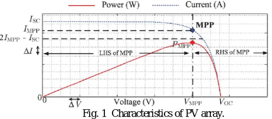
In existing system the incremental conductance method is also have some draw backs. which is based on the fact that the slope of the PV array power curve is zero at MPP, negative on the right, and positive on the left of the MPP.The INC method inherits the same problems as P&O, namely the tradeoff between the speed and oscillations.
Fig. 1 Characteristics of PV array.
In the another mppt algorithm MPP current is continuously monitored with respect to the short circuit Current. This method is well known as the fractional short circuit current [(FSCC) or fractional open circuit voltage] method. Since this method approximates a constant ratio, its accuracy cannot be guaranteed under varying weather conditions. Several methods have been proposed To overcome the above-mentioned drawbacks using artificial intelligence (AI)-based algorithms such as neural network (NN) and fuzzy logic controller (FLC).
but in existing system these methods also having some drawbacks such as the requirement of large data storage and extensive computation. For instance, NN requires a large amount of data for training, which is the major constraint. Similarly, FLC requires extensive computation to deal various stages.Here the MPP continuously changes with atmospheric conditions in real time so low-cost hardware processors cannot be used for these applications.
III.PROPOSEDMETHOD
To overcome the conventional p&o mppt method drawbacks we proposed adaptive p&o mppt method.In this proposed method having three algorithm namely current perturbation, adaptive control,and variable perturbation.the proposed system adaptive p&o mppt algorithm is shown in bellow fig.2
Fig.2.flow chart of proposed mppt algorithm
To track the voltage and current of the pv arraywe are using mppt algorithm, where maximum output
power is obtained under a specific irradiance and temperature.fig 2 shows the proposed method is devided into three algorithm
1) Current Perturbation Algorithm (CPA):
A conventional P&O algorithm concept is used in this algorithm but it considers current perturbation instead of voltage perturbation to speed up the tracking performance.the current perturbation algorithm is shown in fig 2
2) Adaptive Control Algorithm (ACA):
ISSN(Online): 2319 - 8753
ISSN (Print) :2347 - 6710
I
nternational
J
ournal of
I
nnovative
R
esearch in
S
cience,
E
ngineering and
T
echnology
(An ISO 3297: 2007 Certified Organization)
Vol. 4, Issue 5, May 2015
3) Variable Perturbation Algorithm (VPA)
whenever the operating point crosses the MPP to minimize the oscillations around MPP this algorithm reduces the perturbation size dynamically. It provides the fine tuning of perturbation size.
REALIZATION OF PROPOSED MPPT ALGORITHM USING BOOST CONVERTER:
The proposed MPPT algorithm is realized using a boostconverter. The PV panel is connected to the boost converter as shown in Fig. 3
Fig.3 Circuit diagram of pv system with mppt controller
In proposed system pv panel is connected across the boost converter.In pv panel energy is depending upon the weather conditions .so here we have different types energy in pv panel. which is damaging the system,we have constant energy here .so we implement adaptive p&o mppt algorithm. By using pwm we can apply the gate pulses in system. which connected to IGBT switch shown in fig 3 .
IV.SIMULATIONMODELANDRESULTS
Fig. 4 Simulation model
The adaptive p&o mppt algorithm in simulink is shown in bellow fig.5
Fig.5 Mppt algorithm simulink
ISSN(Online): 2319 - 8753
ISSN (Print) :2347 - 6710
I
nternational
J
ournal of
I
nnovative
R
esearch in
S
cience,
E
ngineering and
T
echnology
(An ISO 3297: 2007 Certified Organization)
Vol. 4, Issue 5, May 2015
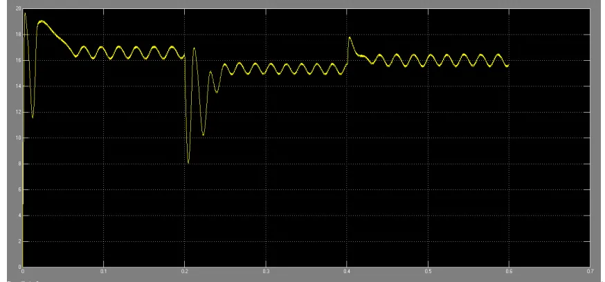
The pv panel current waveform is shown in bellow fig.6
Fig.6 pv panel current waveform (current vs time)
The pv pannel power waveform is shown in fig.7
Fig.7 pv panel power waveform (power vs time)
Fig.8 simulink waveform of mppt (power vs time)
ISSN(Online): 2319 - 8753
ISSN (Print) :2347 - 6710
I
nternational
J
ournal of
I
nnovative
R
esearch in
S
cience,
E
ngineering and
T
echnology
(An ISO 3297: 2007 Certified Organization)
Vol. 4, Issue 5, May 2015
V. CONCLUSION
In a variable perturbation size adaptive p&o mppt algorithm was proposed for sudden changes in irradiance and PV current limit violation. The proposed method has the following three features: 1) steadily tracks the MPP under normal conditions, 2) speeds up the dynamic performance under sudden operating limits violation, and 3) provides variable perturbation to reduce the oscillations around MPP. These three features are accomplished using three algorithms namely CPA, ACA, and VPA, respectively. Unlike the conventional P&O, the proposed algorithm has faster response with reduced oscillations around MPP. The computational efforts caused due to the derivatives as explained in INC method are absent. It tracks true maximum power, unlike the fractional open circuit voltage and FSCC methods. Also, it does not require a large amount of data(storage) for training and extensive computation to deal various stages, as required by FLC and NN. The simulation and experimental studies show that the proposed algorithm gives faster response than the conventional algorithms.
REFERENCES
[1] T. Esram and P. L. Chapman, “Comparison of photovoltaic array maximum power point tracking techniques,” IEEE Trans. Energy Convers., vol. 22, no. 2, pp. 439–449, Jun. 2007.
[2] B. Subudhi and R. Pradhan, “A comparative study on maximum power point tracking techniques for photovoltaic power systems,” IEEE Trans.Sustain. Energy, vol. 4, no. 1, pp. 89–98, Jan. 2013.
[3] A. K. Abdelsalam, A. M. Massoud, S. Ahmed, and P. Enjeti, “Highperformance adaptive perturb and observe MPPT technique for photovoltaic-based microgrids,” IEEE Trans. Power Electron., vol. 26, no. 4, pp. 1010–1021, Apr. 2011.
[4] S. B. Kjaer, “Evaluation of the hill climbing and the incremental conductance maximum power point trackers for photovoltaic power systems,” IEEE Trans. Energy Convers., vol. 27, no. 4, pp. 922–929, Dec. 2012.
[5] F. Liu, S. Duan, F. Liu, B. Liu, and Y. Kang, “A variable step size INC MPPT method for PV systems,” IEEE Trans. Ind. Electron., vol. 55, no. 7, pp. 2622–2628, Jul. 2008.
[6] C. W. Tan, T. C. Green, and C. A. Hernandez-Aramburo, “An improved maximum power point tracking algorithm with current-mode control for photovoltaic applications,” in Proc. Int. Conf. Power Electron. Drives Syst., vol. 1, 2005, pp. 489–494.