NOTICE
The information contained in this document is believed to be accurate in all respects but is not warranted by Mitel Corporation (MITEL). The information is subject to change without notice and should not be construed in any way as a commitment by MITEL or any of its affiliates or subsidiaries. MITEL and its affiliates and subsidiaries assume no responsibility for any error or omissions in this document. Revisions of this document or new editions of it may be issued to incorporate any such changes.
Nothing in this document may be reproduced in any manner, either wholly or in part for any use whatsoever, without written permission from Mitel Corporation.
Host Command Interface, HCI, MITEL, MiTAI, Nupoint Messenger, Nupoint Voice, Nupoint Fax, Nupoint Agent, OnePoint Messenger, SUPERSET, SX-200 and SX-2000 are trademarks of Mitel Corporation. Windows 95 and Windows NT are trademarks of Microsoft Corporation. INTEL and Pentium are trademarks of Intel Corporation.
All other product names specified in this document are trademarks of their corresponding owners.
OnePoint Messenger/SX-2000 Integration Guide OnePoint Messenger Release 2.0 Part Number 9164-120-116-NA, Issue 2
December 14, 2000
,, Trademark of MITEL Corporation.
Copyright 2000, MITEL Corporation. All rights reserved.
OnePoint Messenger/SX-2000 Integration Guide, Issue 2, 12/14/00 iii
Table of Contents
List of Tables... viii
1. OnePoint Messenger/SX-2000 Integration Overview ... 9
What Is OnePoint Messenger and Unified Messaging? ...9
Telephony Server... 11
Telephony Server Peripherals ... 11
What is PBX Integration? ...12
Integration Benefits ... 13
Call Processing Overview...14
Task Overview...15
Message Waiting ... 16
Integration Strategy ...16
Required Skills ...19
How to Use This Guide ...19
Organization of this Manual... 20
Other Documentation ...21
Using Electronic and Printed Versions... 21
Conventions Used in This Guide ... 22
Terms Used for Keys, Commands, and Buttons...22
Images and Tables ...22
Type Used in Commands and Screen Output ... 23
List Styles ... 23
Note and Caution Styles ...23
Other Text Styles ... 23
Contacting Technical Publications ...24
2. Configuring the SX-2000 LIGHT ... 25
OnePoint Messenger Requirements of the PBX ...25
Dialed Services ...26
User Services ... 26
iv Table of Contents
Directory Number 7999...29
Forms Checklist ...29
Class of Service Options ...31
Class of Service for Stations ...31
Class of Service for Trunks...31
System Options Assignment...32
Setting Up the AFC Card Connection ...32
Dimension and Feature Selection ...32
Cabinet Assignment...33
System Configuration...33
Digital Link Descriptor Assignment ...34
Digital Link Assignment ...36
Trunk Programming ...36
MSDN/DPNSS/DASSII Trunk Circuit Descriptor Assignment...36
Trunk Service Assignment...37
Trunk Assignment ...37
Assigning Trunk Groups to the Message Center...38
Creating Directory Number 7999 ...39
Programming Voice Mail Ports...39
Assigning a Hunt Group to the Message Center ...39
System Speed Call Assignment...40
Call Reroute Assignment ...41
Call Reroute Always Alternative Assignment...41
Automatic Route Selection (ARS) Assignment ...42
Route Assignment ...42
Class of Restriction (COR) Group Assignment ...43
Programming the Automated Attendant (Receptionist) ...43
Programming Fax on Demand ...44
3. Installing Line Cards in the Telephony Server... 45
What Hardware Do You Need on the Telephony Server? ...45
Fiber Optic Cable Specifications ...46
Preparing the Installation Site ...47
Accommodating the TS-800 Telephony Server Tower ...47
OnePoint Messenger/SX-2000 Integration Guide, Issue 2, 12/14/00 v
Setting MVIP Termination ... 48
Connecting Cards through an MVIP Cable ... 49
Setting Interrupts and Base Addresses ...49
Installing Brooktrout Fax Cards ...51
Installing and Configuring an NMS Card ...52
Creating the AG Configuration File ... 53
Running the NMS AG Configurator Program ...53
Using Notepad to Edit AG.cfg ...56
Enabling the Mitel AFC Card with MiTAI ...57
Installing the AFC Card ...57
Configuring the NMS and CTI Software ...58
Making and Verifying Connections ...59
Verifying Fiber Link Synchronization between the AFC and PBX ... 59
4. Installing Mitel Telephony Application Interface (MiTAI) ... 61
What You Need to Complete this Chapter ...61
MiTAI Installation ...61
Installing MiTAI on the Telephony Server ... 61
Editing the Server Hosts File ... 65
Checking the Operation of the MiTAI Link to the PBX...65
Where Now? ...66
5. Configuring OnePoint Messenger PBX Integration Software . 67
Integrating the Telephony Server with the SX-2000 PBX ...67
Show N Tel Setup Procedures ...68
Configuring Show N Tel with a PBX ...68
Editing the SNT Parameters Tab ...71
Assigning Programs to Lines ...72
Configuring and Testing the Notification Server ... 74
Using the SNT Manager Runtime Tab to Assign Telephony Applications...76
Setting Telephone User Interface Parameters ...78
Editing the Telsrvr.ini File... 80
Testing Telephony Server Start and Stop...80
Configuring OnePoint Messenger to Auto-start ...81
vi Table of Contents
Reassigning Lines to Other Applications ...82
6. Troubleshooting the Integration ... 85
System Validation Tests ...85
Running Validation Tests ...85
Testing the Network Connection...86
A. PBX Integration Worksheet ... 87
Workflow Overview...87
PBX Integration Worksheet Fields ...88
Numbering Ports...89
Creating Hunt Groups ...89
PBX Integration Worksheet (Sample of a completed worksheet) ...90
PBX Integration Worksheet ...91
OnePoint Messenger/SX-2000 Integration Guide, Issue 2, 12/14/00 vii
List of Figures
Figure 1-1 Network Diagram ... 10
Figure 1-2 Hunt Group Mapping to Telephony Server Ports ... 18
Figure 2-1 Trunk and Extension Topology ... 28
Figure 3-1 Windows NT Diagnostics, Resources Tab, IRQ List ... 50
Figure 3-2 NMS AG Configurator Main Screen ... 54
Figure 3-3 NMS Board Configuration Screen ... 55
Figure 3-4 AFC Card ... 58
Figure 4-1 MiTAI Settings Dialog, Hardware Tab ... 63
Figure 4-2 MiTAI Settings Dialog, Software Tab ... 64
Figure 5-1 Show N Tel Manager, Switch/CTI Tab ... 69
Figure 5-2 Show N Tel Manager, Configure CTI, Device Map Tab ... 70
Figure 5-3 Show N Tel Manager, Parameters Tab ... 71
Figure 5-4 Show N Tel Manager, Runtime Tab ... 77
Figure 5-5 Show N Tel Runtime Tab, Assign Phone System ... 78
viii Table of Contents
List of Tables
Table 2-1 PBX Trunks Mapped to SNT Lines and Applications ... 28
Table 2-2 SX-2000 Forms Checklist ... 30
Table 2-3 Class of Service Options Assignment, COS 10 ... 31
Table 2-4 Class of Service Options Assignment, COS 21 ... 31
Table 2-5 System Options Assignment ... 32
Table 2-6 Dimension and Feature Selection ... 32
Table 2-7 Cabinet Assignment ... 33
Table 2-8 System Configuration ... 34
Table 2-9 Link Descriptor Assignment ... 35
Table 2-10 Digital Link Assignment ... 36
Table 2-11 MSDN-DPNSS-DASSII Trunk Circuit Descriptor Assignment ... 36
Table 2-12 Trunk Service Assignment ... 37
Table 2-13 Trunk Assignment ... 38
Table 2-14 Trunk Group Assignment ... 39
Table 2-16 System Speed Call Assignment ... 40
Table 2-15 Hunt Group Assignment... 40
Table 2-17 Call Rerouting Assignment... 41
Table 2-18 Call Rerouting Always Alternative Assignment ... 41
Table 2-19 Automatic Route Selection Assignment ... 42
Table 2-20 Route Assignment ... 42
Table 2-21 Class of Restriction Group Assignment ... 43
Table 2-22 Trunk Group Assignment for Automated Attendant ... 43
Table 2-23 Trunk Group Assignment for Fax on Demand ... 44
OnePoint Messenger/SX-2000 Integration Guide, Issue 2, 12/14/00 9
1. OnePoint Messenger/SX-2000
Integration Overview
This chapter provides an overview of the components, tasks, and ben-efits of the integration between the Mitel SX-2000™ PBX and the OnePoint Messenger™ Telephony Server to create a unified messag-ing environment. It includes details on configurmessag-ing the PBX to sup-port Telephony Server functions, installing the line cards in the Telephony Server, and configuring integration software on the Tele-phony Server, including setting up teleTele-phony applications.
This chapter also provides information about the organization and styles used in this book, and about other related documentation. This chapter contains the following sections:
What Is OnePoint Messenger and Unified Messaging?
OnePoint Messenger is a software suite that, when combined with other hardware and software products, provides a unified messaging environment. Unified messaging is the combination of telephone messages, fax, and e-mail on one mail server. The OnePoint
Section Page
What Is OnePoint Messenger and Unified Messaging? 9
What is PBX Integration? 12
Call Processing Overview 14
Task Overview 15
Required Skills 19
How to Use This Guide 19
Other Documentation 21
10 Chapter 1, OnePoint Messenger/SX-2000 Integration Overview
Messenger server software is installed on two Microsoft Windows NT Server 4.0 systems:
• The OnePoint Messenger Exchange Extension is installed on the computer running Microsoft Exchange (“the Exchange Server”) to support unified messaging on Exchange.
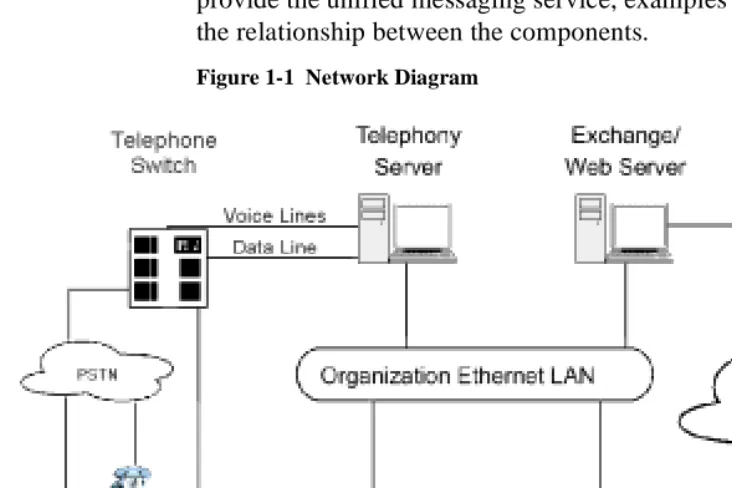
• A large suite of software components providing messaging and maintenance services are installed on the Telephony Server, which handles communication between the telephony network and Microsoft Exchange.
The network diagram in Figure 1-1 shows the major components that provide the unified messaging service, examples of the clients, and the relationship between the components.
Figure 1-1 Network Diagram
See Chapter 1 in the OnePoint Messenger Administrator Guide for a detailed system overview, a summary of each of the hardware and software components, and an overview list of tasks. Chapter 1 in the
OnePoint Messenger User Guide also has a basic system overview
What Is OnePoint Messenger and Unified Messaging? 11
Telephony Server
In these guides, “Telephony Server” is used to refer to the collection of OnePoint Messenger telephony applications that reside on “the Telephony Server” (the computer), while “the Telephony Server” refers to the computer running the Windows NT Server 4.0 operating system. The backplane of the Telephony Server contains the tele-phony “line cards” that provide the connection to the PBX. To pro-vide the ability to edit system greetings and the Text-to-Speech dictionary, you can add a multimedia setup to the Telephony Server, but, administrators typically use a separate system on the LAN for multimedia editing.
The OnePoint Messenger software on the Telephony Server is com-prised of a group of Windows NT Server applications that, among other tasks, provide the information conduit between the PBX and Microsoft Exchange. Those telephone call routing and messaging services include:
• Controlling what happens to calls that are not answered and pro-viding the caller the ability to leave and retrieve voice messages
• Providing digitization and compression of telephone messages for storage on Exchange or forwarding to VPIM accounts, and also reverse transcoding of messages saved on Exchange back to callers and VPIM accounts
• Enabling OnePoint Messenger subscribers (“users”) to retrieve and reply to e-mail messages that are read to them using the text-to-speech (TTS) capabilities of Telephony Server
• Providing advanced fax handling features, including routing e-mail to fax machines and a Fax on Demand service; see Chapter 4 of the OnePoint Messenger Administrator Guide for a discussion of OnePoint Messenger fax features.
Also included on the Telephony Server is a group of OnePoint Mes-senger support programs. For an overview on them and related tasks, see Chapter 1 in the OnePoint Messenger Administrator Guide. Then see Chapter 5 in that guide for operational details.
Telephony Server Peripherals
12 Chapter 1, OnePoint Messenger/SX-2000 Integration Overview
and voice processing resources. Those services can be provided by several possible combinations of analog line cards from Mitel and Natural MicroSystems (NMS) connecting to a FIM card on the SX-2000. Use an ISA-bus Brooktrout fax card connected to the other line cards through an MVIP cable to provide fax resources. Details on the supported cards appear in Chapter 3 (page 45). Appendix B in the
OnePoint Messenger Installation Guide also provides line card
instal-lation notes. See also the manufacturers’ documentation.
Modem: To provide remote technical support, connect a modem to the Telephony Server and to an outside telephone line, then configure the program pcAnywhere, which is included on the OnePoint Mes-senger CD-ROM, to communicate over that modem.
What is PBX Integration?
Providing complete PBX integration to the Telephony Server means that you dedicate at least one extension in a hunt group on the PBX to the Telephony Server Message Center, another for the Automated Attendant, and another for the Fax on Demand service, route OnePoint Messenger subscriber extensions to the OnePoint Messen-ger Telephony Server for voice mail with Message Waiting services enabled, set up software on the Telephony Server that can interpret calling line information (CLI) sent by the PBX, and set up the Mes-sage Center to use that CLI to respond appropriately to the caller. Typically, CLI includes the caller’s phone number (and name if Caller ID is set up), the called party’s (OnePoint Messenger user/sub-scriber) extension, and the reason why the caller has been routed to the Message Center. Those reasons include:
• The OnePoint Messenger user (subscriber) does not answer his or her phone.
• The OnePoint Messenger user’s phone is already in use when the call arrives.
• The OnePoint Messenger user sets up a request to the PBX that incoming calls be automatically routed to voice mail.
• The OnePoint Messenger user receives the call and transfers it to voice mail, for example, so the caller can leave a fax in the user’s mailbox.
What is PBX Integration? 13
The Message Center uses CLI to associate the called telephone num-ber with a particular mailbox, retrieve the appropriate user’s greeting from that mailbox, play it to the caller, then either commence a mail-box login sequence or a message recording sequence.
For example, the most common kind of call routed to the Message Center is typically from a caller routed to a mailbox when the associ-ated telephone is not answered. The Message Center would play the user’s greeting created for that condition. Consider Joe User. He has recorded a general greeting for that condition:
“This is the mailbox of Joe User. I’m sorry he was too lazy to pick up the phone, but, if you wait for the beep after this long-winded greeting finishes, you can record a message for him that I’ll be happy to play when he calls in to retrieve his messages.”
If the integration software fails to detect the CLI, the Message Center does not know why the caller has been routed there or for what mail-box the call is intended, so the Message Center answers generically:
“Welcome to the Message Center. Please enter a mailbox number.”
Integration Benefits
The integration between the PBX and the Telephony Server provides these benefits:
• Forward to Personal Greeting: Provides the ability to play a user’s personal greeting to a caller who has been forwarded to voice mail.
• Auto Logon: The Telephony Server can recognize a caller as a OnePoint Messenger subscriber (“user”), rather than as an outside caller, when calling directly from the user’s phone. The Tele-phony Server greets users by name and asks for their passcodes.
• Multiple Use Ports: Allows use of the same port for dynamic allocation of ports for the Automated Attendant, the Message Center, including Text-to-Speech e-mail access, or fax services.
• Direct Answer to Internal Message: Allows a message recipient to record an answer to a message from another user without hav-ing to first dial the user’s extension.
14 Chapter 1, OnePoint Messenger/SX-2000 Integration Overview
PBX then activates the message waiting indicator, such as a light or a stutter dial tone, on the user’s extension.
Call Processing Overview
This is a basic overview of the processing sequence of calls routed from the SX-2000 PBX to the Telephony Server:
1. The PBX receives a call intended for an extension managed by the PBX.
2. If the call is to a OnePoint Messenger user whose phone is busy or is not answered, the PBX redirects the call to the Telephony Server. The PBX also routes calls to the Telephony Server that are forwarded by users to their voice mail accounts, or users who make a direct call to the Message Center (the mailbox access pilot number) on the Telephony Server.
3. Other Telephony Server services can be associated with particu-lar phone numbers, such as the Automated Attendant and the Fax on Demand service. For details on those services, see Chapter 3 in the OnePoint Messenger Administrator Guide.
4. The call arrives at the Telephony Server in two streams of data— the voice from the call itself and information about the call, including the caller’s phone number, the called party’s phone number, and the reason code why the call was sent to the Teleph-ony Server; this calling information is known as CLI—calling line identification.
The two streams go to a port on a line card. Then, if you install a Mitel AFC card, the AFC routes the call stream to a DSP resource card (NMS AG-0 or AG-24 for voice; Brooktrout fax card for fax) while processing the CLI and managing the call. If you only install one or more NMS AG-8s, both streams stay on the AG-8.
5. The line card detects the call and passes the CLI data to Teleph-ony Server software that uses the called number to determine whether to play a system greeting or a user’s greeting.
6. Telephony Server plays the appropriate greeting. The NMS card converts it to analog and the AFC card plays it to the caller.
Task Overview 15
available, such as to record or re-record a voice message, or to leave a fax.
8. The caller responds with a voice message or keypad input.
9. The NMS card converts the analog input from the caller (the voice message and keyed responses to prompts) into digital strings for Telephony Server.
10. Telephony Server packages the caller’s message into a digital file and routes it to the recipient’s mailbox on the Exchange Server and sends an MWI to the user through the PBX.
Reciprocally, when users retrieve voice messages from a telephone, the NMS card converts the stored digitized voice messages back into analog voice for delivery to the user.
Task Overview
The following is a brief sequence of the groups of tasks required to integrate OnePoint Messenger and the Mitel SX-2000.
1. Complete the PBX Integration Worksheet that appears at the end of Appendix A (see “PBX Integration Worksheet” on page 91).
2. Install Fiber Interface Module (FIM) carrier and daughter digital line cards in the SX-2000 PBX, then configure the PBX to sup-port the Telephony Server functions. See Chapter 2 (page 25).
3. Install the line card(s) on the Telephony Server. Use NMS AG-8 DSP (AG-0) cards and/or AG-24 cards with the Mitel AFC card, and (optionally) a Brooktrout fax card. See Chapter 3 (page 45).
4. Install Microsoft software on the Telephony Server. See Chapter 4 in the OnePoint Messenger Installation Guide.
5. Install and configure the Mitel MiTAI 7.5.3 software on the Tele-phony Server. See Chapter 4 (page 61).
6. Install OnePoint Messenger on the Telephony Server. Microsoft, Show N Tel, Brooktrout fax, NMS and other vendors’ software is installed with OnePoint Messenger. See Chapters 1 through 3 in the OnePoint Messenger Installation Guide.
7. Configure the line card(s) on the Telephony Server. See Chapter 3 (page 45).
16 Chapter 1, OnePoint Messenger/SX-2000 Integration Overview
Message Waiting
The procedures in Chapter 5 for step 7 above include setting up the Notifications application in Show N Tel to provide message waiting indications. The OnePoint Messenger Administrator Guide has a procedure in Chapter 2 for enabling message notification by paging for individual users and a general section in Chapter 3 on message waiting notification.
Integration Strategy
OnePoint Messenger provides three services that callers can access directly by dialing unique pilot numbers. They are Automated
Atten-dant (automated receptionist), Message Center (subscriber access to
their own mailboxes), and Fax on Demand (faxback). It is also possi-ble to access the Automated Attendant from the Message Center, and Fax on Demand from the Automated Attendant, so, if resources are limited, you do not need to dedicate pilot numbers to them.
There are several ways to allocate resources to each service:
• On the PBX:
• Create an extension that callers can dial to reach the service.
• Create a hunt group for the service. A larger hunt group pro-vides more access to the service. You can also overlap hunt groups. What hunt groups are overlapped influences how available those double-duty lines are.
• In OnePoint Messenger:
• You can assign the general purpose Telephony Server teleph-ony application to a line, which will support each of the three services, and provide the desired service based upon the dialed extension.
Or
• To provide dedicated access to Automated Attendant, you can assign the AutoRecep telephony application to one or more lines. To provide dedicated access to Fax on Demand, you can assign the FaxonDemand telephony application to one or more lines.
Or
applica-Task Overview 17
tion. If there is no pilot (extension) dedicated to Fax on Demand, you would not assign the FaxonDemand.
For example, to ensure connectivity for messaging while still provid-ing some direct dial access to Automated Receptionist and Fax on Demand, you could create one hunt group, with its pilot assigned to the Message Center, then assign single published phone extensions within the hunt group to Automated Receptionist and/or Fax on Demand, each set up with all calls forwarded to voice mail.
If you do set up hunt groups for all three services, of course the num-ber of lines in those hunt groups affects availability. How the hunt groups are mapped to Telephony Server lines also influences how available services are. Hunt groups can overlap, so a line that appears in two or more hunt groups is more likely to be busy than a line appearing in only one of those groups.
For example, consider the Fax on Demand service. If the Fax on Demand hunt group is simply a subset of the Messaging hunt group, someone calling the Fax on Demand service may not get through immediately if all lines are in use servicing callers accessing mail-boxes. To ensure that callers to the Fax on Demand service get better access to it, you can create a hunt group for the service that does not use lines included in other hunt groups.
The other half of the provisioning decision process is the assignment of telephony applications to the available Telephony Server ports. A port that is assigned to a dedicated application, such as Fax on Demand, is not available to callers seeking a different application. If the line from the PBX that is mapped to that port is only in a hunt group for a different application, a caller routed to that line through the hunt group will not get the desired service.
One way to avoid such conflicts is to assign the “Telephony Server” application to all inbound ports, because it is a general purpose appli-cation that provides the three dialed services (Automated Attendant, Message Center/mailboxes, Fax on Demand). However, using that simplistic strategy might result in events such as important sales liter-ature on your Fax on Demand service not being accessible if all ports are busy with users’ calls to their mailboxes.
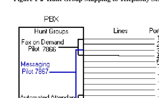
18 Chapter 1, OnePoint Messenger/SX-2000 Integration Overview Figure 1-2 Hunt Group Mapping to Telephony Server Ports
Figure 1-2 shows three overlapping hunt groups. Ports 3 and 4 take calls from both the Fax on Demand hunt group and the Messaging hunt group. Ports 11 and 12 take calls from both the Messaging hunt group and the Automated Attendant hunt group.
The Fax on Demand hunt group has four lines. Two of those lines connect to ports 1 and 2, which are assigned the Fax on Demand application. Any caller reaching those two ports is greeted by the Fax on Demand service greeting. On the other hand, because ports 3 and 4 are connected to lines that are in two hunt groups, Telephony Server must interpret the CLI data to determine which hunt group has called to determine which greeting to play. If Telephony Server determines that the called number is the Fax on Demand pilot, it runs the Fax on Demand application, and so forth.
In the example, Automated Attendant operation is similar to Fax on Demand, with its hunt group overlapping the numbers in the Messag-ing hunt group.
Notifications and SendFax are outbound applications that require out-dial ports on the PBX. Their lines are not included in the lines moni-tored by the call pickup box.
Required Skills 19
Table 2-22 (page 43) shows an alternative setup with Trunk 103 dedi-cated to the Automated Attendant, while Table 2-23 (page 44) shows Trunk 104 dedicated to Fax on Demand. Both of those services can also be provided by the Telephony Server application, depending on how OnePoint Messenger is set up, so your PBX technician needs to coordinate with the OnePoint Messenger installer to assure that the trunk allocations on the PBX match the Telephony Server setup and the preferences of your organization.
Required Skills
While OnePoint Messenger is designed to be relatively simple to implement and use, and the OnePoint Messenger guides detail the Windows NT and Exchange tasks needed to configure and manage a OnePoint Messenger environment, installers and administrators should not rely solely on this documentation. Integrating the
OnePoint Messenger Telephony Server with a Mitel PBX requires the skills of a Mitel-certified PBX technician and certification in the installation of OnePoint Messenger. Before entering training, OnePoint Messenger installers are expected to have Microsoft Certi-fied Systems Engineer (MCSE) certification in Windows NT Server 4.0 and Microsoft Exchange.
If you wish to provide user access to mailboxes using a Web browser, you must install and manage Microsoft’s Internet Information Server (IIS), which requires training equivalent to completion of the IIS course in the MCSE course series.
When installing and managing Windows NT and Exchange, you are required to perform NT administrator functions—setting up domains, creating administrator accounts, and performing software mainte-nance and backups. OnePoint Messenger applications use standard Windows interfaces and interoperate with NT system utilities.
How to Use This Guide
20 Chapter 1, OnePoint Messenger/SX-2000 Integration Overview
This manual lists the critical PBX features that must be enabled, but it does not detail the use of the PBX user interface. Also, this manual does not discuss the complete array of monitoring, programming, and troubleshooting options available to the installers and administrators of the Mitel PBX and of OnePoint Messenger. Becoming familiar with those options requires classroom training offered for both of those products.
For installing cards in the Telephony Server, refer to Chapter 3 as a summary, but to be sure you have all current information and details on options, see the manufacturers’ documentation, as listed in Appendix A of the OnePoint Messenger Installation Guide.
Sources of information on other supporting hardware and software are listed below in “Other Documentation”.
Organization of this Manual
This manual contains six chapters, an appendix, and an index:
• Chapter 1 introduces you to OnePoint Messenger and its docu-mentation.
• Chapter 2 (page 25) explains how to configure the SX-2000® LIGHT PBX to recognize the OnePoint Messenger Telephony Server.
• Chapter 3 (page 45) lists the hardware necessary to install on the Telephony Server to integrate with the SX-2000, and it summa-rizes the installation process.
• Chapter 4 (page 61) covers the installation of Mitel’s MiTAI 7.5.3 software on the Telephony Server.
• Chapter 5 (page 67) explains how to configure the OnePoint Messenger software on the Telephony Server that supports the PBX integration and telephony applications, such as Message Waiting, paging notification, and fax services.
• Chapter 6 (page 85) provides troubleshooting advice, including system validation tests. For more, see the OnePoint Messenger
Installation Guide and the OnePoint Messenger Administrator Guide.
Other Documentation 21
Other Documentation
The OnePoint Messenger documentation set includes:
• OnePoint Messenger Administrator Guide
• OnePoint Messenger Getting Started Guide
• OnePoint Messenger Installation Guide
• OnePoint Messenger User Guide
• OnePoint Messenger Quick Reference Card for the telephone
• Integration guides for PBXs: Fujitsu 9600, Lucent Definity, Mitel SX-200 and SX-2000, NEC 2400, and Nortel Meridian
The OnePoint Messenger Administrator Guide contains a system overview and administration details that can help you, the installer, understand the purposes and use of the components. It contains pro-cedures for creating user mailboxes (Chapter 2), configuring the Tele-phony User Interface (Chapter 3), managing fax services (Chapter 4), and operating and maintaining the Telephony Server (Chapter 5), as well as details on each OnePoint Messenger utility.
The OnePoint Messenger User Guide describes the use of OnePoint Messenger features—on Outlook, a Web browser, and the tele-phone—including the many fax features.
Other useful documentation includes Windows NT and Exchange manuals, as well as manuals covering the other Microsoft software that supports OnePoint Messenger. Contact information for Microsoft and for other vendors whose products complete your OnePoint Messenger unified messaging environment appears in Appendix B of the OnePoint Messenger Administrator Guide.
Using Electronic and Printed Versions
This guide uses a format that accommodates both on-screen viewing and printing. The text is aligned to 7" by 9" borders, so that, when printed on normal letter stock, there is a lot of room for you to make notes. Use Acrobat Reader version 3.0 or better to view and print PDF versions of the document.
22 Chapter 1, OnePoint Messenger/SX-2000 Integration Overview
Conventions Used in This Guide
Formatting conventions used in OnePoint Messenger guides give you extra cues about the action that you are to take.
Terms Used for Keys, Commands, and Buttons
The commands “select”, “clear”, “click”, and “choose” all mean basi-cally the same thing—to make a choice—but the terms are used in specific situations:
• “Choose” is used in menus, such as the Windows Start menu and program menus, to indicate menu items.
• “Click” is used for obvious buttons, up and down arrows, in edit boxes, spin controls, and for the Windows Start button.
• “Double-click” is used in any situation where pressing the mouse button twice is the most appropriate action, although other options may be available.
• “Press” is used when indicating a computer keyboard or tele-phone keypad key. There are brackets around the keyboard key, as in “Press [Tab].”
• “Select” is used on property pages (tabs) and dialogs, such as to indicate items in a field or group of options. “Clear” is used to deselect a check in a check box or an entry in a field.
This guide generally does not include the keyboard shortcuts for menus and commands. To use the keyboard shortcuts, you should:
• Display menus by pressing [Alt] and the underlined character dis-played on the screen (for example, press [Alt+F] for the File menu).
• Choose commands by typing the underlined character displayed on the screen (for example, press [S] for the Save command).
An instruction that involves making a choice from a menu is struc-tured: “From the XXX menu, choose YYY”. This style is also used for dialog boxes. As you become familiar with the style, you can focus on the words in bold as the critical operative phrases.
Images and Tables
Other Documentation 23
When presenting information about buttons, such as “Click the XXX button to open the YYY dialog box,” this guide might present the but-ton to the left of the instruction, as shown here. In that case, the graphic is not labelled.
Type Used in Commands and Screen Output
For statements in command syntax format, small mono-spaced type like this indicates the characters you should type. Brackets like these < > designate the variables that you are to replace with other information. For example, in the following command, you type the word INSTALL but replace “drive” and “directory” with the names of the drive and directory you are using:
<drive>\<directory>\INSTALL
The same font is used for presenting screen output.
List Styles
Numbered lists present the steps of procedures that you must follow in the order given.
Bulleted lists present options for which the order is not important.
Note and Caution Styles
A “NOTE:” presents information that is of special importance or is relevant only to some users or in some situations.
A “CAUTION!” alerts you to choices with potentially problematic results.
A “WARNING!” is more serious than a caution, alerting you to a choice that could cause a failure of the system.
Other Text Styles
Italic type is used to introduce terms and for the titles of publications.
24 Chapter 1, OnePoint Messenger/SX-2000 Integration Overview
Contacting Technical Publications
The Mitel Technical Publications and Media Development Group maintains this document. We welcome your questions and sugges-tions—notes on spelling and grammatical errors, comments on read-ability, and suggestions for improvements. Please reference the document number that appears on the back of the cover page. Address your comments to:
To check for the most current documentation:
1. Access the Mitel website:
http://www.mitel.com 2. Log on to Mitel Online.
3. Click Tech Support (in the top navigation bar).
OnePoint Messenger/SX-2000 Integration Guide, Issue 2, 12/14/00 25
2. Configuring the SX-2000 LIGHT
This chapter explains how to configure the SX-2000 LIGHT PBX to support the features of the OnePoint Messenger Telephony Server. It is divided into the following sections:
See also “Forms Checklist” on page 29, which provides links to most of the sections in the chapter.
NOTE: For configuring OnePoint Messenger with a Mitel SX-200, see the OnePoint Messenger/SX-200 Integration Guide.
OnePoint Messenger Requirements of the PBX
The OnePoint Messenger unified messaging system provides two general categories of features that need PBX support:
• Dialed services: Message Center, Automated Attendant, and Fax on Demand
• User services: call forwarding to voice mail, CLI, Call-Me/Meet-Me, DID fax, fax forwarding, and message notifications
Section Page
OnePoint Messenger Requirements of the PBX 25
PBX Programming Overview and Assumptions 27
Class of Service Options 31
System Options Assignment 32
Setting Up the AFC Card Connection 32
Trunk Programming 36
Programming Voice Mail Ports 39
Programming the Automated Attendant (Receptionist) 43
26 Chapter 2, Configuring the SX-2000 LIGHT
Dialed Services
The Message Center, Automated Attendant, and Fax on Demand can use the same or separate incoming lines and trunks. While the Message Center and Automated Attendant menus can route the caller to the other two dialed services, ideally, each should have its own pilot number and hunt group. You can also program dedicated exten-sions for the Automated Attendant and Fax on Demand that are per-manently routed to the Message Center pilot.
NOTE: The SX-2000 also provides an Automated Attendant as an optional feature.
User Services
Call Forwarding: Set up OnePoint Messenger user extensions to redirect calls to the Telephony Server that were intended for a OnePoint Messenger user station, but encountered one of these condi-tions: forward busy (user is already using the telephone), forward no answer (user does not answer the telephone), and forward all calls (user has forwarded an incoming call to voice mail, or has set the tele-phone to automatically forward all calls to voice mail).
Calling Line Information (CLI): The PBX must have a digital port set up and connected to the Telephony Server to carry the call infor-mation associated with the forwarded call. This enables the Tele-phony Server to invoke the appropriate call interface.
Call-Me/Meet-Me is a service that enables users to control message recording and playback from their desktops, while using their tele-phone as the microtele-phone and speaker. To provide long distance Call-Me/Meet-Me, the line assigned to the Telephony Server port that sup-ports Call-Me/Meet-Me must have long distance outdialing privi-leges. That line can be shared by the line that supports paging.
Fax support:
• Incoming faxes: OnePoint Messenger enables a user to receive faxes in his or her mailbox in two ways:
• The standard method is that fax senders simply call the user’s extension, then press 5 to deposit the fax in the mailbox.
• DID fax: You can give a user a second extension not con-nected to a physical set. The user would advertise the line as a dedicated fax line that callers could dial to send a fax to the user without the risk of having the user answer the fax call.
PBX Programming Overview and Assumptions 27 Message notifications: Notifications of incoming messages can be provided by Message Waiting Indicators (MWI) on users’ sets and by paging users’ pagers and offsite telephones. MWI lets users know when they have unplayed messages usually with a light, stutter tone, or display on the user’s phone.
To support MWI indicators, those user extensions must be enabled to receive MWI, including turning off MWI after the user plays the mes-sage. To support paging, an outdial line is required to the Telephony Server that allows long distance outdialing.
For the OnePoint Messenger installer, make a written record of the line numbers that you enable for OnePoint Messenger, their functions (Message Center, Message Waiting Indicator, etc.) and pilot numbers.
PBX Programming Overview and Assumptions
The examples shown in this chapter are intended to show the gramming of each stage individually. For example, voice mail pro-gramming is shown, followed by propro-gramming for the Automated Attendant, and so on. In reality, the Digit Modification and Class of Restriction (COR) groups, for example, could be the same. The trunk group used for voice mail, the Automated Attendant, and Fax on Demand could be the same if you do not want to separate the traffic. It is important to note, however, that, if the system is configured in this way, the link may be taken up with Fax on Demand, leaving no resources for voice mail, etc.
Not all of the values in the tables in this chapter are required exactly as shown to enable OnePoint Messenger. For example, as shown below in Table 2-1where the Trunk Group number matches its Trunk Service number to show the association between the two, which is not required.
28 Chapter 2, Configuring the SX-2000 LIGHT
how to answer the call. The following table shows how Show N Tel lines and assigned applications map to their attached PBX trunks:
Table 2-1 PBX Trunks Mapped to SNT Lines and Applications
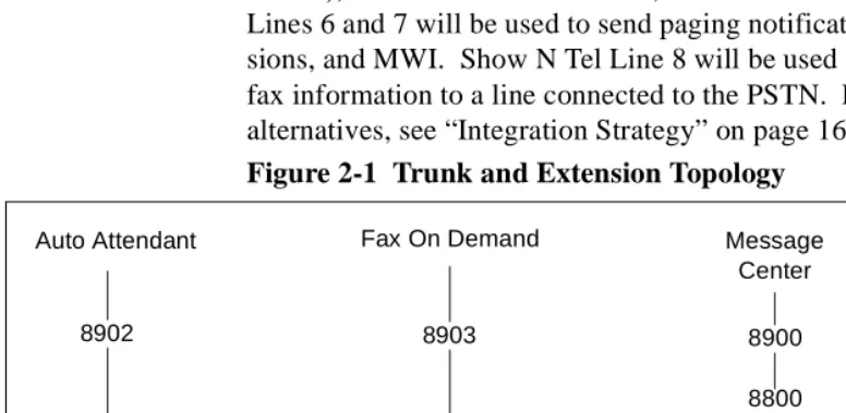
Using Table 2-1, Show N Tel Line 1 through Line 5 (Trunks 101 through 105) will be accessed by calls to voice mail (the Message Center), the Automated Attendant, or Fax on Demand. Show N Tel Lines 6 and 7 will be used to send paging notifications, Call-Me ses-sions, and MWI. Show N Tel Line 8 will be used only for sending fax information to a line connected to the PSTN. For more on setup alternatives, see “Integration Strategy” on page 16 in Chapter 1. Figure 2-1 Trunk and Extension Topology
Trunk Service Trunk Group Trunk SNT Line SNT Application
21 21 101 1 Telephony Server
21 21 102 2 Telephony Server
21 21 103 3 Telephony Server
21 21 104 4 Telephony Server
21 21 105 5 Telephony Server
22 22 106 6 Notification (Full)
22 22 107 7 Notification (Full)
23 23 108 8 Send Fax
Auto Attendant
ARS
Fax On Demand Message
Center
8900
8800
Trunk Group 21
Trunks 101-105
Pilot Number
Speed Call
8700
ARS Route 21
Actual Number 8903
Trunk Group 21
Trunks 101-105 8902
Trunk Group 21
Trunks 101-105
PBX Programming Overview and Assumptions 29
*CR Always: call rerouted always
Figure 2-1 shows how calls to the three pilot numbers are routed:
• The Message Center pilot is set up as an HCI Reroute—an auto-matic routing of the call through a speed dial number to an
Auto-matic Route Selection (ARS) Route number and then to the trunk
group (Trunk Group 21 in this example) set up to connect the Message Center lines to the Telephony Server.
• In this example, the Automated Attendant and Fax on Demand pilots are in the Message Center hunt group and use the same trunk group. They access the trunk group directly, and do not use the HCI Reroute facility.
This chapter details the entries you must make on the forms to enable the topology shown above, using the setup sequence shown in “Forms Checklist” on page 29.
An alternative topology, as described in “Integration Strategy” on page 16 in Chapter 1, is to dedicate lines to Automated Attendant and/or Fax on Demand. In that case, you would create separate trunk groups for those services. See “Programming the Automated Atten-dant (Receptionist)” on page 43 and “Programming Fax on Demand” on page 44. You might do this when you have more lines connected to the Telephony Server, or when you want to provide more assured access to one of those services.
You must also create trunk groups to provide outdial functionality, such as new-message notifications by paging and fax.
Directory Number 7999
Directory Number 7999 (DN 7999) provides a backup route for MWI, because the default timer turns off MWI lights after eight hours. You will create Class of Service 64 to be assigned to DN 7999 (see “Class of Service for Stations” on page 31), allocate DN 7999 in the Single Line Assignment Form (see “Creating Directory Number 7999” on page 39), then assign DN 7999 to the Message Center hunt group (see “Assigning a Hunt Group to the Message Center” on page 39). DN 7999 appears automatically on the Call Rerouting Assignment form.
Forms Checklist
30 Chapter 2, Configuring the SX-2000 LIGHT
OnePoint Messenger Telephony Server. The table sequence repre-sents a typical sequence in which you would edit the forms. This chapter follows that sequence, with a few exceptions, such as present-ing the Class of Service setup first.
Table 2-2 SX-2000 Forms Checklist
Forms See Page
PBX System Level Programming • Dimension and Feature Selection • Systems Options Assignment • Cabinet Assignment
• System Configuration
32 32 33 33
Digital Link Programming
• Digital Link Descriptor Assignment • Digital Link Assignment
34 36
Trunk Programming
• MSDN-DPNN-DASS-II Trunk Circuit Descriptor Assignment • Trunk Service Assignment
• Trunk Assignment • Trunk Group Assignment • Class of Service Assignment
36 37 37 38 31
Hunt Group Programming
• Hunt Group Assignment 39
HCI Reroute Programming
• System Speed Call Assignment • Call Reroute Assignment • Call Reroute Always Alternative • Route Assignment
• Automatic Route Selection Assignment • Digit Modification Assignment (Optional) • Class of Restriction Assignment (Optional)
40 41 41 42 42 not shown 43 Station Programming • DNI Assignment • Single Line Assignment • Class of Service Assignment • Call Rerouting First Alternative
• Call Rerouting Second Alternative (Optional)
Class of Service Options 31
Class of Service Options
Class of Service for Stations
Program the following Class of Service to be used for any client sta-tion using OnePoint Messenger.
Table 2-3 Class of Service Options Assignment, COS 10
Directory Number 7999: Create COS 64 with COV/ONS/E&M Voice Mail Port = Yes. You will later assign COS 64 to the Directory Number 7999.
Class of Service for Trunks
Program the Class of Service options shown in Table 2-4 for the digi-tal trunks on the CEPT card used to link the PBX with the Telephony Server.
Table 2-4 Class of Service Options Assignment, COS 21
* ANI/DNIS/ISDN Number Delivery Trunk can only be set to "Yes" if the option was purchased. If Dim and Feature are set to "No", the COS option cannot be "Yes" in the Trunks COS.
Class of Service Options Assignment
Class of Service number: 10
Option Select
HCI/CTI/TAPI Call Control Allowed Yes
HCI/CTI/TAPI Monitor Allowed Yes
Public Network Access via DPNSS Yes
Class of Service Options Assignment
Class of Service number: 21
Option Select
* ANI/DNIS/ISDN Number Delivery Trunk Yes
HCI/CTI/TAPI Call Control Allowed Yes
HCI/CTI/TAPI Monitor Allowed Yes
32 Chapter 2, Configuring the SX-2000 LIGHT
System Options Assignment
On the System Options Assignment form, set the values shown here.
Table 2-5 System Options Assignment
For SUPERSET Callback Message Cancel Timer, enter a number in the range of “1” to “255” hours, in increments of 1 hour. This value defines the length of time for which a callback message will be displayed on a telephone's LCD display. If this field is left blank the message will not be cancelled.
NOTE: If the “SUPERSET” option has any value, it cancels all call-back messages on the system that were set by the Telephony Server.
Setting Up the AFC Card Connection
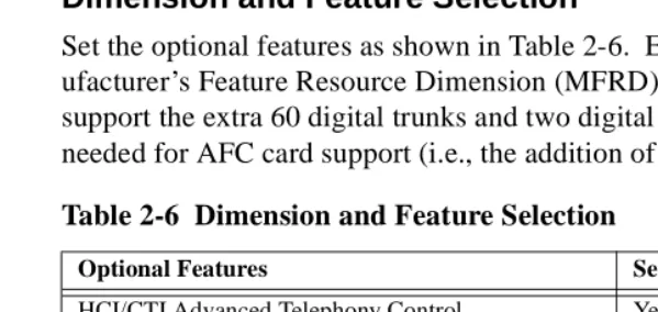
Dimension and Feature Selection
Set the optional features as shown in Table 2-6. Ensure that the Man-ufacturer’s Feature Resource Dimension (MFRD) is large enough to support the extra 60 digital trunks and two digital links that will be needed for AFC card support (i.e., the addition of a CEPT card).
Option Value
DTRX Herald Message (Enter Line Below, 0-77 chars.)
Maximum Parties In A Conference (3-8, max. 5 on the MCS)
Maximum Trunks In A Conference (0-8) 8
Music On Hold (Yes/No) Yes
SUPERSET Callback Message Cancel Timer (1-255 hrs) (see next)
Blank recommended *see note
Table 2-6 Dimension and Feature Selection
Optional Features Settings
HCI/CTI Advanced Telephony Control Yes
HCI/CTI Basic Telephony Control Yes
MSDN/DPNSS Public Network Access Yes
MSDN/DPNSS Voice I Yes
*MSDN/DPNSS Voice III Yes
*MSDN/DPNSS Voice V Yes
System Configuration Selection
Setting Up the AFC Card Connection 33
* Voice III and V are optional ONLY if using networked voice mail. The HCI Large Traffic Level must be a minimum of 1 (100 moni-tors). This field determines the HCI monitors allowed in the PBX.
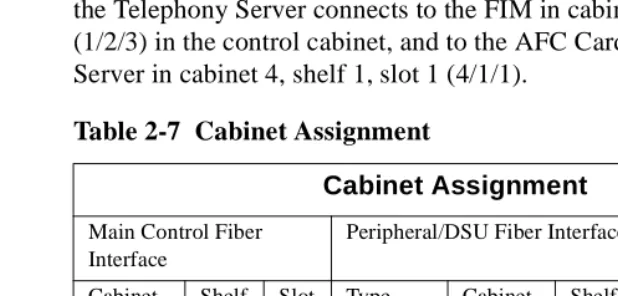
Cabinet Assignment
WARNING! Adding a cabinet to an operating PBX will cause peripherals to reset.
The Cabinet Assignment form applies to fiber distributed systems. It tells the main control cabinet what types of cabinets are at the ends of the fiber links. The form identifies each fiber link by the FIM to which it connects at each end. It specifies each FIM by cabinet, shelf, and slot (PLID).
The OnePoint Messenger Telephony Server registers as a fiber dis-tributed digital service unit (FD_DSU) cabinet type. Add the Tele-phony Server in cabinet "X", shelf 1, slot 1 (where "X" is a free cabinet number within your PBX). In this sample table, fiber going to the Telephony Server connects to the FIM in cabinet 1, shelf 2, slot 3 (1/2/3) in the control cabinet, and to the AFC Card in the Telephony Server in cabinet 4, shelf 1, slot 1 (4/1/1).
System Configuration
The System Configuration form records the position of all printed cir-cuit cards in the system. The Cabinet, Shelf, Slot, and Installed Card Type fields are read-only. Refer to Table 2-8.
1. Verify that the FIM card is programmed and installed in the PBX system. If the FIM is not installed, refer to SX-2000 LIGHT PBX documentation for instructions on how to install it.
Table 2-7 Cabinet Assignment
Cabinet Assignment
Main Control Fiber Interface
Peripheral/DSU Fiber Interface
Cabinet Shelf Slot Type Cabinet Shelf Slot Comments
1 2 1 FD_Per 2 1 17 Internal Per
1 2 2 FD_DSU 3 1 1 Internal
DSU
1 2 3 FD_DSU 4 1 1 Telephony
Server
34 Chapter 2, Configuring the SX-2000 LIGHT
2. Enter “CEPT Formatter” in the Programmed Card Type field in Shelf 1 in slot 2 or 3.
NOTE: The card location in the table is an example only. Actual locations in the customer installation may vary.
The CEPT Formatter will not show as installed until the AFC card in the Telephony Server is loaded.
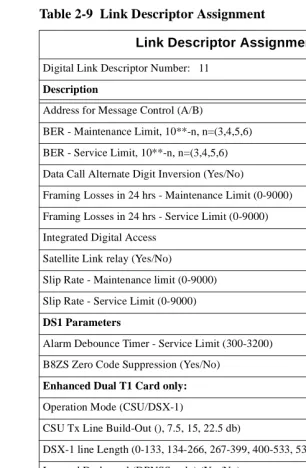
Digital Link Descriptor Assignment
Link descriptor programming is required for digital link emulation for the AFC B-channels. As shown in Table 2-9, use default parameters for all fields except:
• Address for Message Control (A/B) = A
• Integrated Digital Access = CTI Server Table 2-8 System Configuration
System Configuration
Cabinet Shelf Slot Programmed Card Type
Installed Card Type
4 1 1 Fiber Interface Fiber Interface
4 1 2 CEPT Formatter CEPT Formatter
4 1 3 No Card Present No Card Present
4 1 4 No Card Present No Card Present
4 1 5 No Card Present No Card Present
4 1 6 No Card Present No Card Present
4 2 1 Peripheral Resource Peripheral Resource
4 2 2 No Card Present No Card Present
4 2 3 No Card Present No Card Present
4 2 4 No Card Present No Card Present
4 2 5 No Card Present No Card Present
Setting Up the AFC Card Connection 35 Table 2-9 Link Descriptor Assignment
Link Descriptor Assignment
Digital Link Descriptor Number: 11
Description Value
Address for Message Control (A/B) A
BER - Maintenance Limit, 10**-n, n=(3,4,5,6) 4
BER - Service Limit, 10**-n, n=(3,4,5,6) 3
Data Call Alternate Digit Inversion (Yes/No) Yes
Framing Losses in 24 hrs - Maintenance Limit (0-9000) 255
Framing Losses in 24 hrs - Service Limit (0-9000) 9000
Integrated Digital Access CTI Server
Satellite Link relay (Yes/No) No
Slip Rate - Maintenance limit (0-9000) 255
Slip Rate - Service Limit (0-9000) 7000
DS1 Parameters
Alarm Debounce Timer - Service Limit (300-3200) 500
B8ZS Zero Code Suppression (Yes/No) Yes
Enhanced Dual T1 Card only:
Operation Mode (CSU/DSX-1) DSX-1
CSU Tx Line Build-Out (), 7.5, 15, 22.5 db)
DSX-1 line Length (0-133, 134-266, 267-399, 400-533, 534-655 ft.) 0-133
Inverted D-channel (DPNSS only) (Yes/No) No
El Parameters (Enhanced Dual E1 Card only):
CRC-4 enabled (Yes/No) No
E1 Line Length (0-133, 134-266, 267-399, 400-533, 534-655 ft). 0-133
Italian Parameters
36 Chapter 2, Configuring the SX-2000 LIGHT
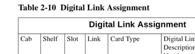
Digital Link Assignment
Use the Digital Link Assignment form to identify the digital link descriptor that is associated with the CEPT card programmed in the previous section.
Trunk Programming
MSDN/DPNSS/DASSII Trunk Circuit Descriptor
Assignment
With a CEPT card programmed in the PBX, 60 digital trunks will be available in the Trunk Assignment form. A circuit descriptor must now be programmed for the digital trunks before the Trunk Assign-ment form can be completed. Choose a free circuit descriptor. Leave the default settings, except for changing Far End Connection (Main PBX/Satellite PBX/Toll/Local) to Local Office.
Table 2-10 Digital Link Assignment
Digital Link Assignment
Cab Shelf Slot Link Card Type Digital Link Description Number
Text
4 1 2 1 CEPT Formatter 11 Telephony Serv
4 1 2 2 CEPT Formatter 11 Telephony Serv
Table 2-11 MSDN-DPNSS-DASSII Trunk Circuit Descriptor Assignment
MSDN/DPNSS/DASSII Trunk Circuit Descriptor Assignment
Trunk Circuit Descriptor Number: 11
Description Value
Signalling Protocol f(MSDN-DPNSS/DASSII) MSDN-DPNSS
Card Type (CEPT/DS1/PR1/E1/PRI T1) CEPT
Dual Seizure Priority (Incoming/Outgoing) Incoming
ISDN BRI Mode (blank/NT/LT)
Transmission Parameters
Trunk Programming 37
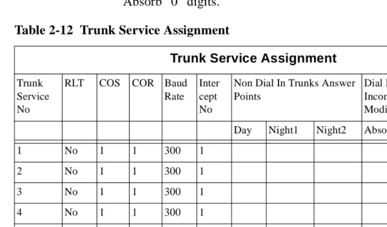
Trunk Service Assignment
In the Trunk Service Assignment form, create Trunk Service Assign-ment entries for the digital trunks connecting the Telephony Server to the PBX—"Tel Serv" (serves Message Center, Automated Attendant, and Fax on Demand), MWI (serves both notifications and Call-Me), and Fax Send. Enter the trunk Class of Service (COS) (see “Class of Service for Trunks” on page 31) and Class of Restriction (COR). Absorb “0” digits.
Trunk Assignment
The Trunk Assignment form assigns trunk numbers to the trunk cir-cuits of the AFC’s digital links. Enter the Trunk Circuit Descriptor number and the Trunk Service number obtained from the Trunk Ser-vice Assignment form. Leave the DTS SerSer-vice Number field blank. The Circuit Descriptor Number is obtained from the MSDN-DPNSS-DASSII Trunk Circuit Descriptor Assignment form (Table 2-11). Table 2-12 Trunk Service Assignment
Trunk Service Assignment
Trunk Service No
RLT COS COR Baud Rate
Inter cept No
Non Dial In Trunks Answer Points
Dial In Trunks Incoming Digit Modification
Trunk Label
Day Night1 Night2 Absorb Insert
1 No 1 1 300 1
2 No 1 1 300 1
3 No 1 1 300 1
4 No 1 1 300 1
21 No 21 1 300 1 0 Tel
Serv
22 No 21 1 300 1 0 MWI
23 No 21 1 300 1 0 Fax
38 Chapter 2, Configuring the SX-2000 LIGHT
.
NOTE: This example shows only eight trunks. The HCI link sup-ports up to 60 such trunks, but the number of trunks required depends on the number of channels available on the NMS cards on the OnePoint Messenger Telephony Server. For example, if an 8-port NMS card is used on the Telephony Server, eight trunks must be pro-grammed on the PBX. These eight trunks will be allocated to a DSP on the NMS Card. For 16 ports, 16 trunks are required, and so on.
Give the trunk numbers to the OnePoint Messenger installer. They must be entered in the Device Map tab of Show N Tel, as described in “Configuring Show N Tel with a PBX” on page 68 in Chapter 5.
Assigning Trunk Groups to the Message Center
As shown in Table 2-14, set up a trunk group containing the trunks that will be allocated to the OnePoint Messenger Telephony Server application, used primarily for the Message Center, but also, in this example, Automated Attendant and Fax on Demand. See also “Pro-gramming the Automated Attendant (Receptionist)” on page 43 and “Programming Fax on Demand” on page 44. For details, see “PBX Programming Overview and Assumptions” on page 27.
NOTE: Hunt mode can be set up as Terminal (always take the first trunk unless it is busy), or Circular (use the first trunk, then the sec-Table 2-13 Trunk Assignment
Trunk Assignment
Cab Shlf Slot Circ Card Type Trunk Number
Trunk Service Number
DTS Service Number
Circuit Desc Number
Inter-Connect Number
4 1 2 1 CEPT Formatter 101 21 11 1
4 1 2 2 CEPT Formatter 102 21 11 1
4 1 2 3 CEPT Formatter 103 21 11 1
4 1 2 4 CEPT Formatter 104 21 11 1
4 1 2 5 CEPT Formatter 105 21 11 1
4 1 2 61 CEPT Formatter 106 22 11 1
4 1 2 7 CEPT Formatter 107 22 11 1
Programming Voice Mail Ports 39
ond, and so on); Circular is best, but not necessary, for OnePoint Messenger.
Creating Directory Number 7999
Using the same Circuit Descriptor (11 in this example) that you use to provide the trunks for OnePoint Messenger, create another line item in the Single Line Assignment Form to create Directory Number 7999 (enter 7999 in the Directory Number column).
In the Station Service Assignment Form, for 7999, enter 64 in the three COS fields, Day, Night 1, and Night 2.
Programming Voice Mail Ports
Assigning a Hunt Group to the Message Center
Set up a hunt group with a pilot number for the Message Center. Select the group type as HCI Reroute. This hunt group contains no members and will be rerouted to a speed call and then to an ARS route. This is necessary, because it is not possible to route unan-swered calls directly to the pilot number of the OnePoint Messenger Message Center.
The OnePoint Messenger installer must enter this pilot number in:
• The MWIPilotNumber field in TelSrvr.ini, located in the c:\SNT\TelSrvr directory (see “Editing the Telsrvr.ini File” on page 80 in Chapter 5).
Table 2-14 Trunk Group Assignment
Trunk Group Assignment
Trunk Group Number: 21
Hunt Mode (Circular or Terminal): Circular Trunk Group Busy RAD:
Maximum Network Hops:
Number Trunk Number
1 101
2 102
3 103
4 104
40 Chapter 2, Configuring the SX-2000 LIGHT
• The Pilot Number field of the Message Center page in the Uni-fied Messaging Snap-in to Microsoft Management Console (see “Setting Telephone User Interface Parameters” on page 78 in Chapter 5; for details, see Chapter 3 in the OnePoint Messenger
Administrator Guide.)
System Speed Call Assignment
Configure a System Speed Call, as shown on Table 2-16, that will dial the external ARS route that you have just set up to the Telephony Server. The Speed Call will be referenced as the answer point for a Call Reroute Always from the HCI Reroute Number.
OnePoint Messenger users will call-forward their phones to this num-ber so that callers will access those users’ mailboxes.
• Overrides Toll Control = Yes
• Type = Int
Table 2-16 System Speed Call Assignment Table 2-15 Hunt Group Assignment
Hunt Group Assignment
Pilot Number: 8900 Hunt Mode: Terminal Group Type: HCIReroute RAD1:
RAD2: NIGHT RAD:
Name: ONEPOINT PILOT Priority: 64
1st Threshold (%): 2nd Threshold (%): Alert Device: Phase Timer:
Member Directory
Number
Name
7999
System Speed Call Assignment
Speed Call Number
Actual Number Overrides Toll Control
Type
Programming Voice Mail Ports 41
Call Reroute Assignment
Configure the entry for the HCI Reroute Hunt Group number to an Always Alternative number that is not being used.
In this form we are telling the PBX to always reroute any call that goes to the Directory Number 8900 (Message Center pilot) to an Always Alternative Number (an index number).
NOTE: Do not use Reroute 1.
Table 2-17 Call Rerouting Assignment
Call Reroute Always Alternative Assignment
Using the Always Alternative number configured for the HCI Route Hunt Group, reroute calls from every type of originating device to the Speed Call number that you have set up.
Table 2-18 Call Rerouting Always Alternative Assignment Call Rerouting Assignment
Always Alternative Number
Number Day Number Night 1
Number Night 2
Do Not Disturb Type
First Alternative Number
Second Alternative Number
8900 21 21 21 All 1 1
Call Rerouting Always Alternative Assignment
Always Originating Device
Always Alternative Number
DID TIE CO Internal Directory
Number Routed To
42 Chapter 2, Configuring the SX-2000 LIGHT
Automatic Route Selection (ARS) Assignment
Set up an ARS route with the following values (as per the example):
• Leading Digits = 8
• Digits Dialed = 700
• Number of Digits to Follow = 0
• Type = Route
• Number = <X> (where X is the Route number set up in the previ-ous step).
This sets up an ARS route to the Telephony Server via the digital trunks. The route is referenced in a System Speed Call Assignment.
Table 2-19 Automatic Route Selection Assignment
Route Assignment
Set up a route that references the trunk group containing the trunks that will be allocated to voice mail resources on the NMS card. Ref-erence the default COR Group and Digit Modification number.
Table 2-20 Route Assignment
Automatic Route Selection Assignment
Leading Digits: 8
Second Dial Tone (Yes/No/Alternate): No COR Group Number:
Termination
Digits Dialed Number of Digits to Follow
Type Number
700 0 Route 21
Route Assignment
Route Number
Trunk Group Number
COR Group Digit Modification Number
Digits Before Outpulsing
Programming the Automated Attendant (Receptionist) 43
Class of Restriction (COR) Group Assignment
Set up a COR group that contains no CORs.
Table 2-21 Class of Restriction Group Assignment
Programming the Automated Attendant (Receptionist)
In the example topology detailed above, Automated Attendant has its own pilot number, 8902, which uses the same trunk group as the Mes-sage Center, Trunk Group 21. If you want to dedicate one or more lines to Automated Attendant, you would follow the same sequence as used above to provision the trunk group and hunt group. Do not create and HCI Reroute. In the example in Table 2-22, a new Trunk Group 24 has one member, Trunk 103, which you would remove from Trunk Group 21.
Table 2-22 Trunk Group Assignment for Automated Attendant Class of Restriction Group Assignment
COR Group Number
Classes of Restriction for Group
1
Trunk Group Assignment Trunk Group Number: 24
Hunt Mode (Circular or Terminal): Circular Trunk Group Busy RAD:
Maximum Network Hops:
Member Trunk Number
44 Chapter 2, Configuring the SX-2000 LIGHT
Programming Fax on Demand
In our original example, Fax on Demand has its own pilot number, 8903, but it uses the same Trunk Group 21 as the Message Center and the Automated Attendant. To associate that pilot its own hunt group and trunk group, you would follow the same sequence as described above for the dedicated Automated Attendant line. In the example in Table 2-23, a new Trunk Group 25 has one member, Trunk 104, which you would remove from Trunk Group 21.
Table 2-23 Trunk Group Assignment for Fax on Demand
Trunk Group Assignment
Trunk Group Number: 25
Hunt Mode (Circular or Terminal): Circular Trunk Group Busy RAD:
Maximum Network Hops:
Member Trunk Number
OnePoint Messenger/SX-2000 Integration Guide, Issue 2, 12/14/00 45
3. Installing Line Cards in the
Telephony Server
This chapter discusses the Telephony Server line cards necessary to integrate OnePoint Messenger with the Mitel SX-2000, and it sum-marizes the installation process. For the turnkey TS800, the cards should have all been installed at the factory, but you can refer to this chapter if you need to change the configuration, such as when you add a card or upgrade to a new server. This chapter contains installa-tion summaries; for details, see Appendix B in the OnePoint
Messen-ger Installation Guide, then see the manufacturers’ documentation.
This chapter contains these sections:
What Hardware Do You Need on the Telephony Server?
The cards that have been validated for the SX-2000 integration are:
• Mitel: Application Fiber Controller (AFC) TAPI card: The AFC provides call processing through a fiber connection to the Fiber Interface Module (FIM) on the SX-2000. Use an MVIP cable to connect the AFC with either NMS AG-0 or AG-24 cards to
Section Page
What Hardware Do You Need on the Telephony Server?
45
Preparing the Installation Site 47
Setting Up MVIP Arrays 48
Setting Interrupts and Base Addresses 49
Installing Brooktrout Fax Cards 51
Installing and Configuring an NMS Card 52
Enabling the Mitel AFC Card with MiTAI 57
46 Chapter 3, Installing Line Cards in the Telephony Server
provide DSP resources. You can also connect one or more Brooktrout fax cards through the MVIP cable.
• Natural MicroSystem (NMS) Alliance Generation (AG) ISA AG-0 (8 ports) and AG-24 (24 ports) DSP resource cards: Use these cards as DSP voice processing resources for the Mitel AFC card. The AG-0 is an AG-8 with the SIPPs removed (used for line control).
• Brooktrout: The following Brooktrout Technology fax boards: • TR114+ I4V/I8V (4- and 8-port MVIP)
• TR114+ I4L (4-port)
Connect one or more of these boards with the line cards through an MVIP cable, as described below.
Fiber Optic Cable Specifications
If you use a Mitel AFC card in the Telephony Server, you will need fiber link cables for the link between the Telephony Server and the SX-2000. Two cables are required for a link, one for transmitting (connect to the TX connection on the PBX and the RX connection on the AFC card) and the other for receiving (lights on the AFC card will flash if you have the wires crossed.)
• Fiber Cable Type: Glass Multi-mode
• Fiber Diameter: 62.5/125 mm
• Connector Type: ST
• Maximum Distance (Cable Length): 1 km
• Maximum Optical Loss: 6 dB (including splices and connections)
• The grade or type of cable used must be suitable for the installa-tion (i.e., light or heavy duty, plenum, outdoor). Consult local building codes and your fiber cable supplier.