A Critical Study on a New Efficient Packet Classification
Deterministic Algorithm Using Boundary Cutting for Improved
Search Performance and Efficient Memory Management
Yeedi Venkata Tapaswini
1; B.Madhav Rao
2& Prof.Dr.G.Manoj Someswar
31
M.Tech.(CSE) from Narasimha Reddy Engineering College, Affiliated to JNTUH, Hyderabad, Telangana,
India
2
M.Tech. (CSE), Assistant Professor, Department of CSE, Narasimha Reddy Engineering College,
Affiliated to JNTUH, Hyderabad, Telangana, India
3
B.Tech., M.S.(USA), M.C.A., Ph.D., Principal & Professor, Department Of CSE, Anwar-ul-uloom
College of Engineering & Technology, Affiliated to JNTUH, Vikarabad, Telangana, India
ABSTRACT:
Decision-tree-based packet classification algorithms such as HiCuts, HyperCuts, and EffiCuts show
excellent search performance by exploiting the geometrical representation of rules in a classifier and
searching for a geometric subspace to which each input packet belongs. However, decision tree algorithms
involve complicated heuristics for determining the field and number of cuts. Moreover, fixed interval-based
cutting not relating to the actual space that each rule covers is ineffective and results in a huge storage
requirement. A new efficient packet classification algorithm using boundary cutting is proposed in this
paper. The proposed algorithm finds out the space that each rule covers and performs the cutting
according to the space boundary. Hence, the cutting in the proposed algorithm is deterministic rather than
involving the complicated heuristics, and it is more effective in providing improved search performance
and more efficient in memory requirement. For rule sets with 1000–100 000 rules, simulation results show
that the proposed boundary cutting algorithm provides a packet classification through 10–23 on-chip
memory accesses and 1–4 off-chip memory accesses in average.
KEYWORDS: Mean time between failures (MTBF); Set Splitting Algorithm (SSA); Ternary Content
Addressable Memories (TCAMs); Multi match Using Discriminators (MUD); Network Intrusion Detection
System (NIDS).
INTRODUCTION What is networking?
Networking is the word basically relating to computers and their connectivity. It is very often used in the world of computers and their use in different connections. The term networking implies the link between two or more computers and their devices, with the vital purpose of sharing the data stored in the computers, with each other. The networks between the computing devices are very common these days due to the launch of various hardware and computer software
which aid in making the activity much more convenient to build and use.[1]
FIGURE 1: Structure of Networking between the
Conference Chair:Prof.Dr.G.ManojSomeswar, Director General, Global Research Academy, Hyderabad,
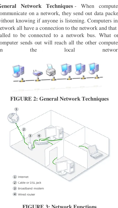
General Network Techniques - When computers
communicate on a network, they send out data packets without knowing if anyone is listening. Computers in a network all have a connection to the network and that is called to be connected to a network bus. What one computer sends out will reach all the other computers
on the local network.
FIGURE 2: General Network Techniques
FIGURE 3: Network Functions
Above diagrams show the clear idea about the networking functions
For the different computers to be able to distinguish between each other, every computer has a unique ID called MAC-address (Media Access Control Address).[2] This address is not only unique on your network but unique for all devices that can be hooked up to a network. The MAC-address is tied to the hardware and has nothing to do with IP-addresses. Since all computers on the network receives everything that is sent out from all other computers the
MAC-addresses is primarily used by the computers to filter out incoming network traffic that is addressed to the individual computer.
When a computer communicates with another computer on the network, it sends out both the other computers MAC-address and the MAC-address of its own. In that way the receiving computer will not only recognize that this packet is for me but also, who sent this data packet so a return response can be sent to the sender.[3]
On an Ethernet network as described here, all
computers hear all network traffic since they are connected to the same bus. This network structure is called multi-drop.
One problem with this network structure is that when you have, let say ten (10) computers on a network and they communicate frequently and due to that they sends out there data packets randomly, collisions occur when two or more computers sends data at the same time. When that happens data gets corrupted and has to be resent. On a network that is heavy loaded even the resent packets collide with other packets and have to be resent again. In reality this soon becomes a bandwidth problem. If several computers communicate with each other at high speed they may not be able to utilize more than 25% of the total network bandwidth since the rest of the bandwidth is used for resending previously corrupted packets. The way to minimize this problem is to use network switches.[4]
Characteristics of Networking:
The following characteristics should be considered in network design and ongoing maintenance:
1) Availability is typically measured in a
percentage based on the number of minutes that exist in a year. Therefore, uptime would be the number of minutes the network is available divided by the number of minutes in a year.
2) Cost includes the cost of the network
3) Reliability defines the reliability of the network components and the connectivity between them. Mean time between failures (MTBF) is commonly used to measure reliability.
4) Security includes the protection of the network
components and the data they contain and/or the data transmitted between them.
5) Speed includes how fast data is transmitted
between network end points (the data rate).
6) Scalability defines how well the network can adapt to new growth, including new users, applications, and network components.
7) Topology describes the physical cabling layout
and the logical way data moves between components.[5]
Types of Networks:
Organizations of different structures, sizes, and budgets need different types of networks. Networks can be divided into one of two categories:
peer-to-peer
server-based networks
1. Peer-to-Peer Network:
A peer-to-peer network has no dedicated servers; instead, a number of workstations are connected together for the purpose of sharing information or devices. Peer-to-peer networks are designed to satisfy the networking needs of home networks or of small companies that do not want to spend a lot of money on a dedicated server but still want to have the capability to share information or devices like in school, college, cyber café[6]
2. Server-Based Networks:
In server-based network data files that will be used by all of the users are stored on the one server. With a server-based network, the network server stores a list of users who may use network resources and usually holds
the resources as well.
This will help by giving you a central point to set up permissions on the data files, and it will give you a
central point from which to back up all of the data in case data loss should occur.
Network Communications:
Computer networks use signals to transmit
data, and protocols are the languages computers use to communicate.
Protocols provide a variety of communications services to the computers on the network.
Local area networks connect computers using a
shared, half-duplex, baseband medium, and wide area networks link distant networks.
Enterprise networks often consist of clients and
servers on horizontal segments connected by a common backbone, while peer-to-peer networks consist of a small number of computers on a single LAN.[7]
Advantages of Networking:
1. Easy Communication:
It is very easy to communicate through a network. People can communicate efficiently using a network with a group of people. They can enjoy the benefit of
emails, instant messaging, telephony, video
conferencing, chat rooms, etc.
2. Ability to Share Files, Data and Information:
This is one of the major advantages of networking computers. People can find and share information and data because of networking. This is beneficial for large organizations to maintain their data in an organized manner and facilitate access for desired people.
3. Sharing Hardware:
Another important advantage of networking is the ability to share hardware. For an example, a printer can be shared among the users in a network so that there’s no need to have individual printers for each and every computer in the company. This will significantly reduce the cost of purchasing hardware.
4. Sharing Software:
Conference Chair:Prof.Dr.G.ManojSomeswar, Director General, Global Research Academy, Hyderabad,
version of the same software. Therefore large companies can reduce the cost of buying software by networking their computers.
5. Security:
Sensitive files and programs on a network can be password protected. Then those files can only be accessed by the authorized users. This is another important advantage of networking when there are concerns about security issues. Also each and every user has their own set of privileges to prevent those accessing restricted files and programs.
6. Speed:
Sharing and transferring files within networks is very rapid, depending on the type of network. This will save time while maintaining the integrity of files.[8]
LITERATURE SURVEY
Packet classification is the core mechanism that enables many networking services on the Internet such as firewall packet filtering and traffic accounting. Using ternary content addressable memories (TCAMs) to perform high-speed packet classification has become the de facto standard in industry. TCAMs classify packets in constant time by comparing a packet with all classification rules of ternary encoding in parallel. Despite their high speed, TCAMs suffer from the
well-known range expansion problem. As packet
classification rules usually have fields specified as ranges, converting such rules to TCAM-compatible rules may result in an explosive increase in the number of rules. This is not a problem if TCAMs have large capacities.[9] Unfortunately, TCAMs have very limited
capacity, and more rules mean more power
consumption and more heat generation for TCAMs. Even worse, the number of rules in packet classifiers has been increasing rapidly with the growing number of services deployed on the Internet. In this paper, we consider the following problem: given a packet classifier, how can we generate another semantically equivalent packet classifier that requires the least number of TCAM entries? In this paper, we propose a
systematic approach, the TCAM Razor, that is effective, efficient, and practical. In terms of effectiveness, TCAM Razor achieves a total compression ratio of 29.0%, which is significantly better than the previously published best result of 54%. In terms of efficiency, our TCAM Razor prototype runs in seconds, even for large packet classifiers. Finally, in terms of practicality, our TCAM Razor approach can be easily deployed as it does not require any modification to existing packet classification systems, unlike many previous range encoding schemes.[10]
Several range reencoding schemes have been proposed to mitigate the effect of range expansion and the limitations of small capacity, large power consumption, and high heat generation of ternary content addressable memory (TCAM)-based packet classification systems. However, they all disregard the semantics of classifiers and therefore miss significant opportunities for space compression. In this paper, we propose new approaches to range re encoding by taking into account classifier semantics. Fundamentally different from prior work, we view re encoding as a topological transformation process from one colored hyper rectangle to another, where the color is the decision associated with a given packet. Stated another way, we re encode the entire classifier by considering the classifier's decisions rather than re encode only ranges in the classifier ignoring the classifier's decisions as prior work does. We present
two orthogonal, yet composable, reencoding
Today's packet classification systems are designed to provide the highest priority matching result, e.g., the longest prefix match, even if a packet matches multiple
classification rules. However, new network
applications, such as intrusion detection systems, require information about all the matching results. We call this the multi-match classification problem. In several complex network applications, multi-match classification is immediately followed by other processing dependent on the classification results. Therefore, classification should be even faster than the line rate. Pure software solutions cannot be used due to their slow speeds. We present a solution based on ternary content addressable memory (TCAM), which produces multi-match classification results with only one TCAM lookup and one SRAM lookup per packet - about ten times fewer memory lookups than a pure software approach. In addition, we present a scheme to remove the negation format in rule sets, which can save up to 95% of TCAM space compared with the straight forward solution. We show that using our pre-processing scheme, header pre-processing for the SNORT rule set can be done with one TCAM and one SRAM lookup using a 135 KB TCAM.[12]
New network applications like intrusion detection
systems and packet-level accounting require
multimatch packet classification, where all matching filters need to be reported. Ternary content addressable memories (TCAMs) have been adopted to solve the multimatch classification problem due to their ability to perform fast parallel matching. However, TCAMs are expensive and consume large amounts of power. None of the previously published multimatch classification schemes are both memory and power efficient. In this paper, we develop a novel scheme that meets both requirements by using a new set splitting algorithm (SSA). The main idea behind SSA is that it splits filters into multiple groups and performs separate TCAM lookups into these groups. It guarantees the removal of at least 1/2 the intersections when a filter set is split into
two sets, thus resulting in low TCAM memory usage. SSA also accesses filters in the TCAM only once per packet, leading to low-power consumption. We compare SSA with two best known schemes:
multimatch using discriminators (MUD)
(Lakshminarayanan and Rangarajan, 2005) and geometric intersection-based solutions (Yu and Katz, 2004). Simulation results based on the SNORT filter sets show that SSA uses approximately the same amount of TCAM memory as MUD, but yields a 75%-95% reduction in power consumption. Compared with geometric intersection-based solutions, SSA uses 90% less TCAM memory and power at the cost of one additional TCAM lookup per packet. We also show that SSA can be combined with SRAM/TCAM hybrid approaches to further reduce energy consumption[13] Using FPGA technology for real-time network intrusion detection has gained many research efforts recently. In this paper, a novel packet classification architecture called BV-TCAM is presented, which is implemented for an FPGA-based Network Intrusion Detection System
Conference Chair:Prof.Dr.G.ManojSomeswar, Director General, Global Research Academy, Hyderabad,
SYSTEM STUDY FEASIBILITY STUDY
The feasibility of the project is analyzed in this phase and business proposal is put forth with a very general plan for the project and some cost estimates. During system analysis the feasibility study of the proposed system is to be carried out. This is to ensure that the proposed system is not a burden to the company. For feasibility analysis, some understanding of the major requirements for the system is essential. Three key considerations involved in the feasibility analysis are
ECONOMICAL FEASIBILITY
TECHNICAL FEASIBILITY
SOCIAL FEASIBILITY
ECONOMICAL FEASIBILITY
This study is carried out to check the economic impact that the system will have on the organization. The amount of fund that the company can pour into the research and development of the system is limited. The expenditures must be justified. Thus the developed system as well within the budget and this was achieved because most of the technologies used are freely available. Only the customized products had to be purchased.
TECHNICAL FEASIBILITY
This study is carried out to check the technical feasibility, that is, the technical requirements of the system. Any system developed must not have a high demand on the available technical resources. This will lead to high demands on the available technical resources. This will lead to high demands being placed on the client. The developed system must have a modest requirement, as only minimal or null changes are required for implementing this system.
SOCIAL FEASIBILITY
The aspect of study is to check the level of acceptance of the system by the user. This includes the process of training the user to use the system efficiently. The user must not feel threatened by the
system, instead must accept it as a necessity. The level of acceptance by the users solely depends on the methods that are employed to educate the user about the system and to make him familiar with it. His level of confidence must be raised so that he is also able to make some constructive criticism, which is welcomed, as he is the final user of the system.
SYSTEM DESIGN
SYSTEM ARCHITECTURE:
FIGURE 4: System Architecture DATA FLOW DIAGRAM:
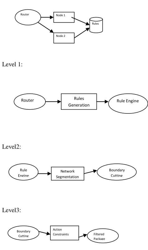
1. The DFD is also called as bubble chart. It is a
simple graphical formalism that can be used to represent a system in terms of input data to the system, various processing carried out on this data, and the output data is generated by this system.
2. The data flow diagram (DFD) is one of the most
important modeling tools. It is used to model the system components. These components are the system process, the data used by the process, an external entity that interacts with the system and the information flows in the system.
3. DFD shows how the information moves through the
system and how it is modified by a series of transformations. It is a graphical technique that depicts information flow and the transformations that are applied as data moves from input to output.
4. DFD is also known as bubble chart. A DFD may be
used to represent a system at any level of abstraction. DFD may be partitioned into levels that represent increasing information flow and functional detail.
Level 1:
Level2:
Level3:
FIGURE 5: Data Flow Diagrams
UML DIAGRAMS
UML stands for Unified Modeling Language. UML is a standardized general-purpose modeling language in the field of object-oriented software
engineering. The standard is managed, and was created by, the Object Management Group.
The goal is for UML to become a common language for creating models of object oriented computer software. In its current form UML is comprised of two major components: a Meta-model and a notation. In the future, some form of method or process may also be added to; or associated with, UML. The Unified Modeling Language is a standard language for specifying, Visualization, Constructing and documenting the artifacts of software system, as well as for business modeling and other non-software systems.
The UML represents a collection of best engineering practices that have proven successful in the modeling of large and complex systems.
The UML is a very important part of developing objects oriented software and the software development process. The UML uses mostly graphical notations to express the design of software projects.
GOALS:
The Primary goals in the design of the UML are as follows:
1. Provide users a ready-to-use, expressive visual modeling Language so that they can develop and exchange meaningful models.
2. Provide extendibility and specialization
mechanisms to extend the core concepts. 3. Be independent of particular programming
languages and development process.
4. Provide a formal basis for understanding the modeling language.
5. Encourage the growth of OO tools market. 6. Support higher level development concepts
such as collaborations, frameworks, patterns and components.
7. Integrate best practices.
USE CASE DIAGRAM:
A use case diagram in the Unified Modeling Boundary
Cutting
Action
Constraints Filtered
Package
Rule
Engine Segmentation Network
Boundary Cutting Router Rules
Generation Rule Engine Router Node 1
Node 2
Conference Chair:Prof.Dr.G.ManojSomeswar, Director General, Global Research Academy, Hyderabad,
Language (UML) is a type of behavioral diagram defined by and created from a Use-case analysis. Its purpose is to present a graphical overview of the functionality provided by a system in terms of actors, their goals (represented as use cases), and any dependencies between those use cases. The main purpose of a use case diagram is to show what system functions are performed for which actor. Roles of the actors in the system can be depicted.
FIGURE 6: Use Case Diagram
CLASS DIAGRAM:
In software engineering, a class diagram in the Unified Modeling Language (UML) is a type of static structure diagram that describes the structure of a system by showing the system's classes, their attributes, operations (or methods), and the relationships among the classes. It explains which class contains information.
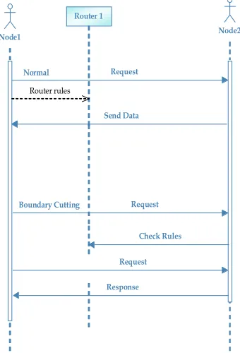
FIGURE 7: Class Diagram SEQUENCE DIAGRAM:
A sequence diagram in Unified Modeling Language (UML) is a kind of interaction diagram that shows how processes operate with one another and in what order. It is a construct of a Message Sequence Chart. Sequence diagrams are sometimes called event diagrams, event scenarios, and timing diagrams.
Node1 Node2
Router 1
Request Normal
Send Data
Request Boundary Cutting
Check Rules
Request
Response Router rules
ACTIVITY DIAGRAM:
Activity diagrams are graphical representations of workflows of stepwise activities and actions with support for choice, iteration and concurrency. In the Unified Modeling Language, activity diagrams can be used to describe the business and operational step-by-step workflows of components in a system. An activity diagram shows the overall flow of control.
FIGURE 9: Activity Diagram
INPUT DESIGN
The input design is the link between the information system and the user. It comprises the developing specification and procedures for data preparation and those steps are necessary to put transaction data in to a usable form for processing can be achieved by inspecting the computer to read data from a written or printed document or it can occur by having people keying the data directly into the system. The design of input focuses on controlling the amount of input required, controlling the errors, avoiding delay, avoiding extra steps and keeping the process simple. The input is designed in such a way so that it provides security and ease of use with retaining the privacy. Input Design considered the following things:
What data should be given as input?
How the data should be arranged or coded?
The dialog to guide the operating personnel in providing input.
Methods for preparing input validations and steps to follow when error occur.
OBJECTIVES
1.Input Design is the process of converting a user-oriented description of the input into a computer-based system. This design is important to avoid errors in the data input process and show the correct direction to the management for getting correct information from the computerized system.
2. It is achieved by creating user-friendly screens for the data entry to handle large volume of data. The goal of designing input is to make data entry easier and to be free from errors. The data entry screen is designed in such a way that all the data manipulates can be performed. It also provides record viewing facilities. 3. When the data is entered it will check for its validity. Data can be entered with the help of screens. Appropriate messages are provided as when needed so that the user will not be in maize of instant. Thus the objective of input design is to create an input layout that is easy to follow
OUTPUT DESIGN
A quality output is one, which meets the requirements of the end user and presents the information clearly. In any system results of processing are communicated to the users and to other system through outputs. In output design it is determined how the information is to be displaced for immediate need and also the hard copy output. It is the most important and direct source information to the user. Efficient and intelligent output design improves the system’s relationship to help user decision-making.
Conference Chair:Prof.Dr.G.ManojSomeswar, Director General, Global Research Academy, Hyderabad,
computer output, they should Identify the specific output that is needed to meet the requirements.
2. Select methods for presenting information.
3. Create document, report, or other formats that contain information produced by the system.
The output form of an information system should accomplish one or more of the following objectives.
Convey information about past activities, current status or projections of the
Future.
Signal important events, opportunities,
problems, or warnings. Trigger an action. Confirm an action.
SYSTEM ANALYSIS EXISTING SYSTEM:
Our study analyzed various decision-tree-based packet classification algorithms. If a decision tree is properly partitioned so that the internal tree nodes are stored in an on-chip memory and a large rule database is stored in an off-chip memory, the decision tree algorithm can provide very high-speed search performance. Moreover, decision tree algorithms naturally enable both the highest-priority match and the multimatch packet classification. Earlier decision tree algorithms such as HiCuts and HyperCuts select the field and number of cuts based on a locally optimized decision, which compromises the search speed and the memory requirement. This process requires a fair amount of preprocessing, which involves complicated heuristics related to each given rule set.
DISADVANTAGES OF EXISTING SYSTEM:
The computation required for the
pre-processing consumes much memory and construction time, making it difficult.
Algorithms to be extended to large rule sets because of memory problems in building the decision trees.
The cutting is based on a fixed interval, which does not consider the actual space that each rule covers; hence it is ineffective.
PROPOSED SYSTEM:
In this paper, we propose a new efficient packet classification algorithm based on boundary cutting. Cutting in the proposed algorithm is based on the disjoint space covered by each rule.
Hence, the packet classification table using the proposed algorithm is deterministically built and does not require the complicated heuristics used by earlier decision tree algorithms.
ADVANTAGES OF PROPOSED SYSTEM:
The boundary cutting of the proposed algorithm is more effective than that of earlier algorithms since it is based on rule boundaries rather than fixed intervals. Hence, the amount of required memory is significantly reduced.
Although BC loses the indexing ability at internal nodes, the binary search at internal nodes provides good search performance.
SYSTEM TESTING
TYPES OF TESTS Unit testing
Unit testing involves the design of test cases that validate that the internal program logic is functioning properly, and that program inputs produce valid outputs. All decision branches and internal code flow should be validated. It is the testing of individual software units of the application .it is done after the completion of an individual unit before integration. This is a structural testing, that relies on knowledge of its construction and is invasive. Unit tests perform basic tests at component level and test a specific business process, application, and/or system configuration. Unit tests ensure that each unique path of a business process performs accurately to the documented specifications and contains clearly defined inputs and expected results.
Integration testing
Integration tests are designed to test integrated software components to determine if they actually run as one program. Testing is event driven and is more concerned with the basic outcome of screens or fields. Integration tests demonstrate that although the components were individually satisfaction, as shown by successfully unit testing, the combination of components is correct and consistent. Integration testing is specifically aimed at exposing the problems that arise from the combination of components.
Functional test
Functional tests provide systematic demonstrations that functions tested are available as specified by the
business and technical requirements, system
documentation, and user manuals.
Functional testing is centered on the following items: Valid Input : identified classes of valid input must be accepted.
Invalid Input : identified classes of invalid input must be rejected.
Functions : identified functions must be exercised.
Output : identified classes of application outputs must be exercised.
Systems/Procedures: interfacing systems or procedures must be invoked.
Organization and preparation of functional tests is focused on requirements, key functions, or special test cases. In addition, systematic coverage pertaining to identify Business process flows; data fields, predefined processes, and successive processes must be considered for testing. Before functional testing is complete, additional tests are identified and the effective value of current tests is determined.
System Test
System testing ensures that the entire integrated software system meets requirements. It tests a configuration to ensure known and predictable results. An example of system testing is the configuration oriented system integration test. System testing is based on process descriptions and flows, emphasizing pre-driven process links and integration points.
White Box Testing
White Box Testing is a testing in which in which the software tester has knowledge of the inner workings, structure and language of the software, or at least its purpose. It is purpose. It is used to test areas that cannot be reached from a black box level.
Black Box Testing
Conference Chair:Prof.Dr.G.ManojSomeswar, Director General, Global Research Academy, Hyderabad,
Unit Testing:
Unit testing is usually conducted as part of a combined code and unit test phase of the software lifecycle, although it is not uncommon for coding and unit testing to be conducted as two distinct phases.
Test strategy and approach
Field testing will be performed manually and functional tests will be written in detail.
Test objectives
All field entries must work properly.
Pages must be activated from the identified link.
The entry screen, messages and responses must not be delayed.
Features to be tested
Verify that the entries are of the correct format
No duplicate entries should be allowed
All links should take the user to the correct page.
Integration Testing
Software integration testing is the incremental integration testing of two or more integrated software components on a single platform to produce failures caused by interface defects.
The task of the integration test is to check that components or software applications, e.g. components in a software system or – one step up – software applications at the company level – interact without error.
Test Results: All the test cases mentioned above
passed successfully. No defects encountered.
Acceptance Testing
User Acceptance Testing is a critical phase of any project and requires significant participation by the end user. It also ensures that the system meets the functional requirements.
Test Results: All the test cases mentioned above
passed successfully. No defects encountered.
IMPLEMENTATION MODULES:
Building a BC Decision Tree
Searching in the Boundary Cutting
Selective Boundary Cutting
Data Structure
MODULES DESCRIPTION: Building a BC Decision Tree
When the cutting of a prefix plane according to rule boundaries is performed, both the starting and the ending boundaries of each rule can be used for cutting, but cutting by either is sufficient since decision tree algorithms generally search for a subspace in which an input packet belongs and the headers of the given input are compared for entire fields to the rules belonging to the subspace (represented by a leaf node of the decision tree).
Searching in the Boundary Cutting
The cuts at each internal node of the BC decision tree do not have fixed intervals. Hence, at each internal node of the tree, a binary search is required to determine the proper edge to follow for a given input. During the binary search, the pointer to the child node is remembered when the input matches the entry value or when the input is larger than the entry value.
as that in the HiCuts or HyperCuts algorithm, is performed for rules stored in the leaf node.
Selective Boundary Cutting
In this module we propose a refined structure for the BC algorithm. The decision tree algorithms including the BC algorithm use binth to determine whether a subspace should become an internal node or a leaf node. In other words, if the number of rules included in a subspace is more than binth, the subspace becomes an internal node; otherwise, it becomes a leaf node. In the BC algorithm, if a subspace becomes an internal node, every starting boundary of the rules included in the subspace is used for cutting. We propose a refined structure using the binth to select or unselect the boundary of a rule at an internal node. In other words, the refined structure activates a rule boundary only when the number of rules included in a partition exceeds the binth.
Data Structure
There are two different ways of storing rules in decision tree algorithms. The first way separates a rule table from a decision tree. In this case, each rule is stored only once in the rule table, while each leaf node of a decision tree has pointers to the rule table for the rules included in the leaf. The number of rule pointers that each leaf must hold equals the binth. In searching for the best matching rule for a given packet or the list of all matching rules, after a leaf node in the decision tree is reached and the number of rules included in the leaf is identified, extra memory accesses are required to access the rule table. The other way involves storing rules within leaf nodes. In this case, search performance is better since extra access to the rule table is avoided, but extra memory overhead is caused due to rule replication. In our simulation in this paper, it is assumed that rules are stored in leaf nodes since the search performance is more important than the required memory.
RESULTS & CONCLUSION
In this research paper, decision tree algorithms have been studied, and a new decision tree algorithm is proposed. Throughout the extensive simulation using Classbench databases [38] for the previous decision tree algorithms, HiCuts and HyperCuts, we discovered that the performance of decision tree algorithms is highly dependent on the rule set characteristics, especially the number of rules with a wildcard or a short-length prefix. For example, the HiCuts algorithm can provide high-speed search performance, but the memory overhead for large sets or sets with many wildcard rules makes its use impractical. We also discovered that the HyperCuts algorithm either does not provide high-speed search performance or requires a huge amount of memory depending on how to implement the pushing upward optimization. While the cutting in the earlier decision tree algorithms is based on a regular interval, the cutting in the proposed algorithm is based on rule boundaries; hence, the cutting in our proposed algorithm is deterministic and very effective. Furthermore, to avoid rule replication caused by unnecessary cutting, a refined structure of the proposed algorithm has been proposed. The proposed algorithms consume a lot less memory space compared to the earlier decision tree algorithms, and it is up to several kilobytes per rule except for FW50K and FW100K. The proposed algorithms achieve a packet classification by 10–23 on-chip memory accesses and 1.0–4.0 off-chip memory accesses in average.
Conference Chair:Prof.Dr.G.ManojSomeswar, Director General, Global Research Academy, Hyderabad,
REFERENCES
[1] H. J. Chao, “Next generation routers,” Proc. IEEE, vol. 90, no. 9, pp.1518–1588, Sep. 2002.
[2] A. X. Liu, C.R.Meiners, andE.Torng, “TCAMrazor: A systematic approach towards minimizing packet classifiers in TCAMs,” IEEE/ACM Trans. Netw., vol. 18, no. 2, pp. 490–500, Apr. 2010.
[3] C. R. Meiners, A. X. Liu, and E. Torng, “Topological transformation approaches to TCAM-based packet classification,” IEEE/ACM Trans. Netw., vol. 19, no. 1, pp. 237–250, Feb. 2011.
[4] F. Yu and T. V. Lakshnam, “Efficient multimatch packet classification and lookup with TCAM,” IEEE Micro, vol. 25, no. 1, pp. 50–59, Jan. –Feb. 2005.
[5] F. Yu, T. V. Lakshman, M. A. Motoyama, and R. H. Katz, “Efficient multimatch packet classification for network security applications,” IEEE J. Sel. Areas Commun., vol. 24, no. 10, pp. 1805–1816, Oct. 2006.
[6] H. Yu and R. Mahapatra, “A memory-efficient hashing by multi-predicate bloom filters for packet classification,” in Proc. IEEE INFOCOM, 2008, pp. 2467–2475.
[7] H. Song and J. W. Lockwood, “Efficient packet classification for network intrusion detection using FPGA,” in Proc. ACM SIGDA FPGA, 2005, pp. 238– 245.
[8] P. Gupta and N. Mckeown, “Classification using hierarchical intelligent cuttings,” IEEE Micro, vol. 20, no. 1, pp. 34–41, Jan.–Feb. 2000.
[9] S. Singh, F. Baboescu, G. Varghese, and J. Wang, “Packet classification using multidimensional cutting,” in Proc. SIGCOMM, 2003, pp. 213–224.
[10] P. Gupta and N. Mckeown, “Algorithms for packet classification,” IEEE Netw., vol. 15, no. 2, pp. 24–32, Mar.–Apr. 2001.
[11] B. Vamanan, G. Voskuilen, and T. N. Vijaykumar, “EffiCuts: Optimizing packet classification for memory and throughput,” in Proc. ACM SIGCOMM, 2010, pp. 207–218.
[12] H. Song, M. Kodialam, F. Hao, and T. V. Lakshman, “Efficient trie braiding in scalable virtual routers,” IEEE/ACM Trans. Netw., vol. 20, no. 5, pp. 1489–1500, Oct. 2012.
[13] J. Treurniet, “A network activity classification schema and its application to scan detection,”
IEEE/ACM Trans. Netw., vol. 19, no. 5, pp. 1396–1404, Oct. 2011.
[14] L. Choi, H. Kim, S. Ki, and M. H. Kim, “Scalable packet classification through rulebase partitioning using
the maximum entropy hashing,” IEEE/ACM Trans.
Netw., vol. 17, no. 6, pp. 1926–1935, Dec. 2009.