Modified Interleaved Buck Converter with
Closed Loop Control for Higher Step Down
Conversion Ratio
Nirupama Bhaskaran1, Saritha K.S2
PG Student [PE], Dept. of EEE, Sree Narayana Gurukulam College of Engineering, Kadayiruppu, Kerala, India1
Associate Professor, Dept. of EEE, Sree Narayana Gurukulam College of Engineering, Kadayiruppu, Kerala, India2
ABSTRACT: This paper deals with Modified Interleaved Buck Converter with closed loop control for higher step down conversion ratio and lower ripple in the output current. With closed loop control it is possible to obtain a constant output for a range of input. This converter is suitable for applications requiring low output voltage. Three MOSFETs are connected in series with two coupling capacitors and closed loop control is provided with PI controller. The modes of operation, simulink model and corresponding simulation results are presented in this paper.
KEYWORDS: Modified interleaved buck converter (MIBC), Step down conversion ratio, Inductor current ripple
I.INTRODUCTION
Modified interleaved buck converter with closed loop control for higher step down conversion ratio is suitable for applications requiring high input voltage and low output voltage. MIBC (Modified Interleaved Buck Converter) is having lot of considerations due to its simple structure and reduced complexity in control. With closed loop control it is possible to obtain a constant output over a range. However in the earlier MIBC the output was not constant, it varies with input.
In this paper, it proposes MIBC with three active switches and two coupling capacitors. The converter acts in continuous conduction mode. If the converter operates in discontinuous conduction mode, all the elements suffer by current stress. Hence conduction loss and core loss of the converter will be increased. During steady state, the voltage stress across all active switches before turn on or after turn off is half of the input voltage. The conversion ratio, output current ripple, ripple in the inductor current are lower. By providing closed loop control the output is constant over a wide range hence it enhances the efficiency.
Modified interleaved buck converter consists of three buck converters connected in parallel. Interleaved stages are for reducing the ripple currents by operating two or more converter circuits (sub-circuits) in parallel and to operate the switches in respective sub-circuit with a phase shift with respect to each other. The phase difference between the operations of the two switches results in the ripple currents of one of the sub-circuits cancelling the ripple currents of the other. This reduces the ripple current in both the input and the output of the converter.
II.LITERATURE SURVEY
Changchien proposed interleaved four phase buck – based current source with isolated energy – recovery scheme for electrical discharge machine. (2009).In this paper it provides a major path for the inductor to release its stored energy. Hence it avoids high output voltage. Its limitation is that it has bulky volume. Peng Xu (2001) proposed a family of DC – DC converters which employs an innovative interleaving concept using series primary windings and interleaved parallel secondary sides. The advantages of this converter include reduced filter size, improved transient response and increased efficiency. Wu Chen Xinbo Ruan et al (2009) investigated the DC – DC conversion systems constructed from connecting multiple converter modules in series and parallel at both the input and output sides. They studied the control strategies aiming to achieve proper sharing of the voltage and current at the input and output sides. They also presented the relationship between sharing of input voltages or currents and output voltages or currents. In particular, the inherent stability of control operations applied at the input side and output side is analysed in their work.
III.CIRCUIT OPERATIONS
Fig 1:
Conventional Modified Interleaved Buck Converter [1]The fig above shows the Conventional Modified Interleaved Buck Converter. It has three active switches connected in series with two coupling capacitors in the power path. The switches S1, S2 and S3 are driven with phase shift angle of
1200. Each switching period is divided into three modes. The three inductors L1, L2 and L3 are having the same
inductance L. The coupling capacitors C1 and C2 are considered as the voltage source. All the power semiconducting
devices are ideal. Three buck converters connected in series. Here the switching pulses are provided to three switches at a phase delay of 33.330 .
Mode 1:
Mode 1 begins when S1 is turned ON. Then the current IL1 flows through S1, C1 and L1 and hence coupling
capacitor VC1 is charged. The current IL2 freewheels through D2 and current IL3 freewheels through D3. During this
mode voltage across L1 is the difference of the input voltage, voltage of the coupling capacitor VC1 and output voltage.
Hence IL1 increases linearly. IL2 and IL3 decreases linearly from the initial value.
Mode 2:
Mode 2 begins when S1 is turned OFF and S2 is turned ON. When S1 is turned OFF, currents IL1, IL2 and IL3
freewheels through D1, D2 and D3 respectively. The voltages become the negative output voltage and the current
capacitor VC2 is charged. Current Il2 flows through S2, C2 and L2. The current IL1 freewheels through D1 and IL3
freewheels through D3. In this mode voltage VL2 is the difference of coupling capacitor voltages and the output voltage.
Mode 3:
Mode 3 begins when S2 is turned OFF and S3 is turned ON. The energy stored in the coupling capacitor VC2 is
discharged. The current IL3 flows through C2, S3 and L3. The current Il1 freewheels through D1 and current IL2
freewheels through D2. During this mode the voltage VL3 is the difference between VC2 and V0. The voltage VL1 and
VL2 are the negative output voltages. Hence IL1 and IL3 decrease linearly from its initial values.
Fig 2 Output waveforms of MIBC [1]
IV. DESIGN EQUATIONS
Input Voltage = 25V Output Voltage =1.25V D = Vo/Vin
∆
i
L = Vo (1-D) Ts/L L= Vo(1-D) Ts/∆iLC = IoDTs /∆V
V.SIMULINK MODEL
For the MIBC with closed loop, the parameter specifications are as follows
1) Switching Frequency : Fs = 65KHz
2) Input Voltage : Vs = 25V
3) Output Voltage : Vo = 1.25V
4) Output Current : Io = 4A
5) Output ripple Voltage : Vo ripple = 0.125
6) Inductor ripple current : IL ripple = 0.8
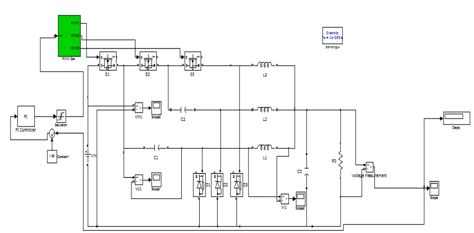
Fig 3 Simulink model of MIBC with closed loop control
VI.SIMULATION RESULT
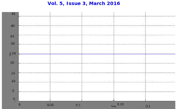
The simulation waveforms of input voltage and output voltage for the MIBC with closed loop control are shown in
Fig 4 Simulation waveform for input voltage of MIBC with closed loop control
Fig 5 Simulation waveform for output voltage of MIBC with closed loop control
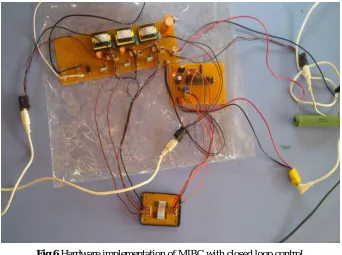
VII.HARDWARE IMPLEMENTATION
The experimental set up of the circuit is shown in the Fig 6. The converter circuit, control circuit and phase shift mask are shown.
Specifications:
Switching frequency = 65 kHz Input voltage = 25V
Output ripple Voltage = 0.125 Inductor ripple current = 0.8
Fig 6 Hardware implementation of MIBC with closed loop control
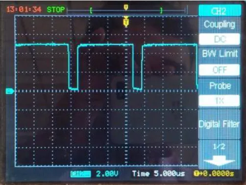
The waveforms of the output voltage and gate pulses to the switch S1 of hardware implementation is shown in the Fig 7
and Fig 8
Fig 8 Gate pulses to switch S1
VIII.CONCLUSION
Modified Interleaved Buck Converter with Closed Loop Control for higher step down conversion ratio is proposed in this paper. With closed loop control a constant output is obtained for a range of input and higher step down conversion ratio. The voltage stress across the switches is reduced considerably when the operating duty ratio is below 50%.The output ripple is also reduced with this interleaved buck converter.
REFERENCES
[1] Suja A, Sivakumar S, Ramkumar P.S “Modified interleaved Buck Converter Implementation for higher step down conversion ratio “ IEEE Conference on Innovations in Information Embedded and Communication Systems ICIECS’15
[2] P.l. Wong, P.Xu, B. Yang, and F.C.Lee, “Performance improvements of interleaving VRMs with coupling inductors” IEEE Trans. Power Electron, vol 168 no 4, pp. 499-507, jul.2001
[3] C Garcia, P Zumel, A.D. Castro and J.A. Cobos, “Automotive DC-DC bidirectional converter made with many interleaved buck stages,” IEEE Trans. Power Electron, vol.21, no.21, pp.578-586, May 2006
[4] Y.C Chuang “High Efficiency ZCS buck converter for rechargeable batteries,” IEEE Trans. Ind.Electron, vol 57,no 7,pp.2463-2472, Jul 2010 [5] K. Yao, M Ye, M.Xu, and F.C. Lee, “Tapped inductor buck converter for high step down DC-DC conversion,” IEEE Trans. Power Electron,
vol 20, no 4, pp.775-780, Jul.2005
![Fig 1: Conventional Modified Interleaved Buck Converter [1]](https://thumb-us.123doks.com/thumbv2/123dok_us/7779989.1284614/2.595.72.521.314.539/fig-conventional-modified-interleaved-buck-converter.webp)
![Fig 2 Output waveforms of MIBC [1]](https://thumb-us.123doks.com/thumbv2/123dok_us/7779989.1284614/3.595.142.457.288.574/fig-output-waveforms-of-mibc.webp)