Design and Implementation of Multilevel
Inverter with Battery Harmonizing
Pratima S Uplaonkar
1, Mina Vagha
2Assistant Professor, Dept. of Basic Engineering, Indira College Engineering & Management, Pune, Maharashtra, India1 Assistant Professor, Dept. of Electrical Engineering, AISSMS College of Engineering, Pune, Maharashtra, India2
ABSTRACT: The structure of the multilevel inverter using cascaded-inverters with battery balancing is proposed. The input of each individual inverter is directly connected to a battery. In this paper, the general structure of multi-level converter with battery balancing is to synthesize a near sinusoidal voltage from several levels of dc voltages stored in battery bank, typically from capacitor voltage sources. As the number of levels increases, the synthesized output waveform has more steps, which provides a staircase wave that approaches a desired waveform. Also, as steps are added to waveform, the harmonic distortion of the output wave decreases, approaching zero as the number of voltage levels increases.
A difference in cell voltages is a most typical manifestation of unbalance, which is attempted to be corrected either instantaneously or gradually through by-passing cells with higher voltage. This presentation explains existing underlying causes of voltage unbalance, discusses trade-offs that are needed in designing balancing algorithms and which is given as input to the multilevel inverter.
KEYWORDS:Multilevel inverter, Battery balancing.
I.INTRODUCTION
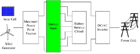
With the increasing ultimatum and continuous diminution of fossil fuel reserves, renewable energy sources have gained significant importance in generation of electricity. Assimilating the renewable energy sources with power grid affects the voltage/frequency leading to serious power quality issues as renewable energy sources are intermittent in nature and produce unstable active power[1]-[6]. In order to overcome the concerns the power generated can be stored in the battery. To increase the capacity of storage and reduce the transmission losses, the batteries can be connected in successions.[1], [2], [7], [8]-[11].
Many battery balancing techniques have been proposed which can be classified as i) dissipative battery balancing [12], [13] and ii) Non dissipative battery balancing.[14]- ]-[20].
Fig. 1: Renewable energy systems
Due to battery balancing circuit the complexity and the cost of the circuit and also the efficiency is reduced. To overcome this single phase multilevel inverter with battery harmonizing is proposed, which can be controlled such that the battery is balanced and the harmonics are reduced.
II.SYSTEM DESCRIPTION
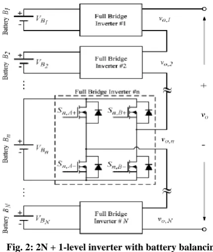
Among all the topologies for multilevel inverter, cascaded multilevel inverter is the superior to all other topologies. Input to each bridge is given by separate voltage source in the form of a battery which consists of the stored energy, produced by the renewable energy sources and is cascaded with other sources via a special H-bridge circuit associated with it. Each of the circuit consists of four switching elements which can produce the corresponding output voltage source in positive or negative polarity and zero volts, depending on the switching condition of the switches in the inverter circuit. The output is 2N+1 level; where N is the number of full bridge inverter or the number of batteries is as shown below.[23]
Fig. 2: 2N + 1-level inverter with battery balancing
The output of the cascaded multilevel inverter is the sum of output produced by the individual full bridge inverter.
III.BATTERY HARMONIZING
The N batteries are carefully chosen for N levels of inverter and the set of batteries can be defined as
B={B1,B2,……..Bn,…..BN} (1)
If the characteristics of all the batteries are equal, switching pattern swapping scheme can be adopted to achieve battery balancing. Suppose the characteristics of any two batteries are different, the battery set B is sorted, and the sorted battery set Bsort is attained.
B sort={B*1, B*2, B*3…… B*n………… B*N} (2)
in which VBn *
< VBn-1
*, n=1,2,……N. The battery with highest voltage is denoted by B*
1.and battery with second
highest voltage as B*2 and so on. Using Fourier series the RMS voltage and hthharmonic the output wave can be
expressed as
the switching angles α1, α2, . . . , αNcan be found such that the THD is underestimated and the rms of the fundamental
frequency is close to the reference voltage v1,rms_ref . After that, M batteries for output voltage are categorized according
to the switching angles α1, α2, . . . , αN.
Finally,theseM batteries with higher voltage are preferred and shown as
BM=={B*1, B*2, B*3………B*M} (4)
The output voltage of the multilevel inverter can be expressed as
V0=VB1* + VB2* + ………VBM* (5)
The battery voltages VB1, VB2 andVB3 are measured at ωt=0 and ωt=π and then batteries are sorted.
Bsort = {B*1, B*2, B*3} (6)
The RMS voltage of fundamental frequency, third and fifth order harmonic equations can be expressed as the following according to (3):
v1,rms(α1, α2, α3) = 4/√2π [VB∗1cos(α1) + VB∗2cos(α2)+VB∗3cos(α3)] (7)
v3,rms(α1, α2, α3) =4/3√2π [VB∗1cos(3α1) + VB∗2cos(3α2)+VB∗2cos(3α3)] (8)
v5,rms(α1, α2, α3) =4/5√2π [VB∗1cos(5α1) + VB∗2cos(5α2)+VB∗3cos(5α3)]. (9)
By using Newton Raphson method we can find angles α1,α2and α3 to meet 9). If the switching angles cannot meet
(7-9) then (7) will be priority.
All switch states are obtained according to α1,α2and α3. Finally, function of battery balancing and the harmonic
reduction in the seven level inverter can be achieved.
The discharging capacity of a battery with higher voltage is greater than that of the battery with lower voltage. Thus battery balancing is realized.
IV.NEWTON-RAPHSON METHOD FOR CALCULATING SWITCHING ANGLE
The Fourier series expansion of output voltage waveform using fundamental frequency switching scheme can be expressed as
Vo(ωt)=4vdc/nπ[cosɵ1+cos ɵ2+cos ɵ3] (10)
The switching angles can be found by solving
cosɵ1+cos ɵ2+cos ɵ3= m (11)
cos3ɵ1+cos3ɵ2+cos3ɵ3=0 (12)
cos5ɵ1+cos5ɵ2+cos5ɵ3=0 (13)
where m is modulation index m=V1π/4Vdc.
X1= cosɵ 1, X2= cosɵ 2, X3= cosɵ 3, X4= cosɵ 4X5= cosɵ 5, X6= cosɵ 6, X7= cosɵ 7 (14)
Cos3ɵ = 4cos3ɵ -3cosɵ (15)
Cos5ɵ = 5cosɵ -20cos3ɵ +16cos5ɵ (16)
Above set of non- linear equation can be solved by using Newton-Raphson method and switching angles can be optimized to achieve battery balancing and minimizing the harmonics.
V. SIMULATION AND RESULTS
The performance of the multilevel inverter with battery balancing is verified through the simulation results.
Solar model was simulated and the circuit for the same is as shown below, the output of which is stored in battery and this is given as input to the individual full bridge inverter.
Fig.3: Simulation of solar cell.
For battery balancing we have used here three battries.B1=44V,B2=48V,B3=52V, we have taken switch condition to the
battery.The Switch block passes through the first input or the third input based on the value of the second input. The first and third inputs are called data inputs. The second input is called the control input. Here I have taken control input as 48 v .1st data input 44v and third 54v. If control input is greater than
48, it will shift towards third
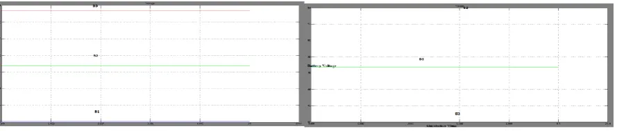
input. if control input is less than 48 then it will shift toward first input, then if one of battery is default .then we are just transferring first battery to the third and third to first.Fig. 4: Battery Voltages a)beforebattery balancing b)after battery balancing
It can be seen that before battery balancing B1 = 40V; B2 = 47V and B3 =53V; afterbatterybalancingisachievedB3 = 40V;B1 = 47V andB2 = 53V; accordingtotheconditionVB2<VB1< VB3,i.e; battery with higher voltage discharges upto a
threshold valueand thus battery balancing is achieved
.
Fig. 5: Overall Simulation of the System
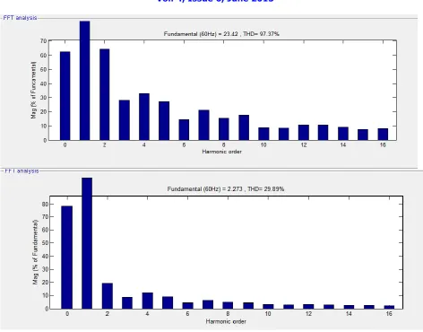
Fig. 7: FFT Analysis a)without filter b)with filter
From the FFT analysis we can see that the THD without filter is 97.37% and with filter the THD is 29.89%.
VI.CONCLUSION
In this paper,a multilevel inverter with battery balancing is simulated successfully. The input to the individual full bridge inverter was given through a battery which was stored by the energy generated by the solar cell. Depending on the battery’s voltage battery balancing function was implemented and corresponding switching pulses were also generated, thus battery balancing is achieved.
VII.ACKNOWLEDGEMENT
I acknowledge Indira College of Engineering & Management for sponsoring me and promoting me for higher studies and research. I also acknowledge my guide Prof. M A Vagha for her valuable guidance and AISSMS COE for providing the infrastructure.
REFERENCES
[1] Hirose, T. and Matsuo, H. “Standalone hybrid wind–solar power generation system applying dump power control without dump load,”
IEEETrans. Ind. Electron., vol. 59, no. 2, pp. 988–997, 2012.
[2] Kanchev, H., Lu, D., Colas, F., Lazarov, V. and Francois, B. “Energy management and operational planning of a microgrid with a PV-based active generator for smart grid applications,” IEEE Trans. Ind. Electron., vol. 58,no. 10, pp. 4583–4592, 2012.
[3] Haihua, Z., Bhattacharya, T., Duong, T.,Siew, T. S. T. and Khambadkone, A. M. “Composite energy storage system involving battery and ultracapacitor with dynamic energy management in microgrid applications,” IEEE Trans. Power Electron., vol. 26, no. 3, pp. 923–930, 2011. [4] Qian, H., Zhang, J., Lai, J. S. andYu, W. “A high-efficiency grid-tie battery energy storage system,” IEEE Trans. Power Electron., vol. 26, no.
[5] Kouro, S., Malinowski, M., Gopakumar, K., Pou, J., Franquelo, L. G., Wu B., Rodriguez, J., Pérez, M. A. and Leon, J. L. “Recent advances and industrial applications of multilevel converters,” IEEE Trans. Ind. Electron., vol. 57, no. 8, pp. 2553–2580, 2010.
[6] Abbey, C and Joos, G “Supercapacitor energy storage for wind energy applications,” IEEE Trans. Ind. Appl., vol. 43, no. 3, pp. 769–776, 2007. [7] Chen, B. Y and Lai, Y. S “New digital-controlled technique for battery charger with constant current and voltage control without current
feedback,” IEEE Trans. Ind. Electron., vol. 59, no. 3, pp. 1545–1553, 2012.
[8] Chen, L. R., Young, C. M., Chu, N. Y. and Liu, C. S.“Phase-locked bidirectional converter with pulse charge function for 42-V/14-V dualvoltagePowerNet,” IEEE Trans. Ind. Electron., vol. 58, no. 5, pp. 2045– 2048, 2011.
[9] Liu Y. H and Luo, Y. F. “Search for an optimal rapid-charging pattern for Li-ion batteries using the Taguchi approach,” IEEE Trans. Ind. Electron., vol. 57, no. 12, pp. 3963–3971, 2010.
[10] Chen, L.“Design of duty-varied voltage pulse charger for improving Li-ion battery-charging response,” IEEE Trans. Ind. Electron., vol. 56, no. 2, pp. 480–487, 2009.
[11] Chen, J. J., Yang, F. C., Lai, C. C., Hwang, Y. S. and Lee, R. G. “A high-efficiency multimode Li-ion battery charger with variable current source and controlling previous-stage supply voltage,” IEEE Trans. Ind.Electron., vol. 56, no. 7, pp. 2469–2478, 2009.
[12] Chen, L. R., Liu, C. S. and Chen, J. J. “Improving phase-locked battery charger speed by using resistance-compensated technique,” IEEE Trans.Ind. Electron., vol. 56, no. 4, pp. 1205–1211, 2009.
[13] Chen, L.R., Hsu, R. C. and Liu, C. S. “A design of a grey-predicted Li-ion battery charge system,” IEEE Trans. Ind. Electron., vol. 55, no. 10, pp. 3692–3701, 2008.
[14] Chen, L. R., Chen, J. J., Chu, N. Y and Han, G.Y. “Current-pumped battery charger,” IEEE Trans. Ind. Electron., vol. 55, no. 6, pp. 2482– 2488, 2008.
[15] Pahlevaninezhad, M., Drobnik, J., Jain, P. K. and Bakhshai, A. “A load adaptive control approach for a zero-voltage-switching dc/dc converter used for electric vehicles,” IEEE Trans. Ind. Electron., vol. 59, no. 2, pp. 920–933, 2012.
[16] Fakham, H., Lu, D and Francois, B. “Power control design of a battery charger in a hybrid active PV generator for load-following applications,”
IEEE Trans. Ind. Electron., vol. 58, no. 1, pp. 85–94, 2011.
[17] Vazquez, S., Lukic, S. M., Galvan, E., Franquelo, G. L. and Carrasco, J. M. “Energy storage systems for transport and grid applications,” IEEE Trans.Ind. Electron., vol. 57, no. 12, pp. 3881–3895, 2010.
[18] Jin, K., Yang, M., Ruan, X. and Xu, M. “Three-level bidirectional converter for fuel-cell/battery hybrid power system,” IEEE Trans. Ind. Electron., vol. 57, no. 6, pp. 1976–1986, 2010.
[19] Xu, A., Xie, S. and Liu, X. “Dynamic voltage equalization for seriesconnectedultracapacitors in EV/HEV applications,” IEEE Trans. Veh.Technol., vol. 58, no. 8, pp. 3981–3987, 2009.
[20] Yuanmao, Y., Cheng, K. W. E. and Yeung, Y. P. B. “Zero-current switching switched-capacitor zero-voltage-gap automatic equalization system for series battery string,” IEEE Trans. Power Electron., vol. 27, no. 7, pp. 3234–3242, 2012.
[21] Park, S. H., Park, K. B., Kim, H. S., Moon, G. W. and Youn, M. J. “Singlemagnetic cell-to-cell charge equalization converter with reduced number of transformer windings,” IEEE Trans. Power Electron., vol. 27, no. 6, pp. 2900–2911, 2012.
[22] Park, S. H., Kim, C. E., Kim, C. H.,G. Moon, G. W. and Lee, J. H. “A modularized charge equalizer for an HEV lithium-ion battery string,”
IEEE Trans. Ind. Electron., vol. 56, no. 5, pp. 1464–1476, 2009.
[23] Chiasson, J. N., Tolbert, L. M., McKenzie, K. J. and Du, Z. “Elimination of Harmonics in a Multilevel Converter Using the Theory of Symmetric Polynomials and Resultants,” IEEE Transactions on Control Systems Technology, Vol. 13, No. 2, pp. 216- 223. 2005.
[24] Lai, J. S. and Peng, F., “Multilevel converters–A new breed of power converters”, IEEE Trans. Ind. Appl., Vol. 32, pp. 509–517, 1996.
BIOGRAPHY