Simulation of Real and Reactive Power
Coordination Using CSC Based IPFC for
Power Quality Issues
S.Devi1, V.Suvitha2, E.Mageswari3, M.Yuvaleela4
Assistant Professor, Dept. of EEE, Prathyusha Institute of Technology and Management, Tamilnadu, India 1
Assistant Professor-I, Dept. of EEE, Prathyusha Institute of Technology and Management, Tamilnadu, India 2
Assistant Professor-I, Dept. of EEE, Prathyusha Institute of Technology and Management, Tamilnadu, India 3
Assistant Professor, Dept. of EEE, Prathyusha Institute of Technology and Management, Tamilnadu, India 4
ABSTRACT: FACTS technologies allow for improved transmission system operation with minimal infrastructure investment, environmental impact and implementation time compared to the construction of new transmission lines. FACTS provide the needed corrections of transmission functions in order to efficiently utilize existing transmission systems and therefore minimize the gap between the stability and the thermal level. Interline Power Flow Controller(IPFC) is a Voltage Source Converter(VSC) based FACTS controller for controlling power in multi-line system located at a substation. The main aim of the IPFC is to verify the power transfer capability between two or more lines and to establish the proposed voltage regulation function. In this paper, a current source converter topology based IPFC is proposed. In this structure, the dc-side current is regulated to a value larger than the peak value of the maximum line current. The injected voltage is controlled according to the desired reactive power compensation and management active power flow for master line. The decoupled state feedback control for the injected voltage with a separated dc current control is applied to the proposed system. The proposed IPFC has been simulated using the Matlab program.
KEYWORDS: IPFC, CSC, Linear model, non linear model
I. INTRODUCTION
Three main variables that can be directly controlled to impact its performance are voltage, angle and impedence. The power quality can be mainly affected by voltage sags, harmonics, voltage fluctuations and flicker and transients. The family of compensators and power flow controllers based on VSC are the Static Synchronous Series Compensator(STATCOM), the Static Synchronous Series Compensator(SSSC), the Unified Power Flow Controller(UPFC) and the Interline Power Flow Controller (IPFC). The FACTS controllers can be realized by either a voltage-source converter (VSC) or a Current Source Converter (CSC). But, in this paper, the choice of CSC over VSC because of the advantages such as since input current is maintained constant, the misfiring of switching devices or short circuit across source would not be a serious problem, the peak current of power devices is limited, large dc link filter acts as a current limiter making it easier to apply protective fuses.The IPFC has the capability to transfer real power between the compensated lines in addition to executing the independent and controllable reactive power compensation of each line. This capability makes it possible to equalize both real and reactive power flow between the lines to transfer power demand from overloaded to underloaded lines to compensate against resistive line voltage drops and the corresponding reactive line power and to increase the effectiveness of the compensating system for dynamic disturbance like transient stability, harmonics and power oscillations.In this paper, IPFC based on the current source converter topology is proposed. For simplicity, we analyse the IPFC with only two CSC, in which one CSC is called Master CSC, while the other CSC is called Slave CSC, which provides appropriate power to the Master CSC so that it can only regulate one variable.
LITERATURE SURVEY
[2]I.yugyi, “Dynamic Compensation of AC Transmission Lines by Solid-state Synchronous Voltage Sources”, IEEE Transactions on Power Delivery, vol. 9, no.2, April 1994,p.904-911.
[3] Hingorani.N.G, Gyugyi.L, Understanding FACTS Devices, IEEE Press 2000.
[4] Laszlo Gyugyi, Kalyan K.Sen, Colin D. Schauder, “The Interline Power Flow Controller Concept: A new Approach to Power Flow Management in Transmission System,” IEEE Trans. Power Delivery,vol.14,no.3,pp.1115-1123,1999.
II.SIMULATION OF REAL AND REACTIVE POWER COORDINATION OF CSC BASED IPFC
The simulation circuit diagram of a CSC based IPFC is shown in fig1. It is connected in series with the transmission lines through three single transformers. The primary side of each transformer is connected in series with the transmission line. The secondary sides of transformers are connected in Y form. The main functions of IPFC control system are dc-side current regulating and introduce proper control signals in order to exchange the required active and reactive power with AC power system.In Fig.1, transformers are modeled as a combination of an ideal transformer and R-L impedence. The series CSC injects its output voltage in the transmission line via a series coupling transformer. In this paper, we use injected voltage source model of IPFC for fundamental frequency studies in which by regulating the amplitude and angle of its output voltage it can change both the active and reactive power in the line.
The CSC can be controlled by the tri-level SPWM technique [7] in which case it behaves as a 3-phase linear power amplifier. The CSC under tri-level SPWM control can be modeled as:
iia1 = ma1Idc1 (1)
iib1 = mb1Idc1 (2)
iic1 = mc1Idc1 (3)
iia2 = ma2Idc2 (4)
iib2 = mb2Idc2 (5)
iic2 = mc2Idc2 (6)
The power balance equation for the IPFC considered is: Pse1 + Pse2 = PRloss + Pdc (7)
Where Pse1 and Pse2 are three phase instantaneous AC power going into series converter 1 (Master line) and series converter 2(slave line) respectively, while PRloss represents losses in converter circuits and Pdc is the DC power at DC inductor. By neglecting transformer losses and assuming fundamental frequency balanced conditions, three phase instantaneous powers, for the series converter 1 and 2, respectively, are given as: Pse1 = 3Iaca1Vinj1cos(δ1) (8)
Pse2 = 3Iaca2Vinj2cos(δ2) (9)
In equations (8),(9), Iaca1, Iaca2 are RMS values of transmission line currents; Vinj1 Vinj2 are RMS values of voltages across the primary side of series transformers; while angles δ1 and δ2 represent phase shift between line currents and series inserted voltages. The DC current equation can be obtained by substituting Pse1 and Pse2 by equation (7), (8) and (9): IdcLdcd/dtIdc +RdcIdc2 = 3Iac1Vinj1cos(δ1)+3Iac2Vinj2cos(δ2) (10) Where mal,, mbl, mcl and ma2 ,mb2, mc2 are the modulation indexes of the 3 phases, normalized to the peak of the triangular carrier signal. The modulation signals can also be transformed into d-q frame. Thus, (1) to (6) can be re-written as: Iid1 = Md1Idc1 (11)
Iiq1 = Mq1Idc1 (12)
Iid2 = Md2Idc2 (13)
Iiq2 = Mq2Idc2 (14)
Consider the line current of phase- a in Master line as the reference phasor for the d-q transformation for variable of the reference phasor for the d-q trnaformation for variables os Slave line, the dynamitic equations from the converter to the secondary side of the transformer are: d/dt(Vd1 ) =1/c1(Id1) +ωVq1-1/c1(Md1Idc1) (15)
d/dt(Vq1)) =-ωVd1-1/c1Mq1Idc1 (16)
d/dt(Vd2) = 1/c2(Id2)+ωVq2 -1/c2(Md2Idc2) (17)
d/dt(Vq2) = -ωVd2-1/c2(Mq2Idc2) (18)
The input variable, are Md1, Mq1 , Md2 and MQ2 and the output variable are IDc and Vd1, Vq1 and Vd2, Vq2 that givn by equation (10), (1) to (18) which are chosen based on the control objectives of the IPFC. The above system is nonlinear. A common method to deal with the nonlinearity is to linearization the equations around an operating point. But, in this particular case, since the nonlinearity is caused by Id.and the dynamics of Id, is slower than those of Vd and Vq, it is possible to divide the system into an inner control loop and an outer control loop, where the two loops can be deal with separately. The inner loop is the linear part of the system. The model is: d/dt(Vd1 ) =1/c1(Id1) +ωVq1-1/c1(Iid1) (19)
d/dt(Vq1)) =-ωVd1-1/c1Iiq1 (20)
d/dt(Vd2) = 1/c2(Id2)+ωVq2 -1/c2(Iid2) (21)
d/dt(Vq2) = -ωVd2-1/c2(Iiq2) (22)
In this system, Iid1, Iiq1, Iid2 and Iiq2 are the inpts, Vd1, Vq1, Vd2 and Vq2 are the state variables, as well as the outputs, (w, C1 and C2 are constant values, and Id1,Id2 is the line current). From the control view, Id1, Id2 can be considered as a ‘measurable disturbance input’, since it is neither a state variable, nor an input or output. The dynamic model in the matrix form is: Ẋ = AX + BU + Fe (23)
Y = CX (24) Where,
U = [Iid1 Iiq1 Iid2 Iiq2]T; e = [Id1 Iq1]T; Y = [Vd1 Vq1 Vd2 Vq2]T;
For a linear system represented by (23) and (24), it is easy to design a stable feedback controller so that the output variables follow the reference input variables and are not influenced by the disturbance input. The controller can be in the form of
U = -KX + TYref +Me (25) Where
Yref = Vd1ref Vq1ref Vd2ref Vq2ref ]T is the reference input.
K is a 2X2 constant state feedback matrix; T is a 2X2 constant diagonal gain matrix; and M is a 2X1 constant vector.
III. TEST SYSTEM AND RESULTS
The test power system (Fig.1) which has been modeled with Matlab is consist of two identical transmission systems. The simulated power system is composed of two voltage sources at the sending and receiving ends of a transmission lines. The test system parameters are given in the Appendix.
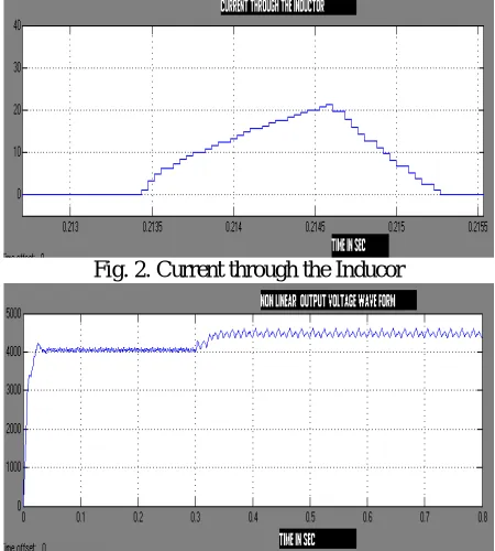
Figure 2-10 show how the system responses for Linear and non-linear loads in Master line and Slave line.
Fig. 2. Current through the Inducor
Fig.3. Non linear output voltage in Master line
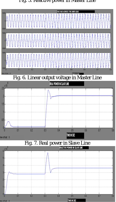
Fig. 5. Reactive power in Master Line
Fig. 6. Linear output voltage in Master Line
Fig. 7. Real power in Slave Line
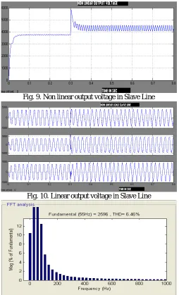
Fig. 9. Non linear output voltage in Slave Line
Fig. 10. Linear output voltage in Slave Line
Fig. 11. Total Harmonic Distortion (THD) waveform for with IPFC
IV. CONCLUSION
In this paper, the IPFC based on the current source converter (CSC) topology is proposed. The dynamic model of the system is derived and divided into a linear part and a nonlinear part. The linear part is controlled in an inner loop by a decoupled state feedback controller. The nonlinear part is controlled in an outer loop by a PI controller which regulates the dc side current. The steady state performance of the IPFC are evaluated using the simulation results from Matlab program.
I. APPENDIX
System data is referred with Pbase=25MVA, Vbase=3.3KV. The value of Ldc-30mh, f=50Hz, RL1=RL2=RL3=10Ω,
REFERENCES
[1]Pranesh Rao, M.L. Crow and Zhiping yang, “STATCOM Control for Power system Voltage Control Applications,” IEEE Transactions on Power Delivery, vol. 15, No. 4, October 2000, pp.1311-1317.
[2]I.yugyi, “Dynamic Compensation of AC Transmission Lines by Solid-state Synchronous Voltage Sources”, IEEE Transactions on Power Delivery, vol. 9, no.2, April 1994,p.904-911.
[3] Hingorani.N.G, Gyugyi.L, Understanding FACTS Devices, IEEE Press 2000.
[4] Laszlo Gyugyi, Kalyan K.Sen, Colin D. Schauder, “The Interline Power Flow Controller Concept: A new Approach to Power Flow Management in Transmission System,” IEEE Trans. Power Delivery,vol.14,no.3,pp.1115-1123,1999.
[5] L.Gyugyi, k.k.sen, C.D.Schauder, “The Interline Power flow controller Concept: A new Approach to Power Flow Management in Transmission Systems”, IEEE/PES Summer Meeting, Paper No. PE316-PWRD-0-07-1998, San Diego,July 1998.
[6] Jianhong Chen, Tijing T.Lie, D.M.Vilathgamuwa, “Design of an Interline Power Flow Controller”, 14th PSCC, Sevilla, Spain, June 24-28, 2002.