Back EMF Difference based Sensorless Speed
Control of B-4 Inverter Fed three phase
BLDC
Motor Using Fuzzy Logic Controller
Celus Sheena Francis 1, Caroline Ann Sam 2 , Jayasri.R.Nair 3
P.G. Student, Department of EEE, Rajagiri School of Engineering and Technology, Kakkanad, Kerala, India1
Assistant Professor, Department of EEE, Rajagiri School of Engineering and Technology, Kakkanad, Kerala, India2
Assistant Professor, Department of EEE, Rajagiri School of Engineering and Technology, Kakkanad, Kerala, India3
ABSTRACT: Brushless DC motors have gained popularity in electric drives applications such as industrial automotive equipments, instrumentations, aerospace etc due to its higher effciency, greater reliability, good dynamic response and very low maintenance. This paper presents speed control of four swich three phase inverter fed BLDC with fuzzy logic implementation.Cost saving is achieved by reducing the number of components in the inverter circuit by implementing four switch topology.The sensorless techniques based on the back EMF difference estimation method is suggested.The design analysis and simulation of the proposed system is done using MATLAB/SIMULINK software.Also, simulation results of sensored drive using PI controller and sensorless drive using fuzzy logic controller are analyzed.
KEYWORDS: Brushless dc motor, Hall sensored drive , PI controller, Back EMF sensorless drive, Fuzzy logic controller
I.INTRODUCTION
Brushless dc (BLDC) motors have been used for small horsepower control motors due to their high effciency, silent operation, compact form, reliability, and low maintenance. However, the control complexity for variable speed control and the high cost of the electric drive are the limitations for the widespread use of brushless dc motor in industries. Over the last decade, microprocessors/logic ICs, adjustable speed drivers (ASDs) control schemes and permanent magnet brushless electric motor production have combined to enable reliable, cost-effective solution for a broad range of adjustable speed applications. Household appliances are expected to be one of fastest-growing end-product market for electronic motor drivers (EMDs) over the next five years .
A standard three phase voltage source inverter consists of six switches for three legs called Six Switch Three Phase Inverter (SSTPI). A reduced switch count is designed for voltage source inverter consists of four switches i.e. Four Switch Three Phase Inverter (FSTPI) uses only three legs, with four switches and two capacitors is employed .
ISSN (Print) : 2320 – 3765 ISSN (Online): 2278 – 8875
I
nternational
J
ournal of
A
dvanced
R
esearch in
E
lectrical,
E
lectronics and
I
nstrumentation
E
ngineering
(An ISO 3297: 2007 Certified Organization)
Website: www.ijareeie.com
Vol. 6, Issue 2, February 2017
mechanical position sensor . The back EMF signal is directly related to the speed of the motor. Some of the advantages obtained by avoiding this mechanical sensor in control system of BLDC motor are: Lighter in weight, Compactness in size, Reduction in overall cost, Reliable during operating condition.
This paper develops to remove the drawbacks associated with sensored control ,reduced number of switches and use of traditional controllers by using zero crossing point (ZCP) of Back electromotive force (Back-EMF).Also, sensorless control is implemented with fuzzy logic controller. The sensorless control requires good reliability and various speed ranges with the high starting torque for BLDC motor drive system. To satisfy these requirements, this paper proposes an efficient sensorless speed control to avoid high energy prices.
II.FOUR SWITCH INVERTER FED THREE PHASE BLDC MOTOR
A BLDC motor needs quasi-square current waveforms, which are synchronized with the back EMFs to generate constant output torque and have 120 degree conduction and 60 degree non-conducting regions. Also, at every instant only two phases are conducting and the other phase remains inactive. Compared with the conventional six-switch three-phase inverter for the BLDC motor, the whole working process of the four switch inverter fed three phase BLDC motor is divided into six modes. Phase c involves four modes, including modes 2, 3, 5, and 6. Only one switch should work in the four modes. These modes are divided into two sub operating modes. In modes 1 and 4, phases a and b have current owing through them, and Ic should be zero. Figure 1 shows four switch three phase inverter fed BLDC motor.
Fig.1:Four switch inverter fed three phase BLDC motor
III.SENSORLESS CONTROL OF BLDC MOTOR
A. CONVENTIONAL BACK EMF DETECTION METHOD
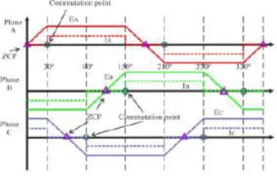
Fig 2: Zero crossing points of the back-emf and phase current commutation points
This technique of delaying 30 (electrical degrees) from zero crossing instant of the back-EMF is not affected much by speed changes. To detect the ZCPs, the phase back-EMF should be monitored during the silent phase.
B.PROPOSED BACK EMF DIFFERENCE ESTIMATION METHOD
Instead of using phase BEMF, the proposed method utilizes difference in BEMF of two phases. In the proposed method the commutation can be done at the ZCP itself which is depicted in figure 3. Thus the optimal performance is guaranteed
Fig 3: Zero crossing points of the back-emf difference and phase current commutation points without any phase shift
ISSN (Print) : 2320 – 3765 ISSN (Online): 2278 – 8875
I
nternational
J
ournal of
A
dvanced
R
esearch in
E
lectrical,
E
lectronics and
I
nstrumentation
E
ngineering
(An ISO 3297: 2007 Certified Organization)
Website: www.ijareeie.com
Vol. 6, Issue 2, February 2017
Table 1:Commutation sequence in back emf difference estimation method
IV. DESIGN OF FUZZY CONTROLLER
The generated signals are employed in fuzzy controller and PWM signals which in gate driver circuit is produced for control system. The fuzzy controller is composed of the following four elements fuzzification, fuzzy rule-base, fuzzy inference engine and defuzzification. Figure 4 shows the basic structure of a fuzzy logic controller.
Fig.4:Basic structure of a fuzzy logic controller
Error (e) and change in error (ce) are the inputs for the fuzzy controller whereas the output of the controller is change in
duty cycle (Δdc). The error is defined as the difference between the ref speed and actual speed, the change in error is
defined as the difference between the present error and previous error and the output, the Change in duty cycle which
could be either positive or negative and added with the existing duty-cycle to determine the new duty-cycle. Fuzzy logic uses linguistic variables instead of numerical variables. The process of converting a numerical variable in to a linguistic variable is called fuzzification. Fuzzy logic linguistic terms are most often expressed in the form of logical implications, such as If-Then rules. These rules define a range of values known as fuzzy membership functions. Fuzzy membership functions may be in the form of a triangle, a trapezoid or a bell.
Table 2:Membership function
V.SIMULATIONCIRCUITANDITSRESULTS
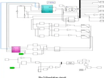
Fig. 5 shows the MATLAB simulation diagram of speed control of Four switch three phase inverter fed BLDC motor using fuzzy logic controller.
Fig 5:Simulation circuit
ISSN (Print) : 2320 – 3765 ISSN (Online): 2278 – 8875
I
nternational
J
ournal of
A
dvanced
R
esearch in
E
lectrical,
E
lectronics and
I
nstrumentation
E
ngineering
(An ISO 3297: 2007 Certified Organization)
Website: www.ijareeie.com
Vol. 6, Issue 2, February 2017
Fig 6:Variation of Back EMF signal with reference set at 1500rpm with PI controller
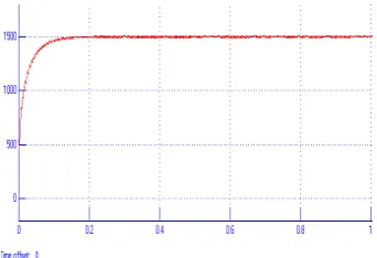
Fig 7:Variation of speed signal with reference set at 1500rpm with PI controller
Fig 8:Variation of speed signal with reference set at 1500rpm with fuzzy controller
demonstrates that the system is less cost compared to sensored control and also good dynamic performance is obtained. This makes the motor suitable in application such as fuel pump, robotics and industrial automation. The proposed speed control scheme is robust, efficient and easy to implement in place of sensored applications.
ACKNOWLEDGMENT
The completion of any work brings with it a sense of satisfaction, but it is never complete without thanking those people who made it possible and whose constant support has crowned my efforts with success. I express my deepest gratitude to Almighty god for holding my hands and guiding us throughout. I would like to express my gratitude to Dr.A.Unnikrishnan,principal Rajagiri School of Engineering and technology, Santhi.B, head of the department, electrical & electronics and Dr.Unnikrishnan P.C, our project coordinator, for encouraging and inspiring us to carry out the project. I am extremely happy to acknowledge and express my sincere Gratitude to my parents for their constant support and encouragement and last but not the least, friends and well wishers for their help and cooperation during the course of project.
REFERENCES
[1] M .S. Aspalli, Farhat Mubeen Munshi, Savitri.L.Medegar “Speed control of BLDC Motor with Four Switch Three Phase Inverter using Digital signal Controller”, International Conference on Power and Advanced Control Engineering (ICPACE),2015
[2] Tony Mathew, Caroline Ann Sam, “Closed Loop Control of BLDC Motor Using a FuzzyLogic Controller and Single Current Sensor”,2013 International Conference on Advanced Computing and Communication Systems (ICACCS -2013), Dec. 19 – 21, 2013, Coimbatore, INDIA2013 International Conference on Advanced Computing and Communication Systems (ICACCS -2013), Dec. 19 – 21, 2013.
[3] Debjyoti Chowdhurya, Madhurima Chattopadhyaya, Priyanka Roy b “Modelling and Simulation of Cost Effective Sensorless Drive for Brushless DC Motor”, International Conference on Computational Intelligence: Modelling,Techniques and Applications (CIMTA- 2013). [4] M.Shanmugapriya, Prawin Angel Michael ,”Sensorless Control of an Four Switch Three Phase Inverter using FPGA”,IEEE - International
Conference On Advances In Engineering, Science And Management (ICAESM -2012) March 30, 31, 2012
[5] Geethu James, Prof. K Radhakrishnan, Mrs .Jaya B “Four Switch BLDC Motor Drive”, International Journal of Advanced Research in Electrical, Electronics and Instrumentation Engineering, Vol. 2, Special Issue 1, December 2013
[6] Sanjeev Singh,, Sachin Singh, Kanwar Pal “Single current sensor based control scheme for position sensor-less starting and running of PMBLDCmotor”, Transportation Electrification Conference (ITEC), 2015 IEEE International, Chennai, 2015.
[7] E. Kaliyappan and C. Chellamuthu, ”A simple sensorless control technique for PMBLDC motor using back EMF zero crossing" ,European journal of scientist research ISSN 1450- 216X., vol. 60, no.3(2011)pp.365 - 378.
[8] Pillay and R. Krishnan, “Modelling, simulation, and analysis of permanent magnet motor drives. Part I: The permanent magnet synchronous motor drive", IEEE Transactions on Industry Applications, vol. 25, No.2, pp.265-273,March/April 1989.
[9] Mohsen Ebadpour, M. B. B. Sharifian, Mohammad Reza Feyzi, “A Simple Position Sensorless Control Strategy for Four-Switch Three-Phase Brushless DC Motor Drives Using Single Current Sensor”,Drive systems and technologies conference,2011
[10] J.-H. Lee, S.-C. Ahn, and D.-S. Hyun, “A BLDCM drive with trapezoidal back EMF using four-switch three phase inverter,” in Conf.Rec.
IEEE IAS Annu. Meeting, 2000, vol. 3, pp. 1705–1709.
[11] G. J. Su and W. McKeever, “Low-cost sensorless control of brushless DC motors with improved speed range,” IEEE Trans. Power
Electron.,vol. 19, no. 2, pp. 296–302, Mar. 2004.