Side-Lobe Jamming Based on Digital Channelization
Chengcheng Si1, Bo Peng1, *, Shixian Gong2, and Xiang Li1
Abstract—Deceptive jamming plays an irreplaceable role in electronic counter measures (ECM) due to its flexibility and high power efficiency. Based on digital channelized receiver, this paper proposes a novel deceptive jamming method for linear frequency modulation (LFM) radar, side-lobe jamming, which builds decoy group utilizing filter side lobes. Via adjusting the filter structure properly, this method produces false targets at specific positions. Unlike intermittent sampling repeater jamming (ISRJ) which forms a train of symmetric decoys, side-lobe jamming can generate asymmetric false targets, which is more deceptive. On the other hand, it can produce much more false targets than ISRJ, which has a certain suppressive effect on the radar. The experimental results with simulated data verify the effectiveness of the proposed algorithm.
1. INTRODUCTION
Linear frequency modulation (LFM) signal is widely adopted in modern radar. Thus, LFM radar jamming is an important issue in electronic counter measures (ECM) [1]. Noncoherent noise jamming tends to lose energy after coherent operation of radar [2, 3]. In contrast, deception jamming can offset partial or total gain of radar coherent processing [4]. Hence, deceptive jamming has caused wide concern among researchers [5–7].
With the growing application of high-speed digital circuit and signal processing in ECM, coherent repeater jamming based on digital radio frequency memory (DRFM) [8] and direct digital synthesis (DDS) [9] has become main force to counter coherent radar. In principle, it is a process during which the radar signal is sampled without distortion, and the sampled signal is processed properly and finally reverted to the corresponding simulated signal. To preserve the coherence of signal, the sampling frequency of the repeater should satisfy the Nyquist sampling theorem [10]. For wideband LFM radar, high-speed sampling of wideband signal is a great challenge to the implementation of the jammer. Wang et al. propose intermittent sampling repeater jamming (ISRJ) [11, 12]. The radar signal is sampled with a low rate by the jammer, and the matched filter of a pulse compression radar is fed by the sampled signal, and then the output involving a train of false targets can be obtained, which are symmetrically distributed in the radial distance. The power of the false targets decreases fast from the center to edge, with only 3 to 5 strong false targets.
Recently, digital channelized receiver is adopted in electronic welfare, which helps to achieve large bandwidth, high intercept probability, and miniaturization of the jamming system [13]. Despite its advantages, digital channelized jammer has faced the challenge of designing the filter bank. Researches on digital channelized receiver sprung up in 1980s [14–16]. Wang et al. promoted a structure of digital channelized receiver based on weighted overlap-add (WOLA) filterbank in 2006 [17]. This structure gets rid of the fixed relationship in polyphase discrete Fourier transform filterbank, reduces the computation of the system, and improves the flexibility. Classical researches tend to reduce the filter bank side
Received 28 March 2019, Accepted 19 June 2019, Scheduled 15 July 2019 * Corresponding author: Bo Peng ([email protected]).
lobes to reconstruct radar signals accurately [18–20], which greatly increases the computation cost of the filter bank and presents significant challenges to the implementation of a system with real-time wideband signal processing.
This paper focuses on reducing waste and building false target group using the side lobes. So we adjust the proper filter structure to produce false echoes at specific positions. Thus, this paper promotes a novel jamming method based on digital channelization. By increasing the side lobes of channelization filters, we obtain a series of false targets in radial distance after radar matched filtering. Furthermore, the number, location, and amplitude of the false targets can be adjusted according to scenarios.
Starting from analyzing the structure of digital channelized receiver, we build the mathematical model of the side-lobe jamming signal and deduce the output of the radar matched filter fed by the jamming signal. Then, the efficiency of periodic side-lobe jamming and shift-side-lobe jamming for wideband LFM pulse compression radars are discussed, respectively. Finally, numerical simulations are carried out, and conclusions are given.
2. JAMMING SIGNAL MODEL BASED ON DIGITAL CHANNELIZATION
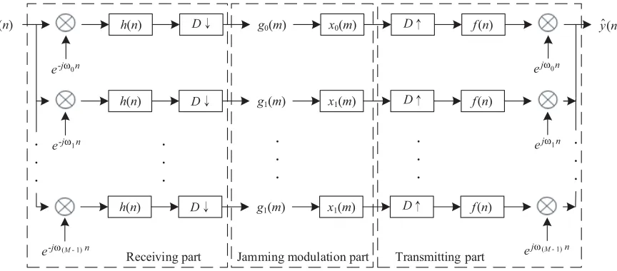
Digital channelized jamming system consists of three parts — receiving part, transmitting part, and jamming modulation part. Receiving and transmitting parts are digital channelization based, as described in Figure 1. Here, s(n) is the radar signal, and ˆy(n) is the jamming signal. ⊗ represents the convolution operator. The bandwidth of each subchannel is 2Mπ, whereM is the subchannel number. ωk is the center frequency of the kth (k= 0,1, ..., M −1) subchannel. h(n) and f(n) are the analysis filter and synthesis filter, respectively. Generally, h(n) =f(n). (·)↓represents the downsampling while (·)↑ denotes the signal interpolation. D is the down sampling rate. gk(m) is the down-sampled signal of the kth (k= 0,1, ..., M −1) subchannel, and xk(m) is modulation function of the corresponding subchannel.
s(n) h(n) g0(m) x0(m) f(n)
h(n) g1(m) x1(m) f(n)
h(n) g1(m) x1(m) f(n)
Receiving part Jamming modulation part Transmitting part
D→
D→
D→
D →
D →
D →
yˆ(n)
e-jω 0n
e-jω 1n
e-jω (M - 1)n
ejω 0n
ejω 1n
ejω (M - 1)n
Figure 1. The block diagram of digital channelized jamming system.
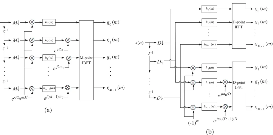
The key technologies are channelized receiving and transmitting. In this paper, digital channelization structure based on polyphase digital Fourier transform (PDFT) filter is adopted. The structures can be classified according to the subchannel numberM and the subchannel down sampling
rate D. D=M and D=M/2 are two common cases [21]. Figure 2 depicts the two structures of the
receiving system. Correspondingly, those of the transmitting system are shown in Figure 3.
For simplicity, the structure on condition ofD=M is adopted in this paper. The Fourier transform
of ˆy(n) is given as [22, 23]
ˆ
Y(ω) =S(ω)T0(ω) +
D−1
p=1
z z z (a) (b) M-point IDFT D-point IFFT D-point IFFT s(n)
-1 -1 -1 D→ D→ D→ M→ M→ M→ M→ e-jω 0mM
h (m)
h (m)
h (m)
h (m)
0
1
2
M - 1
g (m)
g (m)
g (m)
g (m) 0
1
2
M - 1 ejω 0
ej2ω 0
ej(M - 1)ω 0
s(n)
z-1
z-1
(-1)m
h (m)
h (m)
h (m)
0
1
D - 1
h (m)
h (m)
h (m)
0
1
D - 1
ejω 0/D
ejω 0(D - 1)/D
g (m)
g (m)
g (m) 0
2
M - 2
g (m)
g (m)
g (m) 1
3
M - 1
Figure 2. Implementation of PDFT architecture of receiving system when (a) D = M and (b)
D=M/2.
0 (a) (b) Σ Σ Σ Σ Σ y (m)
y (m)
y (m)
y (m) 0
1
2
M - 1
M-point IDFT D-point IFFT D-point IFFT ejω 0
ej2ω 0
ej(M - 1)ω 0
f (m)
f (m)
f (m)
f (m)
0
1
2
M - 1
f (m)
f (m)
f (m)
0
1
D - 1
f (m)
f (m)
f (m)
0
1
D - 1
ejω 0mM
yˆ(n) D → yˆ(n)
D → D → M → M → M → M → z-1 z-1 z-1 z-1 z-1 (-1)m ejω 0/D
ejω 0(D - 1)/D
y (m)
y (m)
y (m) 0
2
M - 2
y (m)
y (m)
y (m) 1
3
M - 1
Figure 3. Implementation of PDFT architecture of transmitting system when (a) D = M and (b)
D=M/2.
where Sp(ω) =S(ω−2Dπp). T0(ω) and Tp(ω) are the modulation function and aliasing error function, respectively, and defined as:
⎧ ⎪ ⎪ ⎪ ⎪ ⎪ ⎨ ⎪ ⎪ ⎪ ⎪ ⎪ ⎩
T0(ω) = 1 D
D−1
k=0
H(ω−ωk)F(ω−ωk)Xk(Dω−ωk)
Tp(ω) = 1 D
D−1
k=0
H
ω−ωk− 2πp
D
F(ω−ωk)Xk(Dω−ωk)
. (2)
simplicity, |H(ω)| = |F(ω)| = rect Δωω, where rect Δωω =
1, |ω| ≤Δω/2
0, |ω|>Δω/2 . To save resources and improve operational efficiency, the length ofxk(n) is 1.
Defining ˆYp(ω) = Sp(ω)Tp(ω), p = 0,1, . . . , D −1, we have ˆY(ω) = D− 1
p=0
ˆ
Yp(ω). When the radar
matched filter is fed by signal ˆYp(ω), the outputRp(ω) is given as
Rp(ω) = ˆYp(ω)·S∗(ω) =Sp(ω)·S∗(ω)·Tp(ω) (3) After inverse fast Fourier transform (IFFT),
rp(t) =
π
−πSp(ω)S
∗(ω)ejωtdω⊗t p(t) =
π
−πS
ω−2πp
D
S∗(ω)ejωtdω
⊗tp(t), (4)
whereS(ω) is the Fourier transform of s(t) =e−jπγt2, andS(ω−2πp/D) is that ofs(t)e−j2πBrp/Dt. So
π
−πS(ω−2πp/D)S∗(ω)ejωtdω=e−jπγ
Brp Dγ
2 δ
t−BDγrp
. Accordingly,
|rp(t)|=tp
t−Brp
Dγ
, (5)
which describes the amplitude relationship between radar range profile and digital channelized modulation function (whenp= 0) as well as aliasing error function (whenp >0).
3. SIDE-LOBE JAMMING
Generally, sidelobes inevitably arise with the use of filters. However, these sidelobes provide a new way for the active jamming based on digital channelization, which is studied in detail in this section.
3.1. Periodic Side-Lobe Jamming
When p= 0, Eq. (5) is recast in discrete form as
|r0(n)|=|t0(n)|=
D1h0(n)·x(n)M
, (6)
whereh0(n) =
π
−πH(ω)F(ω)ejωndω.
When the cutoff frequency ωc = εMπ (0< ε <1), the main lobe of h0(n) is enlarged. Thus some periodic components of x(n)M remain and form periodic false targets after range compression. In this case, the isolation between subchannels is higher, namely, the crosstalk Tp(ω) (p= 1,2, . . . , D−1) can be ignored.
Assume that the channelized filter is a rectangular window defined as
H(ω) =F(ω) =
1, |ω| ≤ωc
0, |ω|> ωc . (7)
Thus,
h0(n) =
sin (ωcn)
n . (8)
Substituting Eq. (8) into Eq. (6), we have
|r0(n)|= 1 D
sin (ωcn)
n ·x(n)M
. (9)
Assume x(n)M =
1, n=lM
0, n=lM , l = 0,±1,±2, . . .. It is found that when n = lM, l = 0 and ωcn = π2(2k−1), k = 0,±1,±2, ..., the side-lobe component arises. Contrariwise, the lth periodic component of x(n)M is suppressed at the zero point of sin(nωcn). When l = 0, r0(n) denotes the main lobe.
• The amplitude of thelth false target at cMl2fs, normalized with the main lobe, is|sinc(εl)|.
• The range between adjacent side-lobe false targets is proportional to sampling rate M, inversely proportional to subchannel numberfs, and unrelated to filter cutoff frequency ωc.
• The energy of side lobes concentrates as the subchannel numberMand cutoff frequencyωcincrease.
3.2. Shift-Side-Lobe Jamming
When p >0, Eq. (5) can be expressed in discrete form as:
|rp(n)|=tp(n)δ
n−Brpfs
Dγ
= 1
Dhp(n)·x(n)M ·δ
n−Brpfs
Dγ
, (10)
wherehp(n) =−ππH(ω−2pπ/D)F(ω)ejωndω.
When ωc = εMπ(ε >1), the energy of tp(n) increases, which spawns shift-side-lobe false targets in range profile. Meanwhile, the main lobe of h0(n) is so narrow that the periodic components of r0(n) = D1h0(n)·x(n)M are weakened seriously. Therefore, the error ofr0(n) can be overlooked.
Suppose that the channelized filter is a rectangular window defined as
H(ω) =F(ω) = ⎧ ⎨ ⎩
1, |ω| ≤επ D
0, |ω|> επ
D
. (11)
We have
hp(n) =
π
−πH(ω−2pπ/D)F(ω)e
jωndω= ε
π D
−επ D
H(ω−2pπ/D)ejωndω
= ⎧ ⎪ ⎨ ⎪ ⎩ επ D
(2p−ε)Dπ
ejωndω= 1
jne
jnεπ
D
1−ejn2Dπ(p−ε)
, p < ε
0, p≥ε
. (12)
Therefore,tp(n) can be written as
tp(n) = ⎧ ⎨ ⎩
1
jnDx(n)M ·e
jnεπ
D
1−ejn2Dπ(p−ε)
, p < ε
0, p≥ε
. (13)
Because ωc > Dπ, the main lobe width of hp(n) is smaller than M, which suppresses the periodic components of x(n)M, that is,hp(n)·x(n)M =hp(n)·x(n). Therefore, tp(n) can also be expressed as
tp(n) = ⎧ ⎨ ⎩
x(n)
jnD ·e
jnεπ
D
1−ejn2Dπ(p−ε)
, p < ε
0, p≥ε
(14)
Substituting Eq. (14) into Eq. (10), we have
|rp(n)|= ⎧ ⎪ ⎪ ⎨ ⎪ ⎪ ⎩ x
n−BDγrpfs
D·
n−BDγrpfs
1−ej2Dπ
n−BrpfsDγ (p−ε)
, p < ε
0, p≥ε
(15)
Similarly, when p < ε,
|rD−p(n)|=
x
n− Br(DDγ−p)fs
D·
n−Br(DDγ−p)fs
·1−ej2Dπ
n−Brp(DDγ−p)fs((D−p)−k)
(16)
|rp(n)|and|rD−p(n)|(p= 1,2, ...,ε−1 ) are the shift-side-lobe false targets in radar range profile, whereα is the largest integer less than or equal toα. Whenp= 0,r0(n) denotes the main lobe.
• There are 2ε−1 shift-side-lobe false targets in range compression output in total resulting from aliasing functiont1(n), tD−1(n), t2(n),tD−2(n), ..., tε−1(n), tD−ε−1(n).
• The positions of thepth and (D−p)th false targets are−B2Dγrpcand B2Dγrpc, respectively. The amplitude of those, normalized with the main lobe, is ε−εp, p= 1,2, ..., ε−1.
• The range between adjacent side-lobe false targets is inversely proportional to subchannel number
M, chirp rate γ, proportional to working bandwidth Br, and unrelated to filter cutoff frequency
ωc.
• The energy of shift-side lobes concentrates asεdeclines, and subchannel numberM grows.
4. EXPERIMENTS
In this section, to analyze the jamming performance and influencing factors to side-lobe jamming, some simulations are conducted based on simulated inverse synthetic aperture radar (ISAR) data. The radar parameters are listed in Table 1. For simplicity, finite impulse response (FIR) filters are adopted as analysis filter bank and integrated filter bank.
Table 1. Parameters for simulation.
Quantity Symbol Value Quantity Symbol Value
Pulse width Tp 10µs Input Jamming to Signal Ratio JSRin 20 dB
Bandwidth B 1 GHz Reference Range Rref 10 000 m
Radar Position O 0 m Carrier Frequency fc 10 GHz
Target Position OT 10 002 m PRI Ts 1 ms
4.1. Jamming Effect
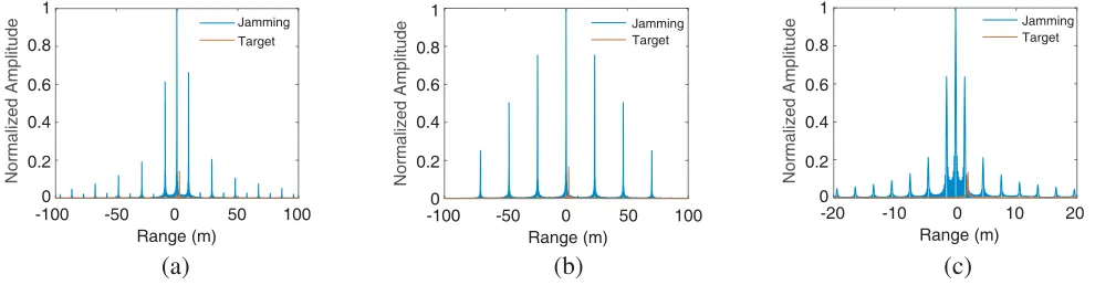
The pulse compression output of the side-lobe jamming, normalized with that of the main lobe, is illuminated in Figure 4(a) and Figure 4(b). The ISRJ jamming effect with the same JSRin is also presented in Figure 4(c) for comparison [11]. For convenience, the zero point of abscissa denotes reference point, where the preset false target is. For periodic side-lobe jamming shown in Figure 4(a), a train of false targets are symmetrically distributed in the radial distance, and their power decreases fast from the center to the edge, with several strong targets. The±2th and±4th false targets are suppressed because they meet the zero points of rectangular window. The output JSR is 16.96 dB. As for shift-side-lobe jamming shown in Figure 4(b), there are 6 shift-side-lobe false targets and a main-lobe one, whose JSR
Normalized Amplitude
(a) (b) (c)
-100 -50 0 50 100
Range (m)
-100 -50 0 50 100
Range (m)
-20 -10 0 10 20
Range (m) 1
0.8
0.6
0.4
0.2
0 Normalized Amplitude
1
0.8
0.6
0.4
0.2
0
Normalized Amplitude
1
0.8
0.6
0.4
0.2
0 Jamming
Target
Jamming Target
Jamming Target
is 15.55 dB. The power of them descends more mildly than periodic side-lobe jamming. In general, the periodic side-lobe jamming performs similarly with the ISRJ in jamming effect, while the former can produce false targets ahead of the real target much easier than the latter. Also, in jamming energy distribution, the shift-side-lobe jamming can build more effective false targets than ISRJ, which can only form 3–5 false targets.
4.2. Influencing Factors to Side-Lobe Jamming
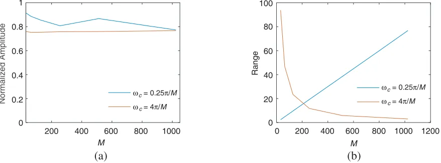
Figure 5 displays how the subchannel numberM influences the amplitude and position of side-lobe false targets. Overall,Mhas little influence on the amplitude, as shown in Figure 5(a). For periodic side-lobe jamming, some side-lobe false echoes are suppressed as long as they meet the zero points of the filter. Accordingly, the others are enhanced due to the energy conservation. This explains the ripples on the blue line in Figure 5(a). As for the distance distribution shown in Figure 5(b), the range between the two adjacent false targets increases in direct proportion toM in the case of periodic side-lobe jamming. However, it is in inverse proportion toM in the case of shift-side-lobe jamming.
Opposite to the subchannel number M, the cutoff frequency ωc mainly impacts the amplitude of side lobes reflecting the energy distribution among false targets and has almost no effect on the range
Normalized Amplitude
(a) (b)
1
0.8
0.6
0.4
0.2
0
200 400 600 800 1000
M
ω = 0.25π/M
ω = 4π/M
c
c
ω = 0.25π/M
ω = 4π/M
c
c
200 400 600 800 1000
M
0 1200
0 20 40 60 80 100
Range
Figure 5. The statistics of (a) the amplitude of the 1st side-lobe false target and (b) the distance between the adjacent false targets versus M.
(a) (b)
distribution, as depicted in Figure 6. For periodic side-lobe jamming, the amplitude of the side lobes normalized with the main lobe decreases with the increase of ωc, which is contrary to shift-side-lobe jamming. Generally speaking, the energy concentrates in the main-lobe false target as ωc goes away from Mπ. It is interesting that the relative amplitude of the pth (p= 1,2, ...,ε−1 ) side-lobe false target with ωc=εMπ is almost the same as that withωc = 1εMπ.
The position of the preset false target, denoted by R, the distance between the main lobe and the reference point, also influences the parameters of side-lobe jamming. Firstly, to ensure that the subchannel modulation function has a length of 1, the length of original modulation function is less than the subchannel number, that is,
|R|·fs
c
< M6 . Then, the symmetry of side-lobe jamming will be disrupted if R = 0, as described in Figure 7. For periodic side-lobe jamming, this mainly causes asymmetrical energy distribution, which can be explained by the filter mismatch. As for shift-side-lobe jamming, the nonzero R brings about irregular glitches among false echoes. The glitches share more energy as|R| grows. When
|R|·fs
c
> M3ε, the glitches are so high that the main lobe is hid.
The filter order and window type affect the filter sidelobes, in turn influencing the performance of side-lobe jamming. Figure 9 depicts how they affect the output JSR which reflects the energy distribution in a way. Normally, the higher the JSR is, the more the energy concentrates. For periodic side-lobe jamming, presented in Figure 8(a), whenN < M, JSR rises dramatically asN increases until it reaches its peak. For rectangular window, the peak appears atN =M. For Hamming and Blackman window, it appears at N = 2M. The main reason is that the energy concentrates on one point in these cases. After the peak, JSR decreases slowly because the rise of N leads to the drop of the filter side lobes. Then, when N > 10M, the side lobes fall to the bottom. Both the filter and the window
(a) (b) (c)
-100 -50 0 50 100
Range (m)
-100 -50 0 50 100
Range (m)
-100 -50 0 50 100
Range (m)
Normalized Amplitude
1
0.8
0.6
0.4
0.2
0
Normalized Amplitude
1
0.8
0.6
0.4
0.2
0
Normalized Amplitude
1
0.8
0.6
0.4
0.2
0
Figure 7. The outputs of side-lobe jamming withR= 0. (a)R=−2 m for periodic side-lobe jamming; (b)R= 1.5 m and (c) R=−3 m for shift-side-lobe jamming.
(a) (b)
(a) (b)
Figure 9. The MSE of the jamming output of the 10-bit quantified system for (a) periodic side-lobe jamming; (b) shift-side-lobe jamming.
type have little effect on the energy distribution. Figure 8(b) indicates that the JSR of shift-side-lobe jamming increases with the uptrend of N when N < M and becomes steady when N > M. The influence of the window type is also very little.
4.3. Quantization Analysis
To assess the physical achievability of the proposed jamming method, we analyze the jamming output of the 10-bit quantified jamming system and calculate its mean squared error (MSE) displayed in Figure 9. Overall, the MSE is around 10−10and decreases as the cutoff frequencyωcapproaches Mπ. It is suggested that the side-lobe jamming can be realized on the field-programmable gate array (FPGA).
5. CONCLUSIONS
This paper proposes a novel jamming method, side-lobe jamming, based on the side lobes introduced by digital channelizing filter bank. Due to the flexibility of DRFM and DDS, the proposed method can produce a symmetrical/asymmetrical train of false targets around the preset decoy. On the other hand, the number of side-lobe false targets can be easily controlled, which can form dense false target jamming in case of necessity. The experimental results verify the effectiveness and physical achievability of this method. We will focus on building the jamming system based on FPGA in the following research.
REFERENCES
1. Michael, R. F. and R. Michael,Electronic Warfare for the Digitized Battlefield, London, UK, Artech House, 2001, ISBN: 978-1580532716.
2. Wu, X. F., D. H. Dai, X. S. Wang, and H. Z. Lu, “Review of synthetic aperture radar electronic countermeasures,” Signal Processing, Vol. 3, 424–435, 2010, doi: 10.3969/j.issn.1003-0530.2010.03.017.
3. Zhou, F., M. D. Xing, X. R. Bai, G. C. Sun, and Z. Bao, “Narrow-band interference suppression for SAR based on complex empirical mode decomposition,” IEEE Trans. Geosci. Remote Sens., Vol. 6, 423–427, 2009, doi: 10.1109/LGRS.2009.2015340.
5. Wang, R. J., B. Sun, X. Wang, and S. Y. Cheng, “Transmitting pulse encoding for beyond-PRT retransmitting deception jamming detection in spaceborne synthetic aperture radar (SAR),” Sensors, Vol. 18, No. 5, 1666, 2018, doi: 10.3390/s18051666.
6. Liu, Z., J. P. Sui, Z. H. Wei, and X. Li, “A sparse-driven anti-velocity deception jamming strategy based on pulse-doppler radar with random pulse initial phases,”Sensors, Vol. 18, No. 4, 1249, 2018, doi: 10.3390/s18041249.
7. Wang, R. J., J. Chen, X. Wang, and B. Sun, “High-performance anti-retransmission deception jamming utilizing range direction multiple input and multiple output (MIMO) synthetic aperture radar (SAR),”Sensors, Vol. 17, No. 1, 123, 2017, doi:10.3390/s17010123.
8. Berger, S., “Digital radio frequency memory linear range gate stealer spectrum,” IEEE Transactions on Aerospace and Electronic Systems, Vol. 39, No. 2, 725–735, 2003, doi: 10.1109/TAES.2003.1207279.
9. Adler, E. and E. Viverios, “Direct digital synthesis application for radar development,” IEEE Int. Radar Conf., Washington, DC, May 1995.
10. Lou, C. Y., J. L. Xu, and X. N. Yang,Software-defined Radio: Principles and Practice, Publishing House of Electronics Industry, Beijing, China, 2014, ISBN: 9787121236785.
11. Wang, X. S., J. C. Liu, W. M. Zhang, et al., “Mathematic principles of interrupted-sampling repeater jamming (ISRJ),”Science in China. Series F: Information Sciences, Vol. 50, No. 1, 113– 123, 2007, doi: 10.1007/s11432-007-2017-y.
12. Feng, D. J., L. T. Xu, X. Y. Pan, and X. S. Wang, “Jamming wideband radar using interrupted-sampling repeater,”IEEE Transactions on Aerospace and Electronic Systems, Vol. 53, No. 3, 1341– 1354, 2017, doi: 10.1109/TAES.2017.2670958.
13. Scafd, G., “Techniques employed in ESM receiving systems for signal detection, frequency measurement and direction finding in the 1 GHz to 20 GHz frequency range,” 4th European Microwave Conference, Montreux, Switzerland, September 1974.
14. Hofmann, C. B. and A. R. Baron, “Wideband ESM receiving systems. II,” Microwave Journal, Vol. 24, 57–61, 1981.
15. Allen, D. E., “Channelised receiver — A viable solution for EW and ESM systems,” Communications, Radar and Signal Processing, IEE Proceedings F, Vol. 129, No. 3, 172–179, 1982, doi: 10.1049/ip-f-1:19820026.
16. Chen, X., A. Augusto, C. Domenico, et al., “Robust waveform and filter bank design of polarimetric radar,” IEEE Transactions on Aerospace and Electronic Systems, Vol. 53, No. 1, 370–384, 2017, doi: 10.1109/TAES.2017.2650619.
17. Wang, H., Y. Lu, and X. Wang, “Channelized receiver with WOLA filterbank,” 2006 CIE International Conference on Radar, Shanghai, China, October 2006.
18. James, T.,Digital Techniques for Wideband Receivers, Artech House, Norwood, USA, 1995, ISBN: 9780890068083.
19. Zhu, X., “A new wideband digital receiver and parameter estimation of pulse compression radar signals,” Harbin Engineering University, Harbin, China, 2008.
20. Daniel, R. Z., L. S. David, and W. F. Timothy, “A hardware-efficient multirate, digital channelized receiver architecture,” IEEE Transactions on Aerospace and Electronic Systems, Vol. 34, No. 1, 137–147, 1998, doi: 10.1109/7.640270.
21. Gong, S. X., “Research of active jamming technology and ECCM for wideband LFM radar,” National University of Defense Technology, Changsha, China, 2015.
22. Wu, C. Z. and K. L. Teo, “Design of discrete Fourier transform modulated filter bank with sharp transition band,” IET Signal Processing, Vol. 5, No. 4, 433–440, 2011, doi: 10.1049/iet-spr.2009.0269.