R E V I E W
Open Access
Analysis of cooperative jamming against
pulse compression radar based on CFAR
Xiang Liu
*and Dongsheng Li
Abstract
One important issue in radar jamming is the effect of inaccuracies in the radar position, which leads to a number of false targets entering the reference window of the constant false alarm ratio (CFAR) detector to reduce greatly. In this paper, two cooperative jamming methods specifically developed for a pulse compression radar with a CFAR detector are proposed with the aim of increasing the number of false targets when there is uncertainty regarding the radar position. First, several key parameters of the false targets are derived based on the principle of CFAR detection. Then, the principle, which takes advantage of two cooperative jamming methods to achieve a distribution of multiple false targets, is described. Finally, the influence of radar’s uncertain position on the two cooperative jamming methods is simulated and analyzed in detail. The simulation result shows that both jamming methods can effectively reduce the radar’s recognition rate, but there is a large difference when different interference modes are used by jammers. The obtained conclusion provides guidance for the practical application of cooperative jamming against pulse compression radar.
Keywords:Constant false alarm rate detection, Cooperative jamming, Pulse compression radar, Radar uncertain position
1 Introduction
In radar detection, the returned signals from radar tar-gets are often buried in nonstationary noise, clutter, and interference. Classical detection using a fixed threshold is no longer applicable due to the nonstationary nature of the background. To obtain a predictable and consist-ent performance, a radar system designer usually prefers a constant false alarm rate (CFAR) [1].
Two of the major CFAR detectors are the cell aver-aging (CA) CFAR and the orderly statistics (OS) CFAR [2]. The first detector (CA-CFAR) is the optimum CFAR processor in a homogeneous background, but it has se-verely degraded performance on the clutter edge and with interfering targets’ echoes [3, 4]. Hence, the OS-CFAR has been proposed to alleviate the problem
caused by a nonhomogeneous background [5]. The
OS-CFAR trades a small loss in detection performance relative to the CA-CFAR in ideal conditions for much less performance degradation in non-ideal conditions; this trade has been simulated by Blake [6].
A detector, especially an OS-CFAR detector, has a very strong anti-interference capability, which causes significant issues for the interferer [1,2]. Methods for deceiving pulse compression radar equipped with a CFAR detector have received increased attention in the recent past. The impact of interrupted-sampling repeater jamming on a radar using constant false alarm rate detection was analyzed in [7]. Specifically, the detection costs of CA-CFAR, OS-CFAR, and censored mean lever detector (CMLD) CFAR detec-tors for active decoy using jamming were analyzed. To evaluate the radar detection performance in a situation with multiple false targets, Fang et al. [8] analyzed typical CFAR detectors in an interfering target background. Un-fortunately, specialized jamming methods against CFAR detectors were not proposed in [7] or [8]. To solve this problem, a multiple-false-target jamming method against a linear frequency modulation (LFM) pulse compression radar with a mean level (ML) CFAR detector was proposed in [9,10]. Most of the mentioned studies have focused on CA-CFAR detectors. There are currently few specialized jamming techniques for OS-CFAR detectors, which are designed for multiple false targets.
* Correspondence:[email protected]
College of Electronic Engineering, National University of Defense Technology, No. 460, Huang Shan Road, Shu Shan District, Hefei, Anhui, People’s Republic of China
Radar jamming technology is in high demand because it is indispensable for counteracting the pulse compres-sion gain of the victim radars. As a result, the radar pa-rameters and the environment are often idealized during the process of jamming research. In fact, it is inevitable that there is an uncertainty in the radar position, which is obtained through electronic reconnaissance. The number of false targets entering the reference window of the CFAR detector is greatly reduced when there are in-accuracies in the radar position. At this time, the signifi-cant disadvantage of jamming generated by a single jammer is revealed. Existing ECMs are mostly classified into barrage jamming and deception jamming. Noise barrage jamming is not sensitive to the radar’s uncertain position, but it is difficult for noise barrage jamming generated by a single jammer to obtain an effective pulse compression gain in the pulse compression radar [11]. Additionally, it is necessary to add the number of the jammers to increase the power of noise barrage jam-ming. Coherent deception jamming based on DRFM can achieve a high pulse compression gain [12], but it is sen-sitive to the radar’s uncertain position. According to the law of conservation of energy, simply increasing the number of false targets with a single jammer will cause a decrease in the jamming power. To increase the number of false targets, cooperative jamming generated by mul-tiple jammers is required.
Cooperative jamming is a cooperative countermeasure technology. It was developed based on UAV airborne jammers, missiles, or balloon-borne jammers. Since 2000, the Defense Advanced Research Projects Agency (DARPA) has successively proposed low-cost UAV clus-tering technologies (LOCUST), such as Wolfpack elec-tronic warfare technology [13], the Gremlins programme [14], and offensive swarm-enabled tactics (OFFSET) [15]. The key technologies, such as an unmanned cluster self-organizing network, formation control, and launch recycling, have been demonstrated by DARPA, the US Air Force Research Laboratory (AFRL), and the US De-partment of Defense (DoD) [16], thus providing techno-logical support for cooperative jamming. Currently, research on cooperative jamming is mainly focused on
two aspects: multi-UAV phantom tracks and
multi-jammer power partitioning. Some initial concepts for generating coherent radar phantom tracks using co-operating vehicles were introduced in [17]. Subse-quently, the flyable ranges for an ECAV for the same class of phantom tracks were developed by Purvis et al. [18] and generalized bounds were presented for initial conditions. Recently, an optimal ECAV and coherent phantom track mission were designed considering high dimensionality and geometric constraints [19]. To solve the power partitioning problem for cooperative elec-tronic jamming, a simulated annealing algorithm (SA)
[20], two-person zero-sum game theory (TPZS) [21], and improved genetic algorithms (IGA) [22] have been proposed to distribute jamming power to radars. A co-herent phantom track is another active area of coopera-tive jamming research [23,24].
Based on the previous analysis, most cooperative jam-ming studies focus on the resource allocation problem, but there is currently little specialized analysis for co-operative jamming against pulse compression radar based on CFAR. Considering the fact that there is a radar uncertain position in practice, we propose two co-operative jamming methods specifically for pulse com-pression radar with a CFAR detector. Subsequently, the key parameters, such as the number and the power of the false targets, are derived based on the detection principle of the CFAR. In the simulation section, the performances of different interference modes in the CA-CFAR and OS-CFAR are analyzed when there is un-certainty in the radar position. Then, the required power or number of the cooperative jamming is calculated.
The contributions of the paper can be summarized as:
(1) We propose two cooperative jamming methods specifically for the pulse compression radar with a CFAR detector.
(2) We consider the effect of radar position
inaccuracies on radar jamming and calculate the required power or amount of cooperative jamming with the presence of a radar uncertain position. (3) Performances of cooperative jamming with different
interference modes in CFAR, especially in OS-CFAR, are analyzed. The obtained conclusion pro-vides guidance for the practical application of co-operative jamming against pulse compression radar.
The remainder of the paper is organized as follows. First, the model of the CFAR detection is deduced based on cooperative jamming. In Section 2, according to the definition and classification of cooperative jamming, two methods of generating cooperative jamming are pro-posed. In Section3, a theoretical analysis and computer simulation justify the methods’validity and efficiency. Fi-nally, Section4concludes the paper.
2 Model description
2.1 Analysis of OS-CFAR processors
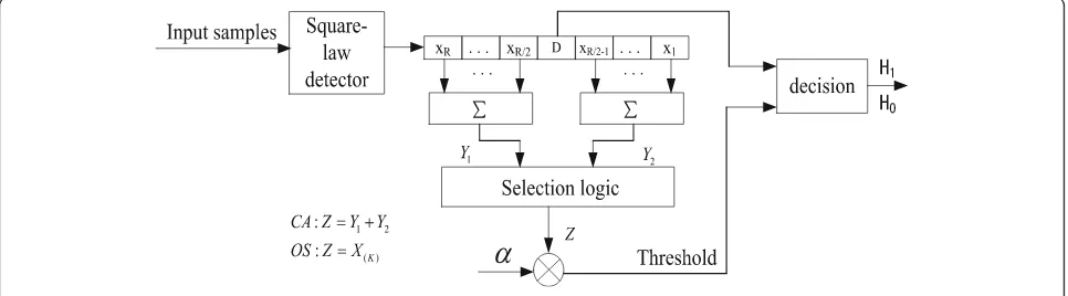
paper are shown in Fig. 1. Two reference windows (Y1, Y2) are formed from the sum of R/2 cell outputs on the leading and lagging side of the test cell. The output of the selection logic is the sum of the two window outputs
in the CA-CFAR, and the kth largest output in the
OS-CFAR.
In a general CFAR detection scheme, the square-law de-tected video range samples are sent serially into a shift register of lengthR+ 1 as shown inFig. l. The statisticZ, which is proportional to the estimate of noise or the inter-ference target power, is formed by processing the contents ofRreference cells surrounding the test cell containingD. A target is declared to be present ifDexceeds the thresh-oldαZ. Here,αis a constant scale factor used to achieve a desired constant false alarm probability for a given window of sizeRwhen the total background noise is homogeneous. From [1, 2], the false alarm probabilities of the CA-CFAR and OS-CFAR in a homogeneous background can be written as
PFA;CA¼ð1þαÞ−R ð1Þ
ln PFA;OS
¼ fðα;R;KÞ−fð0;R;KÞ ð2Þ
The variable K is the rank of the cell whose input is selected to determine the threshold of the OS-CFAR. According to [25], the following function is defined
fðα;R;KÞ ¼ ln ðR−KþαÞ! Rþα ð Þ!
≈ðαþR−Kþ1=2ÞlnðαþR−KÞ
−ðαþRþ1=2ÞlnðαþRÞ þ K
12ðαþR−KÞðαþRÞþK
ð3Þ
Similarly, the detection probabilities of the CA-CFAR and OS-CFAR as a function of the signal-to-noise ratio (SNR) can be written as
PD;CA¼ð1þαDÞ−R ð4Þ
ln PD;OS
¼ fðαD;R;KÞ−fð0;R;KÞ ð5Þ
where
αD¼α=ð1þSNRÞ ð6Þ
Assuming there are runits in the reference cells occu-pied by the interference targets, the presence of interfering target returns among the reference cells raises the thresh-old and the detection of the primary target becomes ser-iously degraded. According to (1) and (2), the new false alarm probabilities of the CA-CFAR and OS-CFAR in a multiple-false-target background can be written as
PJ;FA;CA¼ð1þαÞ−r 1þ1þαχ j
!r−R
ð7Þ
ln PJ;FA;OS
¼ f α 1þχjK
;R;K
−fð0;R;KÞ ð8Þ
where χj is the average interference-to-noise ratio (INR) of the false targets among the CA-CFAR reference cells and χjK is the INR of the kth largest output of the OS-CFAR. Similarly, according to (4) and (5), the new detec-tion probabilities of the CA-CFAR and OS-CFAR are obtained by replacingαwithαD. Thus
PJ;D;CA¼ 1þαD 1þχj
−r
1þαD
ð Þr−R ð9Þ
ln PJ;D;OS
¼f αD 1þχjK
;R;K
−fð0;R;KÞ
ð10Þ
2.2 The jamming parameters setting requirements In a homogeneous environment, only the noise inside the radar receiver is considered. According to the radar equation, the SNR of the target can be calculated as
SNR¼ PtGtGrλ the radar antenna transmission and reception gains, re-spectively, λ is the radar signal wavelength,σ is the
tar-get RCS, D is the pulse compression ratio, Rt is the
distance from the radar to the target,kis the Boltzmann constant,T0is the effective noise temperature, Brand F are the receiver bandwidth and noise figures, respect-ively, andLtis the radar feeders and atmospheric losses.
It is assumed that the jammers are independent of one another and that the interference signal powers are linearly superimposed at the radar receiver. According to the jam-ming equation in [22], the total INR can be calculated as
χj¼
wherePjiis theith jammer transmission power,Rjiis the
distance from the radar to the ith jammer, γji is the
polarization mismatch factor, and Lji contains jammer
feeders and atmospheric losses, etc., Gji is the jammer antenna transmission gain,Gri(θi) is the gain of the radar antenna on theith jammer, andGri(θi) can be calculated by the following empirical formula
Grð Þ ¼θi
whereθi0.5 is the radar half-power beam width andθiis the angle between theith jammer and the line from the radar to the target.K1is a constant, which for high-gain antennas generally has a value from 0.07 to 0.10, and for low-gain antennas the value ranges from 0.04 to 0.06.
For the given false probability and detector parame-ters in (6)–(10), in order to reduce the radar detection probability to a pre-set value, the INR in (12) must meet certain requirements. It can be seen from (12) that the INR is mainly affected by the number of jam-mers, the transmitted power, and the matched gain of the interference signals, which can be achieved by selecting different interference coordination methods and interference modes.
According to the above concepts, the steps for setting the jammers’parameters can be derived as follows:
Step 1. Calculate the SNR of the target echo via (11) with the assumption that the radar parameters have been detected.
Step 2. Calculate the INR under two detection modes via (6)–(10). In this step, it is assumed that the false alarm probability, the pre-set minimum detection prob-ability, and the detector parameters are known.
Step 3. Calculate the number of jammers, the transmitted power, and the matched gain of the interference signals in (12) by selecting different interference coordination methods and interference modes.
Figure2shows the block diagram of the above steps.
3 Cooperative jamming
Cooperative jamming is an efficient interference method for the target, in which multiple jammers are organized to work together in a certain pattern [26]. According to the different situations in a cooperative jamming implementation strategy, cooperative jamming can be divided into power-cooperative jamming and time-cooperative jamming.
Cooperative jamming is generally generated by
small-scale jammers, which have limited power. There will be a radar uncertain position in the actual interference process. From the previous analysis, jamming against pulse compression radar with a single jammer has a significant disadvantage when there is radar position inaccuracy. In
this case, multiple jammers are required to implement bar-rage jamming on the same area to increase the barbar-rage power. The kind of cooperative interference mentioned above is called power-cooperative jamming.
Modern radars generally have characteristics such as a multi-beam, wide frequency band, and high power, with an-tennas that can simultaneously scan large areas of airspace. Therefore, multiple jammers need to consider the time-cooperative jamming problem in adjacent areas. The multi-directional false targets generated by electronic com-bat air vehicles in different airspaces and at different azi-muths make it difficult for radar systems to detect real targets in the cover corridor. From the above analysis, it can be concluded that the goal of time-cooperative jamming is to increase the total interference time to increase the inter-ference barrage area during the entire interinter-ference process.
3.1 Power-cooperative jamming
Power-cooperative jamming generated by two jammers is shown in Fig.3, when there is a radar uncertain position.
It can be seen from (12) that χj is mainly affected by the jammers’transmitter power and the matched gain of the jamming signals. It is generally believed that the transmitter power is fixed after the type of jammer to be used is determined. The following content mainly ana-lyzes the matched gains of different interference modes after being matched by radar and considers the influence of different interference modes on the radar detection probability when a position error is involved.
The pulse compression gains of common interference modes are not analyzed in this paper because of limited space. For a detailed analysis, one can refer to [22, 27]. This article only lists the results in Table1.
Referring to Table1, noise frequency modulation jam-ming generally has a large barrage range for radar. In the presence of a radar uncertain position, the interfer-ence signal can also cover the referinterfer-ence window of the radar’s CFAR detector, but the interference signal power
is small. In this situation, increasing the number of jam-mers in the radar main lobe increases the interference power, so the probability of radar detection is reduced.
For smart noise convolution jamming, the longer the noise duration is, the greater the barrage range for the radar and the smaller the pulse compression gain. Simi-lar to noise frequency modulation jamming, smart noise convolution jamming is insensitive to radar uncertain position. To maintain the balance between noise power and barrage range, we can increase the INR by increas-ing the number of jammers when the noise duration is large. When the noise duration is small, the position of the jammer can be adjusted to compensate for the lack of interference barrage range.
Due to the time-frequency coupling of LFM signals, interrupted-sampling and periodic repeater jamming can be regarded as types of interference that are sent back to the radar with different time delays. The number of pri-mary false targets generated by interrupted-sampling and periodic repeater jamming is not only related to the pulse width but also related to the sampling duration and the transmitting duration. The following presents a detailed analysis of this issue.
Assume that the number of false targets generated by the jammer is M, the interval of the false targets is the same Δd, and the barrage range of interference is ΔD = (M−1)Δd. Assume that the radar uncertain position is
Fig. 3Power-cooperative jamming generated by two jammers
Table 1The pulse compression gains of different interference modes
Jamming modes Pulse compression gains
Noise frequency modulation jamming Tn/Tn+T
Smart noise convolution jamming Tn+T/Tn+ 1/B
Interrupted-sampling and periodic repeater jamming
η2BT
Δr, and the length of the reference cell is L. From the analysis in Section 2.1, we know that a CA-CFAR de-tector is sensitive to the number of false targets. The change in the number of false targets in the reference window will have a significant impact on the CA-CFAR detector. According to [6], the performance of the OS-CFAR detector degrades rapidly when the number of false targets in the reference cells satisfiesM≥R−K. The impact of the false targets on the two detectors is analyzed with the change in the barrage rangeΔDwhen there is a radar uncertain position.
Case 1:ΔD≥(R+ 1)L+Δr
In this case, the radar uncertain position does not affect the number of false targets in the reference win-dow and does not affect the detection result of the two detectors.
Case 2: (R+ 1)L≤ΔD≤(R+ 1)L+Δr
When Δr≤ΔD−(R+ 1)L, the radar uncertain position does not affect the number of false targets in the refer-ence window, which has no effect on the detection result of the two detectors.
As the radar uncertain position increases toΔD−(R+ 1)L<Δr≤ΔD−(R+ 1)L+ (M−1−(R−K))Δd, the num-ber of false targets in the reference window decreases by ceilðΔr−ΔDΔdþðRþ1ÞLþ1Þ. ceil(•) means rounding up to the nearest integer. In this case, only the detection probabil-ity of the CA-CFAR detector will decrease.
When Δr>ΔD−(R+ 1)L+ (M−1−(R−K))Δd, the number of false targets in the reference window is less than R−K, and the detection probability of the two de-tectors will decrease.
Case 3:ΔD≤(R+ 1)L
When Δr≤(R+ 1)L−ΔD, the position error does not affect the number of false targets in the reference win-dow, which has no effect on the detection result of the two detectors.
As the radar uncertain position increases to (R+ 1)L
−ΔD<Δr≤(R+ 1)L−ΔD+ (M−1−(R−K))Δd, the
number of false targets in the reference window will de-crease. In this case, only the detection probability of the CA-CFAR detector will decrease.
As Δr> (R+ 1)L−ΔD+ (M−1−(R−K))Δd, the num-ber of false targets in the reference window is less than R−K, and the detection probability of the two detectors will decrease.
For case 2 and case 3, the position of one of the jammers can be used as a reference, and the number of false targets in the reference window can be increased by adjusting the distance of the other jammers. The maximum coverage of the false targets generated by multiple jammers is
ΔDmax¼
Xn
i¼1
MiΔdi ð14Þ
3.2 Time-cooperative jamming
It is difficult for a jammer to deceive radar in real time due to the fast scanning speed of the radar antenna. To increase the distribution range of the false targets in the airspace during radar scanning, the airspace position of the jammers should be reasonably arranged, and the total interference time can be increased to achieve the purpose of time-cooperative jamming.
Time-cooperative jamming can be divided into time-syn-chronized cooperative jamming and time-circulating co-operative jamming according to the different interference durations of each jammer. Time-synchronized cooperative jamming means that the radar would be simultaneously deceived by each jammer during the penetration process. Time-circulating cooperative jamming refers to the jam-ming mode in which the radar would be deceived by each jammer in turn, and the interference formed at the radar spans the entire jamming period. The jammer is turned on to deceive the radar when the protected target reaches the vicinity of the jammer.
It can therefore be seen that the analysis of the time-circulating cooperative jamming is similar to the
power-cooperative jamming when the entire time-circulat-ing cooperative jammtime-circulat-ing process is divided. Therefore, this paper mainly discusses selection of the jamming pa-rameters and the radar’s detection performance when using time-synchronized cooperative jamming.
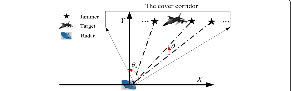
Time-synchronized cooperative jamming generated by multiple jammers is shown in Fig.4.
In Fig. 4, θa is the target’s azimuth angle in the cover corridor.θiis the azimuth difference between theith jam-mer and thei+ 1th jammer. The distance difference from theith jammer to thei+ 1th jammer can be calculated as
Si;iþ1¼
ffiffiffiffiffiffiffiffiffiffiffiffiffiffiffiffiffiffiffiffiffiffiffiffiffiffiffiffiffiffiffiffiffiffiffiffiffiffiffiffiffiffiffiffiffiffiffiffiffiffiffiffi
R2
i þR2iþ1−2RiRiþ1 cosð Þθi
q
ð15Þ
whereRiandRi+ 1are the distances from theith andi+ 1th jammers to the radar, respectively. It is assumed that the radar’s half-power beam width is θi0.5in order to en-sure that at least one jammer exists in each of the radar’s beam widths. That is,θi≤θi0.5, the distance from theith jammer to thei+ 1th jammer needs to be satisfied
Si;iþ1≤Si;iþ1 maxð Þ¼
ffiffiffiffiffiffiffiffiffiffiffiffiffiffiffiffiffiffiffiffiffiffiffiffiffiffiffiffiffiffiffiffiffiffiffiffiffiffiffiffiffiffiffiffiffiffiffiffiffiffiffiffiffiffiffiffiffi
R2
i þR2iþ1−2RiRiþ1cosðθi0:5Þ
q
ð16Þ
When θi=θi0.5, the specific value of the jammer spa-cing mainly depends on the position and shape of the cover corridor.
Based on the azimuth angle, the expression of the jam-mers’number can be further deduced as
num¼ceil θθa
i ≥ceil
θa
θi0:5
ð17Þ
4 Simulation results and discussion 4.1 Analysis of two detectors’detection in a homogeneous environment
According to (1), Table2 lists the required scaling factor
α to obtain PFA, CA and R as the parameters of the CA-CFAR.
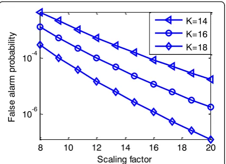
According to (3) and (6), Fig.5lists the required scal-ing factorαwhenR= 24 for the OS-CFAR.
The behavior of the scaling factor α of the
OS-CFAR detector is presented here as a function of
K as shown in Fig. 5. The curves are parametric in
the false alarm probability PFA, OS. We can see that
the scaling factor α increases as PFA, OS decreases.
The dip in the false alarm probability PFA, OS is
caused by an increase in the scaling factor α and the parameter K.
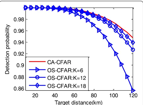
In a homogeneous environment, according to (4)–(6), when the false alarm probability PFA= 10−6, R= 24. The performances of both CFAR systems are presented in Fig.6with differentKand SNR values.
The detection characteristics of the OS-CFAR de-tector as a function of the primary target SNR, the rank of the cell (K= 6, 12, 18), and the results are
shown in Fig. 6. For comparison, the CA-CFAR
re-sults are also shown in the same figure. Obviously, the CA-CFAR detector has the largest detection
prob-ability at any SNR censoring value. Thus, the
CA-CFAR detector has better performance relative to the OS-CFAR detector when the noise background is homogeneous.
Table 2Scaling factorαfor CA-CFAR withPFA,CAandR
PFA,CA R= 8 R= 16 R= 24 R= 32
10−4 2.162 0.778 0.468 0.334
10−6 4.623 1.371 0.778 0.540
10−8 9.000 2.162 1.154 0.778
Fig. 5Variation of the scaling factorα
4.2 Analysis of two detectors’detection in power-cooperative jamming
In this section, it is assumed that the enemy radar parame-ters have been accurately detected. The pulse compression radar’s parameters in (11) are used, where Pt= 1.5 MW, Gt=Gr= 30 dB, λ= 0.1 m, T= 50 μs, B= 10 MHz,
σ= 6 m2, T0= 290 K, F= 3 dB, andLt= 6 dB.
It is assumed that the initial distance between the radar and the target Rt= 120 km and that the radar is interfered by two identical jammers. The two jammers arrive at the enemy radar with the target from far to near using the jammers’ parameters in (12), whereGj= 10 dB,Lj= 10 dB,γj= 10 dB, andPj= 100 W.
It is assumed that the number of the two detectors’ ref-erence cellsR= 24, the length of the reference cellL= 75 m, the probability of a false alarmPFA= 10−6, and the rank of the representative cell in OS-CFARK= 3/4R= 18.
In a homogeneous environment, Fig. 7 shows the
de-tection probability of the two detectors as a function of distance with differentKvalues.
In the following simulation, power-cooperative jamming would be generated by two jammers with the three interfer-ence modes in Table1. The analysis of power-cooperative jamming will be divided into three cases. In the first case, the two jammers transmit noise frequency modulation power-cooperative jamming signals. In the second case, the
two jammers transmit smart noise convolution
power-cooperative jamming signals. In the third case, the two jammers transmit interrupted-sampling and periodic repeater power-cooperative jamming signals.
Case 1: Noise frequency modulation power-cooperative jamming
Figure8shows the detection probability at different dis-tances with noise frequency modulation power-cooperative jamming for noise durations Tn= 10 μs and Tn= 20 μs. Comparing Fig. 8aand Fig. 8bwith Fig. 7, it can be seen that the noise FM interference improves the detection threshold, and the detection probability of the two detec-tors on the target are both reduced. However, noise frequency modulation power-cooperative jamming cannot achieve a coherent processing gain by the pulse compres-sion radar, and the probability of detection of the two detectors is still high. Therefore, it is necessary to increase
the number of jammers and the jammers’ power when
simply implementing noise frequency modulation power -cooperative jamming.
Case 2: Smart noise convolution power-cooperative jamming
Smart noise convolution power-cooperative jamming has both noise jamming and coherent jamming character-istics. Comparing the simulation results from case 1 and case 2, the smart noise convolution power-cooperative jamming has a better interference effect than the noise fre-quency modulation power-cooperative jamming for the same noise duration.
From the theoretical analysis in Table1, we know that the longer the noise duration of the smart noise convo-lution jamming is, the larger the barrage range of the Fig. 7Probability of detection for different distances without an
interfering target
(a) (b)
smart convolution jamming is to the radar, while the pulse compression gain is simultaneously reduced. The simulation results in Fig. 9a and Fig. 9b are consistent with the theoretical analysis.
Case 3: Interrupted-sampling and periodic repeater power-cooperative jamming
It is assumed that the sampling periods of the two jammers Ts= 10 μs, and the sampling time square τ and the repeater timeTr are each 1 μs. There will be M= 9 independent main false targets, because Tr> 2/ B= 0.2 μs. False target interval Δd=c⋅Tr/2 = 150 m, i.e., ΔD= 1200 m for the total false target distance, and (R+ 1)L= 25 × 75 = 1875 m in the total detector
distance, which belongs to case 3 in Section 3.1.
Assuming that the position error is large enough Δr = 1200 m > (R+ 1)L−ΔD+ (M−1−(R−K))Δd, the position error will affect the interference results of both detectors. At this time, two jammers are used for power coordination. According to (14), the max-imum coverage of the false targets generated by the two jammers ΔDmax= 2ΔD= 2400 m.
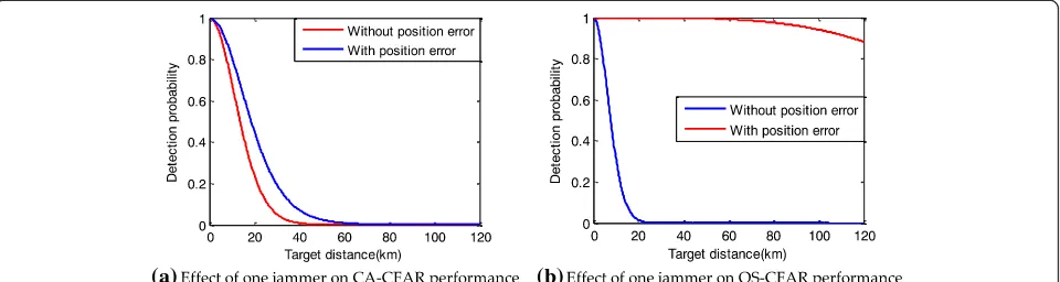
From the simulation results shown in Fig. 10a and
Fig.10b, it can be seen that the effect of one jammer on the two detectors’performances is inferior when there is an un-certain radar unun-certain position. However, it has a greater impact on the OS-CFAR, because the number of false tar-gets in the reference window is significantly less thanR-K.
Two detectors’ performance in the interfering targets generated by two jammers is shown in Fig.11.
From the results in Fig.11, it can be seen that the power coordination generated by two jammers can significantly reduce the detection probability of the two detectors. The number of false targets in the reference window is in-creased after interrupted-sampling and periodic repeater power-cooperative jamming is used, and the detection threshold is raised, which compensates for the influence of the radar uncertain position on the jamming.
4.3 Analysis of two detectors’detection for time-cooperative jamming
In this section, it is assumed that the target’s azimuth angle in the cover corridor isθa= 90°, the radar half-power beam
(a) (b)
Fig. 9Effect of smart noise convolution power-cooperative jamming on two detectors’performances.aNoise durationTn= 10 μs.bNoise durationTn= 20 μs
(a) (b)
Fig. 10Effect of one jammer on the detector’s performance with/without position error.aEffect of one jammer on CA-CFAR performance.
width is θi0.5= 2°, the target’s initial coordinates are (10 km, 17.32 km), the flying speed is (−200 m/s, 0 m/s), and the azimuth difference isθi=θi0.5= 2°. To ensure that there is only one jammer in the main lobe during radar scanning, the number of jammers num = 90/2 = 45 and the jammers are evenly distributed in the cover corridor. Because the effect of time-cooperative jamming on the two detectors is similar, taking into account the length of the paper, the simulation only uses the detection results of the OS-CFAR detector for illustration.
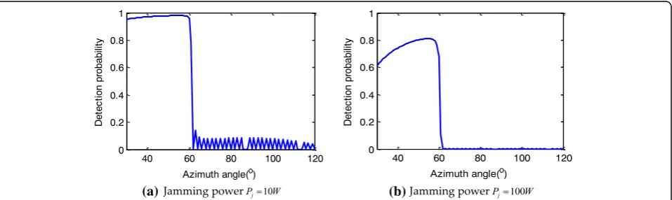
The jammer and OS-CFAR detector parameters are the same as in Section4.2, but the jamming power is dif-ferent, set at 10 W and 100 W, respectively.
Comparing the simulation results in Fig. 12, it can be seen that time-cooperative jamming is an effective method on the OS-CFAR detector. When the azimuth angle is less than 60°, the detection probability increases because the target flies towards the enemy radar, and the distance from the target to radar decreases, while most of the jammers are located far from the target. When the azimuth angle
reaches 60°, the target is just at the center of the cover cor-ridor. The gain of the radar antenna obtained by the jam-mer gradually reaches a maximum, and the detection probability of the OS-CFAR drops rapidly.
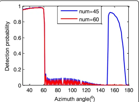
Figure 13 depicts the detection probability changes with different numbers of jammers: num = 20 and num = 60. When the number of jammers num = 20 is less than the design requirement in (17) of Section 3.2, the detection probability of the target will be less than 0.2 when flying in a short range in the center of the cover corridor.
Comparing Fig. 12a and Fig. 13b, it can be seen that an increase in the number of jammers does not signifi-cantly improve the jamming effect, and its greater role is to extend the length of the jamming cover corridor, which is shown in Fig.14.
Based on the above analysis, in order to increase the length of the jamming cover corridor, the number of jammers should be increased. Specifically, if the length of the cover corridor is fixed, taking the cost into con-sideration, the number of jammers should be
num¼ceilðθa=θi0:5Þ ð18Þ
5 Conclusions
In this paper, two cooperative jamming methods are pro-posed for CFAR detectors without certain radar position information. First, several key parameters of the false targets are derived based on the principle of CFAR de-tection. Then, the influence of different jammer interfer-ence modes on the radar detection probability is analyzed in detail.
For power-cooperative jamming, noise frequency modulation and smart noise convolution power-co-operative jamming can more or less reduce the detection probabilities of CFAR detectors. Additionally, smart noise convolution power-cooperative jamming has a Fig. 11Effect of two jammers on the detector’s performance with
position error
(a) (b)
better interference effect than noise frequency modula-tion power-cooperative jamming for the same noise dur-ation. Interrupted-sampling and periodic repeater power -cooperative jamming can achieve a larger pulse com-pression gain than either of the two jamming methods mentioned above, but it is sensitive to the radar uncer-tain position. In summary, for power-cooperative jam-ming, noise barrage can be used to improve the noise floor and cooperate with deceptive jamming, i.e., interrupted-sampling and periodic repeater jamming, to accomplish power barrage.
With time-cooperative jamming, the number of jam-mers and their power can both influence the probabilities of CFAR detectors. The detection probabilities of the de-tectors both decrease as the number and power of jam-mers increase. When the target is just at the center of the cover corridor (the azimuth angle reaches 60° in the ex-ample shown in this paper), the detection probability of the detector drops rapidly. For time-cooperative jamming, the length of the cover corridor can be increased by in-creasing the number of jammers. If the length of the cover
corridor is fixed, in the interest of conserving resources, the number of jammers should beceil(θa/θi0.5).
Our future work is to use cooperation jamming to de-ceive a radar’s network. In particular, how to generate phantom tracks using a group of cooperating ECAVs should be considered, including the effect of radar pos-ition inaccuracies on the phantom track and the phan-tom track’s cooperation and geometric constraints.
Abbreviations
CA-CFAR:Cell averaging constant false alarm ratio; CFAR: Constant false alarm ratio; DRFM: Digital radio frequency memory; INR: Interference-to-noise ratio; LFM: Linear frequency modulation; ML-CFAR: Mean level constant false alarm ratio; OS-CFAR: Orderly statistics constant false alarm ratio; RCS: Radar cross section; SNR: Signal-to-noise ratio
Acknowledgements
The authors want to acknowledge the help of all the people who influenced the paper. Specifically, they want to acknowledge the editor and anonymous reviewers for their valuable comments.
Funding
There is no source of funding for this paper.
Availability of data and materials
Data sharing is not applicable to this article as no datasets were generated or analyzed during the current study.
Results and discussion section
Section 4 of the manuscript—Simulation results and discussion—can be seen as the combination of the results section and the discussion section.
Methods/experimental section
In this work, one important issue in radar jamming is the effect of inaccuracies in radar position, which leads to a greatly reduced number of false targets entering the reference window of the constant false alarm ratio (CFAR) detector. Therefore, two cooperative jamming methods specifically for the pulse compression radar with CFAR detector are proposed in this paper. We used MATLAB software on a computer to generate simulation data for experimenting according to the radar parameters described in the manuscript. We applied the proposed algorithm to the simulation data and analyzed the corresponding results. The theoretical analysis and computer simulation justify the methods’ validity and efficiency. The obtained conclusion has a certain guiding significance for the practical application of jamming against pulse compression radar.
(a) (b)
Fig. 13Detection probability changes with different numbers of jammers.aJamming number num = 20.bJamming number num = 60
Authors’contributions
XL is the primary author of this paper, who developed the simulations and wrote the first draft of the paper. DSL scientifically supervised the work and acted as his academic advisor through the duration, providing feedback at all levels. Both authors read and approved the final manuscript.
Ethics approval and consent to participate
Not applicable.
Competing interests
The authors declare that they have no competing interests.
Publisher’s Note
Springer Nature remains neutral with regard to jurisdictional claims in published maps and institutional affiliations.
Received: 26 April 2018 Accepted: 25 October 2018
References
1. M.A. Richards,Fundamentals of Radar Signal Processing(McGraw-Hill Professional Publishing, New York, 2005)
2. H. You, G. Jian, M.X. Wei,Radar Target Detection and CFAR Processing (Tsinghua University Press, Beijing, 2011)
3. Z. Messali, F. Soltani, Performance of distributed CFAR processors in Pearson distributed clutter. EURASIP J. Adv. Signal. Process.2007, 1–7 (2007) 4. N. Janatian, M.M. Hashemi, A. Sheikhi, CFAR detectors for MIMO radars.
Circuits Syst. Signal Process32(3), 1389–1418 (2013)
5. L. Kong, B. Wang, G. Cui, W. Yi, X. Yang, Performance prediction of OS-CFAR for generalized sterling-chi fluctuating targets. IEEE Trans. on Aerospace and Electronic Systems52(1), 492–500 (2016)
6. S. Blake, OS-CFAR theory for multiple targets and nonuniform cIutter. IEEE Trans. on Aerospace and Electronic Systems24(6), 785–790 (1988) 7. D.J. Feng, Y. Yang, L.T. Xu, Impact analysis of CFAR detection for active
decoy using interrupted-sampling repeater. J. China Univ. Defense Technol. 38(1), 63–68 (2016)
8. M.X. Fang, J.G. Wang, Y.J. Yang, Evaluation on netted radar detection performance in the distributed jamming of multi-false target. Mod. Def. Technol.42(3), 135–141 (2014)
9. L.F. Shi, Y. Zhou, D. LI, Multi-false-target jamming effects on the LFM pulsed radar’s CFAR detection. J. Syst. Eng. Electron.27(5), 818–822 (2005) 10. Y R Zhang, M G Gao, Y J Li, In Proceedings of 2014 IEEE 9th Conference on
Industrial Electronic and Application (ICIEA). Performance Analysis of the Mean Level CFAR Detector in the Interfering Target Background IEEE, (2014), pp.1045–1048
11. W. X S, L. J C, W.M. Zhang, Mathematic principles of interrupted-sampling repeater jamming. Sci. China Ser. F Inform. Sci.50(1), 113–123 (2007) 12. Z. S S, Z. L R, Discrimination of active false targets in multistatic radar using
spatial scattering properties. IET Radar, Sonar & Navig10(5), 816–826 (2016) 13. K. Chaisoon, DARPA issues wolfpack solicitation. J. Electron. Def.24(5), 16 (2001) 14. K. J, DARPA moves forward on plan to develop swarms of cooperating
drones. Military & Aerospace Electronics27(5), 4–6 (2016)
15. K. J, DARPA to develop swarming unmanned vehicles for better military reconnaissance. Military & Aerospace Electronics28(2), 4–6 (2017) 16. R. Scott, Unmanned upstart: Kratos casts off its cloak. Jane's International
Defense Review49, 36–39 (2016)
17. M. Pachter, P.R. Chandler, R.A. Larson, K.B. Purvis,Proceedings of AIAA Guidance, Navigation, and Control Conference and Exhibit. Concepts for Generating Coherent Radar Phantom Tracks Using Cooperating Vehicles AIAA (2004), pp. 1–14
18. B.P. Keith, P.R. Chandler, M. Pachter, Feasible flight paths for cooperative generation of a phantom radar track. J. Guid. Control Dynam.29(3), 653– 661 (2006)
19. I.I.H. Lee, H.A. Bang, A cooperative line-of-sight guidance law for a three-dimensional phantom track generation using unmanned aerial vehicles. J. Aerosp. Eng.227(6), 897–915 (2016)
20. L. Y A, N. T Q, et al., Application of simulated annealing algorithm in optimizing allocation of radar jamming resources. Syst. Eng. Electron.31(8), 1914–1300 (2009)
21. X M LI, T L Dong, G M Huang, Distribution method of jamming power to radar net based on two-person zero-sum game. J. Sichuan Univ., 48(3), 129–135 (2016)
22. Z. Y R, G. M G, L. H Y, L. Y J, Evaluation method of cooperative jamming effect on radar net based on detection probability. J. Syst. Eng. Electron.37, 1778–1786 (2015)
23. M. Pachter, P.R. Chandler, R.A. Larson, K.B. Purvis, inConcepts for Generating Coherent Radar Phantom Tracks Using Cooperating Vehicles AIAA. Proc. AIAA guidance, navigation, and control conference and exhibit, providence (2004), pp. 1–14
24. N. Dhananjay, D. Ghose, Generation of a class of proportional navigation guided interceptor phantom tracks. J. Guid. Control Dynam.38(11), 2206– 2214 (2015)
25. N. Levanon, Detection loss due to interfering targets in ordered statistics CFAR. IEEE Trans. Aerosp. Electron. Syst.24(6), 678–681 (1988)
26. Z. Y R, L. Y G, G. M G, Optimal assignment model and solution of cooperative jamming resources. J. Syst. Eng. Electron.36(9), 1744–1749 (2014)