Available online: https://edupediapublications.org/journals/index.php/IJR/ P a g e | 3057
Low Frequency Modular Multilevel Converter Topology for
Improved Dynamic Performance of Variable-Speed AC Drives
G. S. R. Ajay Krishna
& D. Krishna
1M.Tech Student, Department of EEE, Anurag Group of institutions, Hyderabad, India. 2Asst. Professor, Department of EEE, Anurag Group of institutions, Hyderabad, India.
Abstract—This paper presents a control arrangement for the modular multilevel converter (MMC) to drive a variable-speed alternating current machine, mainly concentrating on upgrading dynamic fruition. In a manner, the energy balance in the MMC cell capacitors is prone to be unstable at start-up and low-frequency operations. Moreover, the MMC topology fundamentally requires advanced control methodology to modify imperativeness and smother the voltage pulsation of each cell capacitor. This paper proposes a control system for the healthy dynamic response of MMC even at zero frequency using leg offset voltage injection. The leg offset voltage for changing the arm energy is made by direct calculation but not the circulating current control controller. With the help of the exceedingly capable leg offset voltage from facilitate calculation the dynamic performance of a MMC at low speeds has clearly made progress. The ac machine has been driven from zero to maximum speed without enormous cell capacitor voltage ripples with help of this strategy. The proliferation and trial verify that relentless operation is guaranteed down to <2% of the rated speed under disturbance of 40% step load torque.
Index Terms— Dynamic performance,inner circulating current, Arm energy balancing, modular multilevel converter (MMC), motor drive.
Superscript „∗‟
NOMENCLATURE Reference value.
Superscript „∼‟ Low-frequency component. Superscript „∧‟ High-frequency component. x -phase Representation of one of the u, v,
or w phases.
vxo Leg offset voltage of x -phase leg. vsn Common mode voltage.
ixo Circulating current of x -phase leg. ωs Three-phase output frequency. R Resistance of arm inductor. L Inductance of arm inductor. Ccell Capacitance of dc capacitor in
a sub module cell.
ExP Upper arm energy in x -phase leg.
ExN Lower arm energy in x -phase leg.
vxPiC i th cell capacitor voltage in upper arm in x -phase.
vxNiC i th cell capacitor voltage in lower arm in x -phase.
I. INTRODUCTION
A MODULAR multilevel converter (MMC) with concentrate on high-power medium voltage alternating current motor drives is conferred [1]–[10]. The usage of a MMC makes it possible to save gigantic parts in a medium-voltage motor drive application, for instance, a line-transformer, filter, and dc-link reactor. A differentiated and standard medium voltage source converter, the MMC has a specific structure made up of similar converter cells. Since it can give higher number of voltage level for medium voltage applications easily, the nature of the yield voltage waveform is better. Additionally, because of its structure it has purposes of enthusiasm, for instance, easy assembly and maintenance.
Figure. 1 demonstrates the circuit of a MMC. This topology should be controlled by additional control techniques. As demonstrated in Figure. 1, since the lower and upper arm currents flowing through cells, these arm currents cause pulsations of cell capacitor voltages. The pulsation of each cell‟s capacitor voltage is mainly affected by the output phase current and output frequency. Theoretically, the amount of the cell voltage fluctuation is proportional to amount of the output phase current and inversely proportional to working frequency [6]. Along these lines, remarkable effort is requested to drive the ac machine through MMC, which requires extensive starting torque and low-speed steady state operation. In late investigations of [7]–[9] and [16], the standards and calculations for alternating current motor drives with the MMC have been presented. In any case, they didn't address the real control procedures, for example, as, including standstill, changing output frequency and covering load torque disturbance.
Available online: https://edupediapublications.org/journals/index.php/IJR/ P a g e | 3058 help of PI controller or the proportional and resonant controller.
Fig.1. Circuit configuration of the MMC.
the execution of the circulating current controller has impact on the behavior of the balancing control. Therefore, to enhance the balancing performance by increasing bandwidth of the balancing controller, this paper proposes a balancing control method without the circulating current controller. In this way, in the view purpose of capacitor voltage adjusting, the offset leg voltage can be specifically gotten with no delay because of the circulating current controller. Along these lines, the data transfer capacity (bandwidth) of adjusting controller in light of the direct voltage injection technique can be enhanced more than that in view of the circulating current controller. Including, the dissimilarities between the cell voltages can be diminished quicker. Therefore, from the viewpoint of the control dynamics and control unpredictability, the proposed leg offset voltage injection strategy is preferable and more straightforward over the ordinary circulating current injection technique. Moreover, the leg offset voltage injection strategy with the high frequency can be enhanced more than that of current injection technique, due to the high frequency injection of the proposed technique. Consequently, attributable to the high-frequency injection with the strategy which is proposed, the variance of voltage in the cell capacitor can be within the limit compared with circulating current injection technique.
The target of this venture is to propose a control strategy for unrestricted frequency range operation along with zero speed for variable speed alternating current motor drive. The strategy which is proposed decreases the control execution
reduction of the MMC when the load torque suddenly changes. The control method introduces two modes of operation namely: 1) a low-frequency mode for zero and low-speed operation and 2) a normal frequency mode from normal to higher speed operation. The procedure in the low-frequency mode abuses offset leg voltage and common mode voltage with the high-frequency component to smother the cell capacitor voltage swell. The square wave voltage is utilized as the leg balance voltage, which makes the circulating current peak is compressed when correlated with sinusoidal voltage waveform [7]. A switchover approach between two modes of operation is depicted to drive the alternating current machine in the overall operating speed region.
To confirm the capability of the proposed control scheme, a 12-kV 24-MVA MMC-based variable speed motor drive system was designed using the MATLAB software. The results of the simulation could offer the possibility and favorable position of the contrived technique for high-power nominal voltage drives with MMC. Also, tests for variable-speed alternating current motor drives by a 10-kVA model MMC mirroring blowers, pump drive framework, or fans were executed to check the feasibleness of the proposed balancing strategy. The analyses were directed for looking at elements of the sinusoidal and square wave leg offset voltage. The steady operation at 1 Hz, which is <2% of the evaluated speed, is appeared under an unexpected step load torque from 0% to 40% to exhibit the dynamic execution. The experiment shows that all control procedures involved were very used in the variable-speed alternating current motor drive framework with a load where the torque deviate in corresponding to the square of the speed, similar to pumps, fans, or blowers.
II. CONFIGURATION AND BASIC PRINCIPLE OF THE MMC
Fig. 1(a) shows the circuit configuration of the MMC. The three-phase MMC is composed of three legs and each leg has two arms and has an inductor in each arm. Each arm has N -identical half-bridge cells with cascade connection, and each cell consists of two switches and a dc capacitor. The cascaded cell modules in detail are shown in Fig. 1(b). In Fig. 1(a),
i
xl andi
xuare the lower and upper arm currents, respectively, and
i
xs is the output phase current where x represents the u-, v -, or w-phase. The circulating current,i
x0 and output phase current,i
xs areAvailable online: https://edupediapublications.org/journals/index.php/IJR/ P a g e | 3059
i
xu= i
xu−
i
xl(1)
i
x0=
ixu+ixl2
(2)
i
xu=
12
𝑖
𝑥𝑠+ i
x0(3)
i
xl=
−
12
𝑖
𝑥𝑠+ i
x0(4)
The leg offset voltage,
v
x0, produces a circulatingcurrent defined as in (5), where R stand for the resistance and L stand for the inductance of an arm inductor when all the inductors in the arm of MMC are assumed to be identical. From the relationships of the voltages along the x -phase loop, the upper, and lower arm voltage references are denoted as (6) and (7), respectively, where
v
dc is the dc-link voltage, andv
xP is the upper arm voltage andv
xN is the lower arm voltage. The common mode voltage,v
sn , is the difference in voltage between nodes s‟ and n‟, andv
xs is the phase voltage, which isv
xs =v
mcos
(
ω
st)
. A detailed mathematical description of the relationships in an MMC is given in [10]v
x0= (R + L
d
dt
)i
x0(5)
v
xP∗=
Vdc2
−
v
xs∗
−
v
sn
∗
−
v
x0∗
(6)
v
xN∗=
Vdc2
+ v
xs∗
+ v
sn∗
−
v
x0∗(7)
The instantaneous power of each arm in the x -phase can be deduced as (8) and (9). These two equations must be considered to understand of the proposed balancing control
P
xp= v
xp∗i
xu=
Vdc2
−
v
xs∗
−
v
sn
∗
−
v
x0∗
1
2
𝑖
𝑥𝑠+ i
x0(8)
PxN = vxN∗ ixl = Vdc 2 + vxs
∗ + v
sn∗ −vx0∗ −
1
2𝑖𝑥𝑠+ ix0
(9)
In addition, the upper arm energy can be calculated by (10) and lower arm energy can be calculated by (11). Each arm energy is the sum of the cell capacitor energies in the corresponding arm at x -phase leg
Exp = 1
2Ccell (vx cp
i)2 N
i=1 (10)
ExN =1
2Ccell (vx cN
i)2 N
i=1 (11)
Furthermore, the 2nd order harmonic component can also be eliminated by the circulating current simultaneously to suppress the severe fluctuation of voltages in the cell capacitor. This control strategy is called as an averaging control.
III. PROPOSED BALANCING CONTROL SCHEME
A. Start-Up and Low Frequency Mode
The difference in power between the upper arm capacitor and lower arm capacitor, which is derived as (12) from (8) and (9), affects the cell capacitor voltage balance of the arms. The terms on the right-hand side in (12), 0.5Vdcixs−
2vxs∗ ix0 have considerable dc or very low-frequency
components. Thus, when the output frequency is dc or very low, the voltage difference between the arms will diverge due to this low frequency term
P
XP−
P
xN= 0.5V
dci
xs−
2v
xs∗i
x0−
2v
sn∗i
x0−
v
x0∗i
xs.
(12)
To balance the power difference between arms, a control strategy exploiting the common mode voltage, Vsn , was used in this project. The common mode voltage can be regarded as an additional degree of freedom for controllability since Vsn
does not affect the line-to-line output voltage. The frequency of the common mode voltage is selected as a high frequency to minimize voltage fluctuations of the cell capacitor. In addition, since the circulating current,ix0 is also a controllable element
that does not affect the output phase current, a high-frequency component can be superimposed on the circulating current. Hence, the third term on the right-hand side in (12), 2vsn∗ i
x0can
be used to balance the power of arms with the high frequency components in Vsn and ix0. For convenience, the low- and
high-frequency elements can be segregated from ix0 and Vsn as (13)
and (14), where ~ and ^ refer to the low and high-frequency components, respectively
i
x0= i
x0+ i
x0(13)
v
sn= v
sn(14)
Available online: https://edupediapublications.org/journals/index.php/IJR/ P a g e | 3060 To nullify the low-frequency component as in (15), the
low-frequency component of
2v
sn∗i
xo
∗ should be controlled.
Thus,
v
sn∗ andi
xo
∗ should be regulated as the same high
frequency, to make the power term of
2v
sn∗i
xo
∗ have dc or low
frequency component.
In the case of the sinusoidal leg offset voltage injection method,
v
sn∗ andv
xo∗ can be expressed as (16) and (17), and ωh refers to the angular speed of the high-frequency component, 𝑉𝑠𝑛 for the effective value of common mode voltage, and 𝑉 𝑥0 for the magnitude of high-frequency leg offset voltage, which may have dc and several low-frequency componentsvsn∗ =√2𝑉𝑠𝑛cos(𝜔ℎ𝑡) (16)
vsn∗ =𝑉
𝑥0cos(𝜔ℎ𝑡+∅) (17)
The phase angle φ in (17) between the leg offset voltage and circulating current is derived from (18) to make the circulating current synchronize with the common mode voltage
∅=𝑎𝑟𝑐𝑡𝑎𝑛 𝜔ℎ𝐿
𝑅 (18)
In general, ωhL is greater than R, because the frequency of injecting voltage is quite high. However, if the frequency is not high enough and the arm resistance cannot be ignored, the arm impedance parameters would need to be identified. For identification, at the system commissioning stage, the no interacting leg offset voltage can be injected into the arm, and the circulating current could be fed back as in (5). Consequently, the phase angle between the leg offset voltage and the circulating current in (18) can be obtained. Under the assumption of R≪ωhL, φ is approximately π/2. From (5), (16) and (17), the low-frequency component of the power associated with the common mode voltage and the circulating current can be derived as (19) using the leg offset voltage, where p represents a differential operator
And then,
2v
sn∗i
xo∗ in (15) can be substituted with (19). The magnitude of high-frequency leg offset voltage,𝑉 𝑥0can be calculated as
In the case that the sinusoidal wave voltage is injected to both the common mode voltage (
v
sn)
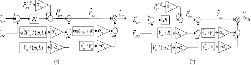
and the leg offsetvoltage (vx0), the balancing control strategy is shown as a block diagram in Fig. 2(a). Eerr is the energy difference between the upper and lower arms as in (21). Eerr∗ is the reference of energy difference and should be set as null to keep the balance of the arm energies
Eerr = Exp−ExN =1
2Ccell (vx cp
i)2− Ni=1(vxcNi)2 (21)
Perrvff in Fig. 2(a) can be derived as (22) by (20)
Perrvff = 1
2Vdcixs−2vdc
∗ i
x0 (22)
In the case of the square leg offset voltage injection, on the other hand, the square wave voltage can be injected to both the common mode and the leg offset voltage as shown in Fig. 2(b). In this case, vsn∗ can be defined by (23) and f
hstands for the frequency of the injected high-frequency voltage
vsn∗ =
−vsn 0≤t <2f1 h
vsn 1
2fh ≤t < 1 fh
Available online: https://edupediapublications.org/journals/index.php/IJR/ P a g e | 3061 Under the assumption that the arm resistance, R, is
dominant during each given quasisteady half period, 1
2fh ,vxo
∗
can be estimated as (24) from (5), (15), and (23)
Perrvff in Fig. 2(b) can also be derived from (22) using
(24) similarly with the case of sinusoidal wave.
B. Normal Frequency Mode
Since the output frequency is high enough in the normal frequency mode, the voltage fluctuation of the cell capacitor is tolerable. In this mode, the circulating current is controlled to have only dc component to minimize the conduction loss caused by the additional circulating current. As the operation frequency increases, meanwhile, the boundary of the common mode voltage decreases. Hence, the common mode voltage availability is less for balancing control.
Practical MMC systems may have a built-in unbalance due to slight asymmetries in cells, structural errors, and other Issues. Therefore, in normal frequency mode it should be performed just to eliminate the present small dc unbalances. The balancing can be achieved using the circulating current as 2vxs∗ i
x0 in (12). By adjusting the leg offset voltage for
circulating current to have fundamental frequency component, this dc unbalance can be suppressed.
Fig.2. Proposed control scheme for variable-speed drives. (a) Sinusoidal wave voltage injection method. (b) Square wave voltage injection method. 𝛼wis weighting factor for switchover, which is described in Section III-C.
C. Switchover Between Two Modes
As mentioned previously, as the high-frequency components of the common mode and leg offset voltage are only injected in low-operating frequency modes, the leg offset voltage reference changes with respect to the output frequency of MMC. A switchover tactic between the low- and high-frequency modes shown in Fig. 3 is devised by the weighting factor, 𝛼w. In addition, this factor is applied to the switchover of the balancing control scheme shown in Fig. 2. In addition, the tactic would have the hysteresis band to prevent chattering in the vicinity of the switchover frequency, fcut.
IV. OVERALL CONTROL SCHEME FOR ENTIRE
FREQUENCY OPERATION
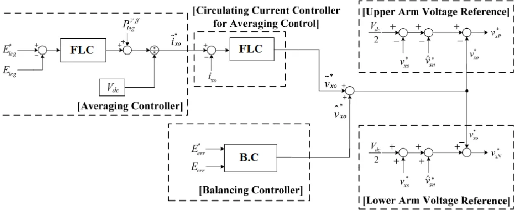
Fig. 4 shows the overall controller for the entire frequency operation from standstill to normal frequency mode. First, the averaging controller regulates the leg power, which is the difference between output leg power and dc-link input power is calculated as (25) adding (8) and (9)
Pxp + PxN ≈VdcIx0−2vdc∗ ix0−vsn∗ i
xs (25)
Available online: https://edupediapublications.org/journals/index.php/IJR/ P a g e | 3062
P
xp+ P
xN≈
V
dci
∗x0−
v
xs∗i
xs= 0
(26)
i
x0∗= v
xs∗i
xs/V
dc(27)
Fig. 3. Relationship between operating frequency and weighting factor.
Eleg is the energy of the leg and Eleg can be calculated as (28). Eleg∗ is the reference energy of the leg as (29), where Vc∗
is the reference value of cell capacitor voltage, Vdc/N
Eleg = Exp + ExN =1
2Ccell (vx
cp
i)2+ (vxcNi)2 N
i=1 N
i=1
(28)
E
leg∗=
12 Ccell
2N
4N
2V
c∗2
= NC
cellV
c∗2(29)
The feed-forwarding power term, Perrvff, can be derived
as
v
xs∗i
xs from (27). Therefore, the PI controller can simply beadopted as the circulating current controller for the averaging
Fig.4. Proposed overall control scheme for variable-speed drives
control. The details about the averaging controller are described in [10].
In the interim, the balancing controller can be picked between two schemes in Fig. 2 that are in particular, the sinusoidal and the square wave voltage injections. As displayed in Fig. 4, the balancing controller specifically influences the leg
Available online: https://edupediapublications.org/journals/index.php/IJR/ P a g e | 3063 At last, the upper and lower arm voltage references are
incorporated as (6) and (7), which are made out of
v
xs∗ from theyield of stage current controller,
v
x0∗ from the averaging andadjusting controller, and the infused normal mode voltage of vsn∗ .
V. FUZZY LOGIC CONTROLLER
In FLC, essential control activity is dictated by an arrangement of etymological principles. These guidelines are controlled by the framework. Since the numerical factors are changed over into semantic factors, scientific displaying of the framework isn't required in FC. The FLC includes three sections: fuzzification, interference engine and defuzzification.
The FC is characterized as i. seven fuzzy sets for each input and output. ii. Triangular membership functions for simplicity. iii. Fuzzification using continuous universe of discourse. iv. Implication using Mamdani‟s, „min‟ operator. v. Defuzzification using the height method.
Fig.5 Fuzzy logic controller
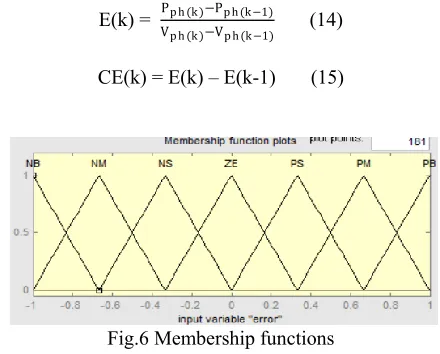
Fuzzification: Membership function esteems are doled out to the etymological factors, using seven fuzzy subsets: NB (Negative Big), NM (Negative Medium), NS (Negative Small), ZE (Zero), PS (Positive Small), PM (Positive Medium), and PB (Positive Big). The partition of fuzzy subsets and the shape of membership CE(k) E(k) function adapt the shape up to appropriate system. The value of input error and change in error are normalized by an input scaling factor.
Table I FUZZY RULES
Change
in error Error NB NM NS ZE PS PM PB
NB NB NB NB NB NM NS ZE
NM NB NB NB NM NS ZE PS
NS NB NB NM NS ZE PS PM
ZE NB NM NS ZE PS PM PB
PS NM NS ZE PS PM PB PB
PM NS ZE PS PM PB PB PB
PB ZE PS PM PB PB PB PB
In this system the input scaling factor has been designed such that input values are between -1 and +1. The triangular shape of the membership function of this arrangement presumes that for any particular E(k) input there is only one dominant fuzzy subset. The input error for the FLC is given as
E(k) = Pp h (k )−Pp h (k−1)
Vp h (k )−Vp h (k−1) (14)
CE(k) = E(k) – E(k-1) (15)
Fig.6 Membership functions
Inference Method: A few structure techniques, for example, Max– Min and Max-Dot have been proposed in the writing. In this paper Min strategy is utilized. The yield enrollment capacity of each lead is given by the base administrator and most extreme administrator. Table 1 indicates run base of the FLC.
Defuzzification: As a plant as a rule requires a non-fuzzy estimation of control, a defuzzification arrange is required. To process the yield of the FLC, "height" strategy is utilized and the FLC yield alters the control yield. Further, the yield of FLC controls the switch in the inverter. In UPQC, the dynamic power, responsive power, terminal voltage of the line and capacitor voltage are required to be kept up. Keeping in mind the end goal to control these parameters, they are detected and contrasted and the reference esteems. To accomplish this, the enrollment elements of FC are: blunder, change in mistake and yield.
The set of FC rules are derived from
u=-[αE + (1-α)*C]
Available online: https://edupediapublications.org/journals/index.php/IJR/ P a g e | 3064 VI. SIMULATION RESULTS
To check the sufficiency of the proposed control approach, an adaptable speed drive system based on 12-kV 24-MVA MMC has been implemented using the time-domain simulation program, MATLAB. The number of cells in each arm N, equals 20. Thus, the system with 120 cells was simulated. Each cell capacitor voltage is controlled as 600 V, and the cell is composed of the half-bridge inverter and the cell capacitance is 6000 μF. The nearest level modulation is applied to generate the arm voltage references and reduce the loss in switching action of MMC [15]. The cell voltage sorting algorithm is applied to the cell voltage balancing [14]. The parameters used in the simulations are listed in Table II.
TABLE II
CIRCUIT PARAMETERS OF THE SIMULATION
TABLE III
PMSM SPECIFICATION OF THE SIMULATION
Simulink modeling diagrams:
Available online: https://edupediapublications.org/journals/index.php/IJR/ P a g e | 3065
Available online: https://edupediapublications.org/journals/index.php/IJR/ P a g e | 3066 Fig.10 Overall control scheme
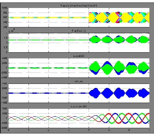
Fig 9. Simulation waveform when applying the conventional circulating current injection method with 6 r/min speed and step
load torque from 10% to 36% of the rated torque
Fig.11 Block diagram of controller strategy
Fig.12 Fuzzy controller
It is assumed that the 21-level MMC system drives a 20 MW 20-pole permanent magnet synchronous machine (PMSM) with adjustable mechanical load. The PMSM parameters are summarized in Table III.
From the simulation results concocted technique can be connected to high-control medium voltage customizable drive framework in view of MMC. From the dynamic correlation between circling current infusion with the internal current circle and the proposed leg balance voltage infusion strategy, it can be presumed that the proposed technique may be a satisfactory answer for high-control medium voltage drives in view of MMC under necessities of extensive torque aggravation and unfaltering state operation down to a couple of percent of rated frequency.
Available online: https://edupediapublications.org/journals/index.php/IJR/ P a g e | 3067 In the meantime, in Fig. 9, the simulation results with
the ordinary circulating current implantation system in light of the internal current overseeing circle is showed up. Each working condition are indistinct to those in Fig. 8 beside the degree of the movement stack torque. For sensible examination between the customary current imbuement and proposed leg offset voltage mixture procedures, the information transmission for the modifying controller of the torque two strategies is set as the same, and the repeat of the implanted section was similarly set as the same, 100 Hz. The degree of the movement stack torque associated at the standard current imbuement procedure is 36% of the evaluated torque, which isn't precisely the proposed strategy test in Fig. 8. As showed up in Fig. 9, the system in perspective of the general procedure winds up obviously wobbly and backs off in a moment toward the end. After the sudden propel stack torque is associated at 4 s, the cell capacitor voltage changes are greater than the instabilities while using the leg adjust voltage implantation system in Fig. 8.
VII. CONCLUSION
In this paper, a control strategy for variable-speed ac motor drives based on MMC has been presented. To overcome the difficulties of the power balance between cells and arms of MMC over wide operation speed ranges, a direct leg offset voltage injection method has been devised. Using the professional postured technique, the swell voltage of every cell of MMC has been kept inside reasonable limits under the sudden utilization of 40% of evaluated stack torque at the to a great degree low recurrence, 1 Hz, which is <2% of appraised recurrence. In view of the reproduction and exploratory outcomes, it can be noticed that the control execution of the upper and lower arm vitality swell by the proposed leg counterbalance voltage infusion technique is superior to that by the customary coursing current infusion strategy with the inward circle. What's more, the variable speed air conditioning engine drive has been demonstrated to work in light of the switchover strategy by testing the general speed including zero speed.
REFERENCES
[1] A. Lesnicar and R. Marquardt, “An innovative modular multilevel converter topology suitable for a wide power range,” in Proc. IEEEPower Tech Conf., Bologna, Italy, Jun. 2003.
[2] Hiller, D. Krug, R. Sommer, and S. Rohner, “A new highly modular medium voltage converter topology for industrial drive applications,” in Proc. 13th Eur. Conf. Power Electron. Appl., Sep. 2009. pp. 1–10.
[3] G. P. Adam, O. Anaya-Lara, G. M. Burt, D. Telford, B. W. Williams, and J. R. McDonald, “Modular multilevel inverter: Pulse width modulation and capacitor balancing technique,” IET Power Electron., vol. 3, no. 5, pp. 702–715, Sep. 2010.
[4] H. M. Pirouz, M. T. Bina, and K. Kanzi, “A new approach to the modulation and DC-link balancing strategy of modular multilevel AC/AC converters,” in Proc. Int. Conf. PEDS, 2005, vol. 2, pp. 1503–1507.
[5] A. Antonopoulos, K. Ilves, L. Angquist, and H.-P. Nee, “On interaction between internal converter dynamics and current control of high-performance high-power AC motor drives with modular multilevel converters,” in Proc. IEEE ECCE, Sep. 2010, pp. 4293–4298.
[6] M. Hagiwara, K. Nishimura, and H. Akagi, “A medium-voltage motor drive with a modular multilevel PWM inverter,” IEEE Trans. Power Electron., vol. 25, no. 7, pp. 1786–1799, Jul. 2010.
[7] M. Hagiwara, I. Hasegawa, and H. Akagi, “Start-up and low-speed operation of an electric motor driven by a modular multilevel cascade inverter,” IEEE Trans. Ind. Appl., vol. 49, no. 4, pp. 1556–1565, Jul./Aug. 2013.
[8] J. Kolb, F. Kammerer, and M. Braun, “Straight forward vector control of the modular multilevel converter for feeding three-phase machines over their complete frequency range,” in Proc. 37th Annu. Conf. IEEEInd. Electron. Soc. IECON, Nov. 2011, pp. 1596–1601.
[9] A. Antonopoulos, L. Angquist, S. Norrga, K. Ilves, and H.-P. Nee, “Modular multilevel converter AC motor drives with constant torque form zero to nominal speed,” in Proc. IEEE ECCE, Sep. 2012, pp. 739–746.
[10] J.-J. Jung, H.-J. Lee, and S.-K. Sul, “Control of the modular multilevel converter for variable-speed drives,” in Proc. IEEE Int. Conf. PEDES, Dec. 2012, pp. 1–6.
[11] L. Angquist, A. Antonopoulos, D. Siemaszko, K. Ilves, M. Vasiladiotis, and H.-P. Nee, “Inner control of modular multilevel converters-an approach using open-loop estimation of stored energy,” in Proc. IPEC, Jun. 2010, pp. 1579–1585. [12] T. Wang and Y. Zhu, “Analysis and comparison of multicarrier PWM schemes applied in H-bridge cascaded multi-level inverters,” in Proc.5th ICIEA, Jun. 2010, pp. 1379–1383. [13] S. Rohner, S. Bernet, M. Hiller, and R. Sommer, “Modulation, losses, and semiconductor requirements of modular multilevel converters,” IEEE Trans. Ind. Electron., vol. 57, no. 8, pp. 2633–2642, Aug. 2010.
[14] X. Shi, Z. Wang, L. M. Tolbert, and F. Wang, “A comparison of phase disposition and phase shift PWM strategies for modular multilevel converters,” in Proc. IEEE ECCE, Sep. 2013, pp. 4089–4096.
Available online: https://edupediapublications.org/journals/index.php/IJR/ P a g e | 3068 [16] A. J. Korn, M. Winkelnkemper, and P. Steimer, “Low
output frequency operation of the modular multi-level converter,” in Proc. IEEE ECCE, Sep. 2010, pp. 3993–3997.
G. Ajay Krishna Completed B. TECH in
Electrical & Electronics Engineering in 2015 from Sree Dattha College Of Engineering ,affiliated to Jawaharlal University, Hyderabad and Pursuing M.TECH form ANURAG Group of Institutions (Formerly known as CVSR College of Engineering(Autonomous)) Affiliated to JNTUH, Hyderabad, Telangana, India. Area of interest includes Power Electronics, electrical Machines and drives control.