Psc Based Maximum Power Point Tracking Of Pv Arrays Partial
Shading Detection With Incremental Conductance
K. Sai Kishore & N. Ram Chander
1PG.Scholar, B V Raju Institute of Technology (Autonomous), Narsapur, Hyderabad, Telangana, India 2 AssociateProfessor, B V Raju Institute of Technology (Autonomous), Narsapur, Hyderabad, Telangana, India.
ABSTRACT: -
A
n enhanced examination of maximum power point tracking (MPPT) amidst incremental conductance (IC) of sunlight hinged photovoltaic cluster under incomplete shaded condition is suggested here. Suggested framework is basic and savvy. Under PSC, P-V normal for PV exhibits will have different pinnacle focuses; just one is worldwide most extreme. This paper suggests an IC technique is employed; it is employed to track MPPT purpose of PV source. MPPT can limit framework cost and boost exhibit productivity. Regular MPPT techniques do not separate greatest power in this condition. This paper suggests novel two-arrange MPPT strategy is displayed to defeat this disadvantage. In primary stage, a technique is suggested to decide event of PSC, and in second stage, using a new algorithm that is hinged on ramp change of duty cycle and continuous sampling from P-V characteristic of array, global MPPT of array is reached. Open circle operation of suggested technique makes its execution shabby and straightforward. IC calculation was intended to supervise obligation cycle of Buck Boost converter and to guarantee MPPT work at its maximum proficiency. By utilizing replication comes about we can dissect suggested strategy.Keywords - DC/DC converter, maximum power point tracking (MPPT), Incremental conductance, Partial shading condition, Photovoltaic power generation entity.
1. INTRODUCTION
PV supervise age frameworks have one major issue that measure of electric power originated by PV detachment is continually changing amidst climate conditions, i.e., light. Therefore According to MPPT supervise scheme which employed tracking MPP at continuous mode which is hinged upon PV entity.
The reason for this paper is to study and look at three MPPT scenarios in PV replication framework utilizing IC strategy. Amidst expansion sought after of vitality it wanted to change to sustainable power sources and sunlight hinged photovoltaic is perfect efficient power vitality.
According to MPPT algorithm amidst successful PSC which also have following prosperities, they are 1) Tracking MPP quickly to get immense productivity, 2) Simple usage amidst a low computational load, 3) Requiring less and less expensive sensors (expelling current sensors of lift converter lessens cost significantly),
4) Imposing least unsettling influence to associated network.
This paper suggests, a novel MPPT calculation is exhibited which depends on entrance ramp change of obligation cycle and ceaseless examining from P-V normal for cluster. Basic and modest execution for open circle operation, immense and flexible speed, vigorous and ensured execution in all conditions, and forcing least unsettling influence to associated supervise framework are boons of suggested technique. Likewise, another calculation for identifying PSC event on PV exhibit is displayed that has execution prevalence over present techniques.
Majority of these scenarios comprise of two stages to accomplish GMPP. Suggested MPPT in [10] utilizes a controllable current transformer (CCT) arranged at terminal of each PV detachment, allowing good current in arrangement way of PV string. CCT yield current conceivably controlled utilizing a needy current source as per MPPT calculation. For fact that exactness of these scenarios is immense and they diminish impact of PS on exhibit control, their execution is costly.
In these techniques, GMPP were tested by distinctive purposes of exhibit P-V trademark. These scenarios are for most part effective, yet their examining number is high. Since GMPP can happen in an extensive variety of P-V trademark, beginning testing must cover whole bend. Strategy suggested has great execution, yet it is required to quantify voltage of every detachment. This technique proposes two scenarios: primary approach tests P-V bend and restricts pursuit region for short out current of detachments and most astounding nearby power.
2. OBJECTIVE
This paper suggests, a novel MPPT calculation is exhibited which depends on entrance ramp change of obligation cycle and constant –examining from P-V normal for cluster. Basically it is employed for open circle operation, immense and flexible speed, hearty and ensured execution in all conditions, and forcing least unsettling influence to associated supervise framework are boons of suggested strategy. Likewise, another calculation for distinguishing PSC event on PV cluster is exhibited that has execution prevalence over present techniques.
Generally, different prototypes are exhibited for sun hinged cells. Among these prototypes, single-diode display that is exhibited in Fig. 1 is employed as a part of this paper. For this prototype, connection between voltage (V) and current (I) of PV detachment is communicated as follows:
𝐼 = 𝐼𝑃𝑣− 𝐼𝑜 𝑒𝑥𝑝 𝑉+𝑅𝑠𝐼
𝐴𝑉𝑇 − 1 − 𝑉+𝑅𝑠𝐼
𝑅𝑠 (1) According to equivalent photocurrent of detachment, is invert immersion current of equal diode, A is perfect factor, and is thermal voltage of detachment. Likewise, and are proportional arrangement and shunt protections of detachment. I-V characteristic of an array amidst parallel strings, each comprising of arrangement detachments, in UIC is then as takes after.
𝐼 = 𝑁𝑝𝐼𝑝𝑣− 𝑁𝑝𝐼0 𝑒𝑥𝑝 𝑉+𝑁 𝑠
𝑁 𝑝𝑅𝑠𝐼
𝐴𝑁𝑠𝑉𝑡 − 1 + 𝑉+𝑁 𝑠
𝑁 𝑝𝑅𝑠𝐼 𝑁 𝑠 𝑁 𝑝𝑅𝑠
(2)
Fig.1. Single-diode electrical prototype of PV detachment.
According to paper there are few symbol representing which are employed below there are 𝑉𝑜𝑐 _𝑚𝑜𝑑is delineated as open circuit voltage of PV detachment,𝑉𝑜𝑐 _𝑠𝑡𝑟is delineated as open circuit voltage of PV string, 𝑉𝑜𝑐 _𝑎𝑟𝑟is delineated as open circuit voltage of PV array, Vmpp is delineated as voltage MPP , 𝑉𝑚𝑝𝑝 _𝑠𝑡𝑟 is delineated as voltage string at its MPP at UIC and 𝑉𝑚𝑝𝑝 _𝑎𝑟𝑟 is delineated as array voltage at MPP under UIC
(a)
(b)
(c)
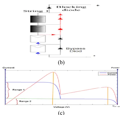
Fig. 2. (a) P-V and I-V qualities of an average PV detachment. (b) Structure of an example shaded string.
(c) P-V and I-V attributes of shaded string The detachment current is greatest at and is known as short out current. For voltages above there will be negative current, yet a blocking diode will constrain it to zero. According to V-I and P-V characteristics of solar detachment which is under UIC is delineated below. Therefore in cases of UIC MPP of detachment amidst array which are achieved at 𝑉𝑚𝑝𝑝 _𝑚𝑜𝑑 =∝ 𝑉𝑜𝑐 _𝑚𝑜𝑑 and 𝑉𝑚𝑝𝑝 _𝑚𝑜𝑑 =∝ 𝑉𝑜𝑐 _𝑎𝑟𝑟 = 𝑁𝑠𝑉𝑚𝑝𝑝 _𝑚𝑜𝑑 respectively and ∝ is delineated as coefficient which is confide on prototype parameter of solar detachment.
b) Partially Shaded Condition
For simplification, it is at first assumed that exhibit under PSC is subjected to two diverse irradiance levels. Detachments that get immense irradiance level are called insolated detachments and those which get bring down irradiance level are named shaded detachments.
The insolated detachments of string drive string current. Hence, segment of string current that is more prominent than created current of shaded detachments goes through parallel protection of shaded detachments and produces negative voltage crosswise over them. In this manner, shaded detachments devour supervise as averse to producing it. In this condition, general effectiveness drops, as shaded detachments might be harmed because of problem areas.
c) Critical Observations under PSC
of one shaded detachment is about. string voltage in this nearby MPP is bound as takes after
𝑁𝑆𝑉𝑚𝑝𝑝 −𝑚𝑜𝑑 < 𝑉𝑚𝑝𝑝 −2< 𝑛𝑠𝑉𝑚𝑝𝑝 −𝑚𝑜𝑑 + 𝑛𝑖𝑛𝑉𝑜𝑐 −𝑚𝑜𝑑 (3)
At point when irradiance proportion decreases, evokes near to lower bound of (3), and as it expands, pushes toward as far as possible.
4. OPEN LOOP supervise OF BOOST CONVERTER IN PV entity
In Fig.3, a two-stage matrix associated close planetary entity is exhibited. in primary stage, DC/DC help converter assumes fundamental part in engrossing force from PV cluster by controlling its voltage. in second stage, an inverter controls yield voltage of DC/DC converter and produces AC voltage to associate nearby planetary group to matrix. On account of DC connect capacitor between lift converter and inverter, there is small coupling between two phases and stages conceivably considered independently [25].
Fig.3. Overview of two-stage grid connected PV entity structure.
For most part, there are two supervise approaches for direction of PV exhibit utilizing support converter; i.e. close circle and open circle controls. Reference [23] demonstrates that in a PV cluster associated amidst lift converter, most pessimistic scenario from solidness and dynamic reaction perspectives happens when exhibit works in consistent current area and low irradiance level, where dynamic protection of cluster has its biggest negative esteem.
In contrast, in open loop control, which is a common method for boost converters control, there is no feedback, and appropriate input voltage is generated considering relation between input voltage and output voltage of converter as in (4).
𝑣𝑖𝑛 = 𝑣𝑝𝑣= 1 − 𝐷 𝑣0 (4)
In this method, it is not necessary to measure boost converter inductor current and an expensive current sensor is saved. However, entity response may have some steady state error and more transients than close loop method. One of important parameters in MPPT of PV entity is sampling time.
Fig.4. Response of switching and averaged state space prototypes of boost converter in PV entity to step and
ramp commands
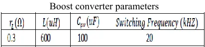
For further analysis, response of PV array connected to a boost converter amidst open loop supervise is studied through simulation in Matlab/Simulink environment. Converter parameters are delineated in Table I and simulated PV array. Output voltage of boost converter is also considered constant at 250V.
Table I
Boost converter parameters
Both switching and averaged state space prototypes of entity are simulated and their responses to step and ramp command signals by open loop supervise are delineated in Fig. 4. Following conclusions are made from entity response:
1) Responses of accurate switching prototype and averaged state space prototype are almost identical.
2) Entity response to step and ramp command signals contain some steady state error. This error can deteriorate MPPT methods that are hinged on sampling from specific points of array’s P-V characteristic [13].
3) Oscillation, overshoot and settling time of entity to step commands is high, especially when operating point in constant current region of PV array, which impose higher switching stress and losses. In contrast, ramp response has negligible transient.
4) Settling time of entity step response is about 15ms. Thus, for MPPT application, sampling time must be more than 15ms. It is noteworthy that is considered high, while in practice, for better efficiency, it is lower and results in higher settling time.
5. PARTIAL SHADING CONDITION DETECTION
According to following section, algorithm of PSC detection which is delineated which is confide upon three criteria according to final performance of algorithm which is evaluated in different PS pattern.
The primary suggested prototype depends on another list that is characterized as takes after:
𝑃𝑆𝐼 = ∆𝑃
∆𝑉.𝑃 𝑉𝑚𝑝𝑝 −𝑎𝑟𝑟 = 𝜕𝑃 𝜕𝑉
𝑉.𝐼 𝑉𝑚𝑝𝑝 −𝑎𝑟𝑟 = 𝜕 (𝑉𝐼 )
𝜕𝑉
𝑉.𝐼 𝑉𝑚𝑝𝑝 −𝑎𝑟𝑟 =
1𝑉𝑚𝑝𝑝−𝑎𝑟𝑟+𝜕𝐼𝐼.𝜕𝑉𝑉𝑚𝑝𝑝−𝑎𝑟𝑟 (5)
According to criterion which is derivative of PV array power which is respect to array voltage at 𝑉𝑚𝑝𝑝 _𝑎𝑟𝑟 = 𝑁𝑠𝑉𝑚𝑝𝑝 _𝑚𝑜𝑑 = 𝑉𝑚𝑝𝑝 _𝑠𝑡𝑟 which is similar employed by IC method for MPPT. Therefore at UIC, PSI is to be zero .according to PSC ,the local MPP voltage will be change from 𝑉𝑚𝑝𝑝 _𝑎𝑟𝑟 and there are also defined that PSI will not be zero and it will confide upon shading pattern. Therefore according to cases II, whenever PV string will under PSC voltage will across shaded detachment 𝑉𝑚𝑝𝑝 _𝑠𝑎𝑑𝑒𝑑 at 𝑉𝑚𝑝𝑝 _𝑠𝑡𝑟 = 𝑁𝑠𝑉𝑚𝑝𝑝 _𝑚𝑜𝑑 which is follows by
𝑁𝑠𝑉𝑚𝑝𝑝 −𝑚𝑜𝑑−𝑛𝑖𝑛𝑉𝑜𝑐 −𝑚𝑜𝑑
𝑁𝑠−𝑛𝑖𝑛 < 𝑉𝑚𝑜𝑑 −𝑠𝑎𝑑𝑒𝑑 < 𝑉𝑚𝑝𝑝 −𝑚𝑜𝑑 (6) From (6) two cases may arise for
𝜕𝐼
𝐼𝜕𝑉 𝑉𝑚𝑝𝑝 −𝑎𝑟𝑟: 1) 𝑁𝑠𝑉𝑚𝑝𝑝 −𝑚𝑜𝑑 > 𝑛𝑖𝑛𝑉𝑜𝑐 −𝑚𝑜𝑑
In this condition, is certain and total estimation of is not as much as its incentive in UIC, neighborhood MPP of string is 𝑣 > 𝑉𝑚𝑝𝑝 _𝑎𝑟𝑟 where PSI will be positive 2) 𝑁𝑆𝑉𝑚𝑝𝑝 −𝑚𝑜𝑑 < 𝑛𝑖𝑛𝑉𝑜𝑐 −𝑚𝑜𝑑
For this situation shaded detachments are skirted amidst sidestep diodes. Insolated detachments work in steady voltage locale. Hence, is substantially greater than its incentive in UIC; PSI is negative and neighborhood MPP of string.
Fig.5. I-V and P-V characteristics of PV string in different PSCs.
Therefore according to verification effectiveness of PSI index in PSC detection will have behavior of sample string which is denoted by array which is analysis by different PS pattern.
According to cases II and in (3) which is delineated easily that shading string whenever 𝐾 = 𝑛𝑠
𝑛𝑖𝑛 will be too immense and second local MPP will be 𝑉𝑚𝑝𝑝 _2 will be close to 𝑉𝑚𝑝𝑝 _𝑠𝑡𝑟. Therefore according to PSI index which may be zero and detection will be fails. Therefore according to 𝐼𝑅 = 𝐻𝑆 𝐿𝑆 must be
low. according to suggested algorithm which may be mistaken by detection of PSC which is mention below therefore main aim is that GMPPTG will not be lost according to fact is that under PSC which is considered amidst two local MPP, therefore first one will be 𝑉𝑚𝑝𝑝 _1< 𝑉𝑚𝑝𝑝 _𝑠𝑡𝑟 and 𝑃𝑚𝑝𝑝 _1≈ 𝑛𝑛𝑖𝑉𝑚𝑝𝑝 _𝑚𝑜𝑑𝐼𝑚𝑝𝑝 _1 and another one will be 𝑉𝑚𝑝𝑝 _2> 𝑉𝑚𝑝𝑝 _𝑠𝑡𝑟 amidst following power relation:
𝑃𝑚𝑝𝑝 −2= 𝑉𝑚𝑝𝑝 −2𝐼𝑚𝑝𝑝 −2≈ 𝑉𝑚𝑝𝑝 −2 1
𝐼𝑅 . 𝐼𝑚𝑝𝑝 −1> 𝐾 + 1 𝑛𝑖𝑛𝑉𝑚𝑝𝑝 −𝑚𝑜𝑑
1
𝐼𝑅 . 𝐼𝑚𝑝𝑝 −1= 𝐾 +
11𝐼𝑅𝑃𝑚𝑝𝑝−1 (7) Clearly when IR is too low or K is too immense (a similar circumstance that PSI record might be close to zero, e.g. PSC1 in Fig. 5). Hence, if PSI record botches in discovery of this PSC, regular P&O calculation employed as a part of UICs tracks second MPP which is GMPPT.
b) Updating and Final PS Detection Criteria
Up to this point, it was gathered that is accessible for PSI assessment. There are subject to sort of detachments and temperature as in (8); and furthermore, there is some distinction between temperatures of shaded and insolated detachments.
𝑉𝑚𝑝𝑝 −𝑎𝑟𝑟 = 𝑉𝑚𝑝𝑝 −𝑎𝑟𝑟 −𝑆𝐶∗ 1 − 𝜌𝑎𝑟𝑟 𝑇 − 25 = 𝑉𝑚𝑝𝑝 −𝑚𝑜𝑑 −𝑆𝑐∗∗ 1 − 𝜌𝑚𝑜𝑑 −𝑡 𝑇𝑡− 25 𝑁𝑠
𝑖=1 (8)
Where 𝑉𝑚𝑝𝑝 _𝑎𝑟𝑟 _𝑠𝑐 and 𝑉𝑚𝑝𝑝 _𝑚𝑜𝑑 _𝑠𝑐 are 𝑉𝑚𝑝𝑝 _𝑎𝑟𝑟 and 𝑉𝑚𝑝𝑝 _𝑚𝑜𝑑 which is in standard condition (𝑠 = 1𝐾𝑊 𝑚2, 𝑇 = 25𝐶) respectively and T will be denoted as temperature and 𝜌𝑎𝑟𝑟 and 𝜌𝑚𝑜𝑑 which are temperature confide coefficient of 𝑉𝑚𝑝𝑝 _𝑎𝑟𝑟 and𝑉𝑚𝑝𝑝 _𝑚𝑜𝑑. In this circumstance, it isn't certain whether specimen detachment is insulated or shaded. Appropriately, three cases might be fronted as takes after: 1).The entire exhibit is in UIC, and similarly, temperature of all detachments is same as specimen detachment temperature. Similarly, there is no mistake in refreshing for this situation, and UIC conceivably recognized utilizing PSI file.
2).The exhibit is in PSC and example detachment is insulated. In this manner, figured estimation of PSI and contrast between genuine nearby MPP voltage and refreshed will be more noteworthy than its genuine esteem. Subsequently, PS recognition winds up plainly less demanding.
3).The cluster is in PSC and example detachment is shaded. At long last, criteria for PS location will be as per following.
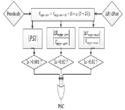
𝑃𝑆𝐼 > 0.001 ∆𝑉𝑚𝑝𝑝 −𝑒𝑟𝑟𝑜𝑟
𝑉𝑚𝑝𝑝 −𝑒𝑟𝑟𝑜𝑟 > 0.02 (9) ∆𝑉𝑚𝑝𝑝 −𝑒𝑟𝑟𝑜𝑟
According to specified thresholds in (9) are resolved by reproductions of numerous PS situations on different structures of PV cluster. In light of these criteria, exhibit is in PSC if no less than one of these conditions is met. In Fig. 6, stream outline of suggested calculation for PS discovery is exhibited
Fig.6. Flow chart of suggested algorithms for PS detection.
According to suggested algorithm which were studied in case of string of series detachments. In (10), it is delineated that PSI of cluster is weighted normal PSI of individual strings, and in this manner, utilizing PSI and two other criteria in (9) gets job done for PS discovery in any exhibit.
𝑃𝑆𝐼 = ∆𝑃
∆𝑉.𝑃|𝑉𝑎𝑝𝑝 −𝑎𝑟𝑟𝑎𝑦 = ∆𝑝𝑖
∆𝑉. 𝑃𝑖 𝑉𝑎𝑝𝑝 −𝑎𝑟𝑟𝑎𝑦 = 𝑃𝑆𝐼𝑖𝑃𝑖𝑃𝑖 (10)
Where 𝑃𝑖 and ∆𝑃𝑖 are denoted as power of string i amidst different respectively
Effectiveness of suggested algorithm for PSC detection
In following cases, a sample array will be simulated amidst different PSC which is verified by effectiveness of suggested PS detection algorithm
TABLE II
Electrical data of detachment nd195r1s in standard test condition
In this reproduction, detachments are under three distinct illuminations amidst accompanying related temperature. Arrangement and shunt protections of detachments are likewise considered in replications.
Fig.7. simulated array configuration (indicates sample detachment).
Results of five different PSC simulations are delineated in Table III.
Table III
Results of PSC detection in sample PSCS
Their method is hinged on observing a big power change, and is sensitive to relevant threshold: a smaller threshold may cause wrong detection of PSC, and a bigger one may result in missing it. In contrast, suggested method this paper suggests is activated in two ways: 1) periodically, 2) after observing a noticeable power change.
6. PROPOSED ALGORITHM FOR MPPT UNDER PSC
MPPT is a period fluctuating advancement issue, in which target work assessment is done physically; i.e. by applying particular voltages to cluster, its yield supervise is measured in wake of settling its voltage, though in numerical streamlining issues, work assessment is done numerically and forces figuring load on processor. Under PSC, GMPP is in accompanying voltage district that must be GMPPT:
𝑉𝑚𝑝𝑝 −𝑚𝑜𝑑 < 𝑉 < 𝑉𝑜𝑐 −𝑎𝑟𝑟 (11) As per above discourse, two critical certainties move utilizing slope voltage as charge flag of converter to look through voltage locale of (11) for GMPPT: 1). As averse to reaction of lift converter to step summons, settling time and transient of lift converter to incline charge is almost zero ( Fig. 4).
In two unique circumstances that may happen for PV cluster, suggested calculation for GMPPT works as takes after:
a) While exhibit is under UIC and works at a PS happens and working point changes.The suggested PSC identification calculation is started by this power change, and decides if cluster is still at UIC or has experienced PSC. Something else, suggested MPPT calculation is enacted. for suggested MPPT strategy, greatest exhibit supervise amid MPPT process and its comparing voltage are introduced.
b) exhibit is under PSC and shading design changes. In different condition which is confide upon suggested contents which will bring array voltage to 𝑉𝑚𝑝𝑝 _𝑎𝑟𝑟.according to PS detection criteria which is verified to determine array at UIC or under PSC .if there is no PS is detected then P&O algorithm will known.MPPT will be process will be started by applying positive ramp voltage amidst command to converter.and rest of process will be same which is explained in (a)
Assume an example working purpose of cluster as . It is realized that when cluster voltage expands, its present abatements. Hence, exhibit current (Iarr ) for is 𝑉 > 𝑉𝑆 Consequently,
𝑃𝑎𝑟𝑟 𝑉 > 𝑉𝑆 = 𝑉𝐼𝑎𝑟𝑟 < 𝑉𝐼𝑠 (12) In addition, because maximum voltage of array is
𝑃𝑎𝑟𝑟 𝑉 > 𝑉𝑆 < 𝑉𝑜𝑐 −𝑎𝑟𝑟𝐼𝑠 (13)
7. INCREMENTAL CONDUCTANCE MPPT
In IC technique cluster terminal voltage is constantly balanced by MPP voltage it depends on incremental and momentary conductance of PV detachment.
Fig-8: Basic thought of IC strategy on a P-V Curve of sun powered detachment
According to Fig-8 which demonstrates that incline of P-V cluster supervise bend is zero at MPP, expanding on left of MPP and diminishing on Right hand side of MPP. fundamental conditions of this strategy are as per following.
𝑑𝑙
𝑑𝑣= −
1
𝑣 𝐴𝑡 𝑀𝑃𝑃 𝑑𝑙
𝑑𝑣> − 1
𝑣 𝐿𝑒𝑓𝑡 𝑜𝑓 𝑀𝑃𝑃 𝑑𝑙
𝑑𝑣< − 1
𝑣 𝑟𝑖𝑔𝑡 𝑜𝑓 𝑀𝑃𝑃 (14)
Where, I and V are P-V exhibit yield current and voltage individually. left hand side of conditions speaks to IC of P-V detachment and correct hand side speaks to quick conductance. At point when proportion of progress in yield conductance is equivalent to negative yield conductance, sun hinged exhibit will work at maximum power point.
8. INCRIMENTAL CONDUCTANCE MPPT ALGORITHM
This strategy misuses suspicion of proportion of progress in yield conductance is equivalent to negative yield Conductance Instantaneous conductance. We have,
𝑃 = 𝑉𝐼 (15) Applying chain rule for derivative of
𝜕𝑃
𝜕𝑉= 𝜕 𝑉𝐼 𝜕𝑉 𝜕𝑃
𝜕𝑉= 0 (16)
The above equation could be written in terms of array voltage V and array current I as
∂I/∂V = - I/V (17)
The MPPT regulates PWM supervise signal of dc – to – dc boost converter until condition: (∂I/∂V) + (I/V) = 0 is satisfied.
In this strategy, pinnacle energy of detachment lies at over 98% of its IC. Flow graph of IC MPPT is delineated as follows.
Fig.9. Flowchart for IC MPPT of switched PV approach.
9. SIMULATION RESULTS
In this section, performance of suggested method for GMPPT in PSC is evaluated in various aspects using simulations and experiments.
Simulation Results
Fig.9. P-V characteristics of array in UIC and two different PSCs.
Simulation results are delineated in Error! Reference source not found. (a-d), and efficiency of suggested MPPT algorithm is compared amidst PSO-based method and suggested method.
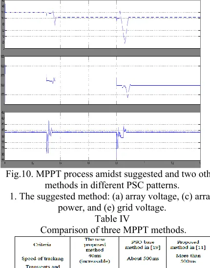
Fig.10. MPPT process amidst suggested and two other methods in different PSC patterns.
1. The suggested method: (a) array voltage, (c) array power, and (e) grid voltage.
Table IV
Comparison of three MPPT methods.
Since inspecting from of cluster P-V trademark in these scenarios are finished amidst particular interims which rely upon prototype of detachments, non-indistinguishable detachments in exhibit influence their Efficiency.
10. CONCLUSION
As indicated by paper we are executing a halfway shading condition recognition calculation. in primary stage, a strategy is suggested to decide event of PSC, and in second stage, utilizing another calculation
that depends entrance ramp change of obligation cycle and ceaseless inspecting from P-V normal for cluster, worldwide maximum power purpose of exhibit is come to. There are putting a novel straightforward and quick calculation which is indicated as addition state of MPPT under PSC that works as immediate supervise strategy and needs no input supervise of current and voltage. Reproduction comes about approve execution of suggested strategy in speed and precision. correlation demonstrates a promising execution for suggested reconfigurable PV exhibit contrasted amidst customary PV cluster amidst focal and strings inverters approaches.
11. REFERENCES
[1] T. Esram and P. L. Chapman, "Correlation of Photovoltaic Array Maximum Power Point Tracking Techniques," Energy Conversion, IEEE Transactions on, vol. 22, pp. 439-449, 2007
[2] Y.- J. Wang and P.- C. Hsu, "An examination on halfway shading of PV modules with various association designs of PV cells," Energy, vol. 36, pp. 3069-3078, 2011.
[3] D. Kun, B. XinGao, L. HaiHao, and P. Tao, "A MATLAB-Simulink-Based PV Module Model and Its Application Under Conditions of Nonuniform Irradiance," Energy Conversion, IEEE Transactions on, vol. 27, pp. 864-872, 2012.
[4] J. Youthful Hyok, J. Doo-Yong, K. Jun-Gu, K. Jae-Hyung, L. Tae-Won, and W. Chung-Yuen, "A Real Maximum Power Point Tracking Method for Mismatching Compensation in PV Array Under Partially Shaded Conditions," Power Electronics, IEEE Transactions on, vol. 26, pp. 1001-1009, 2011.
[5] E. Koutroulis and F. Blaabjerg, "A New Technique for Tracking the Global Maximum Power Point of PV Arrays Operating Under Partial-Shading Conditions," Photovoltaics, IEEE Journal of, vol. 2, pp. 184-190, 2012.
[6] N. Tat Luat and L. Kay-Soon, "A Global Maximum Power Point Tracking Scheme Employing DIRECT Search Algorithm for Photovoltaic Systems," Industrial Electronics, IEEE Transactions on, vol. 57, pp. 3456-3467, 2010.
[7] Syafaruddin, E. Karatepe, and T. Hiyama, "Manufactured neural system polar facilitated fluffy controller based greatest power point following control under mostly shaded conditions," Renewable Power Generation, IET, vol. 3, pp. 239-253, 2009.
[8] I. Abdalla, J. Corda, and L. Zhang, "Multilevel DC-Link Inverter and Control Algorithm to Overcome the PV Partial Shading," Power Electronics, IEEE Transactions on, vol. 28, pp. 14-18, 2013.
Shaded PV Source Using Current Compensation Concept," Power Electronics, IEEE Transactions on, vol. 29, pp. 4684-4692, 2014.
[10] C. Woei-Luen and T. Chung-Ting, "Ideal Balancing Control for Tracking Theoretical Global MPP of Series PV Modules Subject to Partial Shading," Industrial Electronics, IEEE Transactions on, vol. 62, pp. 4837-4848, 2015.
11] H. Patel and V. Agarwal, "Greatest Power Point Tracking Scheme for PV Systems Operating Under Partially Shaded Conditions," Industrial Electronics, IEEE Transactions on, vol. 55, pp. 1689-1698, 2008. [12] Y. Wang, Y. Li, and X. Ruan, "High Accuracy and Fast Speed MPPT Methods for PV String Under Partially Shaded Conditions," Industrial Electronics, IEEE Transactions on, vol. PP, pp. 1-1, 2015.
[13] A. Kouchaki, H. Iman-Eini, and B. Asaei, "another greatest power point following procedure for PV exhibits under uniform and non-uniform insolation conditions," Solar Energy, vol. 91, pp. 221-232, 2013.