MAC Protocol Based Power Control For WiFi Networks
Mr.V.Mutyalanaidu; Mr.V.Balaji; Mr.T.Ravibabu; Ms.Rupalin Nanda
(1).
VOLLURU MUTYALA NAIDU
pursuing M.E communication systems from Sanketika Vidya
Parishad Engineering College. Affiliated to Andhra University, Visakhapatnam.
(1).
VALLI BALAJI,
M.Techis currently working as a Assistant professor in Department of Electronics and
Communication Engineering in Sanketika Vidya Parishad Engineering College. Affiliated to Andhra
University, Visakhapatnam, Andhra Pradesh.
(2).
T.RAVI BABU,
M.Techis currently working as a Assistant professor in Department of Electronics and
Communication Engineering in Sanketika Vidya Parishad Engineering College. Affiliated to Andhra
University, Visakhapatnam, Andhra Pradesh.
(3).
RUPALIN NANDA,
M.Techis currently working as a Assistant professor in Department of Electronics
and Communication Engineering in Sanketika Vidya Parishad Engineering College. Affiliated to Andhra
University, Visakhapatnam, Andhra Pradesh.
Abstract:
Signal processing has illustrated in-band full-duplex ability at Wi-Fi ranges. Furthermore to synchronous two-path trade between two hubs, full-duplex get to focuses
can potentially support concurrent uplink and downlink streams. Be that as it may, the nuclear three-hub topology, which permits concurrent uplink and downlink, prompts
between customer obstructions. In this proposal an random access medium get to control convention utilizing dispersed power control to oversee between customer obstruction in remote systems with
recreations and software defined radio-based tests to assess the execution of the proposed MAC protocol, which is appeared to accomplish a huge change over its half-duplex partner as far as throughput execution.
Keywords:
MAC protocol, WiFi Networks, Half Duplex, Full Duplex, 802.11 IEEE Standard
1. Introduction:
IEEE 802.11 [1] protocol is the most widely used wirelessconnection standard in IP-based networks, and its advantagesover other wireless connection protocols, such as low cost,easy deployment and high bandwidth, will make it an importantcomponent in next generation networks. However, theradio range in IEEE 802.11 is limited, and mobile nodes needto change access points (APs) frequently during the movement.Therefore, changing APs smoothly is the key issue in IEEE802.11 networks.There are two phases in a handoff process: the MAC layerhandoff and the network layer handoff. When the mobile nodefinds quality of signal, which can be measured by the receivedsignal strength indication (RSSI) or a signal to noise ratio(SNR) below the predefined level in the MAC layer, the mobilenode initiates the handoff process to find and re-associate withthe AP that has the best quality of signal in the mobile node‟sneighbourhood. After that, the new data routing path betweenthe mobile node and its correspondent nodes should be re-establishedto maintain communication in the network layer.A
comprehensive survey of existing handoff
managementsolutions is given in [2]. IEEE 802.11b/g [1] protocol outlinesthe basic steps of the handoff process. Unfortunately, theoriginal handoff latency is of several hundred milliseconds [3],while the requirement for real-time applications for MAClayer handoff latency is less than 50ms. Therefore, muchresearch has proposed ways to reduce the handoff latency inrecent years.
Fig 1. Uplink (C1→AP) and downlink (AP→C4) network with full-duplexAP and half-duplex clients. However, these schemes do not work well inmultichannel wireless networks, since the mobile node haveto switch and scan multichannels. In IEEE 802.11b/g, thereare 14 channels, and channel 1 - 11 are available for usein North America [1]. Because the average time to switchchannels is 5ms [4], the total switching time for 11 channelsis more than 50ms, and it is hard to scan all channels withonly one mobile node. Thus, reducing the number of scanningchannels is an efficient way of minimizing handoff latency in MAC layer.
2. Related work:
A. Full-duplex Carrier Sensing
In the analysis of conventional HD-WiFi networks [2], noiseis often neglected. For simplicity and comparison fairness, wealso omit the noise in this letter. Thus, a silent user has aperfect sensing. We only need to analyze the imperfect sensingfor a transmitting user.Furthermore, the probability for the case with more thantwo collided users is negligible compared to the probabilitythat only two users collide, and even when the case happens,the sensing performance is also better than the case with twocollided users due to the accumulated collision signal. Thuswe assume perfect sensing for the case that three or moreusers collide, and the sensing errors only exist in the followingtwo cases: (1) H0: the
transmitting user singly occupies thechannel; (2) H1:
the transmitting user has a collision with another user.
Then the received signal for sensing at
wherestdenotes the transmitting user‟s signal and sc is thecollided user‟s signal, both of which have the same
power, hcrepresents the collision channel, and hr
denotes the equivalentRSI channel indicating the SIS degree, which depends on the adopted SIS techniques and network environment.
B. Full-duplex WiFi CSMA/CD Protocol
To resolve the problem of long collision duration, in theproposed FD-WiFi CSMA/CD protocol, a user keeps carriersensing continuously by using the FD technology. Similar tothe conventional HD-WiFi, an exponential backoff scheme isadopted in our protocol. At each packet transmission attempt, auser randomly sets its backoff timer in the range
[0,CWW−1],where CWW = 2WCWmin is called the
contention window,in which CWmin is the minimum
contention window, and Wdenotes the backoff stage.
At the first transmission attempt, Wis set to be zero,
and each unsuccessful transmission leads toW = W+1,
up to the maximum backoff stageWmax, in whichthe
maximum contention window CWmax=
2WmaxCWmin.The user‟s backoff timer is
decremented in every slot as longas the channel is sensed idle, “frozen” when busy channel isdetected, and “reactivated” when the channel is sensed idleagain for more than a distributed interference space (DIFS).Furthermore, the contending user accesses the channel andbegins transmitting when
backoff timer reaches zero. Duringthe data
transmission, if a collision is detected, the user stopstransmission and moves to the backoff procedure immediately.This transmission suspension process of FD-WiFi CSMA/CDprotocol mitigates the problem of long collision duration.
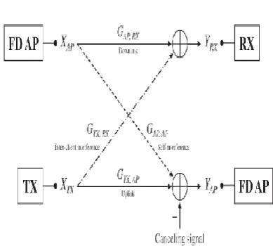
Fig 2. Wireless network model with a single full-duplex AP (separate transmittingand receiving components), one transmitter, and one receiver. 3. Proposed System:
A. Description of PoCMAC
We have proposed the RSSB contention scheme for receiverselection and the transmit power adjustment scheme to computethe optimal transmit powers of the AP and TX. In this section,we describe newly designed frame structures and detailed proceduresof the TX, RX, and AP for performing both schemes inPoCMAC.
Frame Structures:
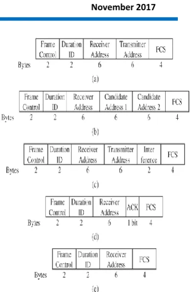
PoCMAC uses five types of controlframes and two types of DATA frame headers, as shown in Figs. 3 and 4. The five control frames are RTS, CTS-Uplink(CTS-U), CTS-Downlink (CTS-D), ACK-Downlink (ACK-D),and ACK-Uplink (ACK-U), and the two types of DATA frameheaders are the header of the AP (HA) and the header of theclient (HC).
Among these control frames and DATA
frameheaders, RTS, ACK-D, and HC have the same structures asRTS, ACK, and the DATA frame headers of the IEEE 802.11standard, respectively. The frame structures of CTS-U, CTS-D,ACK-U, and HA are newly designed in this study.The CTS-U frame is transmitted by the AP after it receivesan RTS frame from a client. This frame gives permissionto perform the uplink DATA transmission to the client.In addition, using the CTS-U frame, the AP informs thecandidate clients that it wants to transmit the DATA frame.The number of RX candidates that
can be listed in theCTS-U frame is set to M. The AP
frames in its transmissionqueue belong.1 The AP designates multiple candidates forthe RX to exploit the diversity of receivers. If only a singleclient were allowed to be listed as an RX candidate and ithappened to be close to the TX, it would not be possible tosuccessfully receive the DATA frame from the AP owingto strong interference from the TX. • The CTS-D frame is transmitted by the candidate clientthat wins the RSSB contention after the AP broadcastsa CTS-U frame. The CTS-D frame sent by a candidateclient informs the AP and the other RX candidates thatit has been selected as the RX that is to receive a DATAframe from the AP. Note that if a client overhears theCTS-U frame, it knows which client has been nominatedas the RX. This frame includes the address of the winningcandidate and the inter-client interference information,which is the received power of the RTS frame transmitted from the TX. If the RX cannot overhear the RTS framefrom the TX and cannot measure the signal strength fromthe TX, the interference field is filled with zeroes.
• The ACK-U frame is transmitted by the AP after completingthe uplink DATA reception from the TX. If the APsuccessfully receives the uplink DATA frame, it transmitsthe ACK-U frame with the ACK field set to “1”; otherwise,it transmits the ACK-U frame with the ACK field set to“0.” The AP always transmits the ACK-U frame regardlessof the success status of the uplink DATA frame. This isdone to inform all the clients that the transmission periodhas ended. The TX can confirm the success of its ownuplink DATA transmission via the ACK field in the ACKUframe transmitted from the AP, and the other clients candetect the completion of the transmission period via theACK-U frame transmitted from the AP.
Fig. 3. Control frame structures. (a) RTS. (b) CTS-Uplink (CTS-U). (c) CTSDownlink(CTS-D). (d) ACK-Uplink U). (e) ACK-Downlink (ACK-D).
Fig. 4.Header of DATA frame for AP and client. (a) Header of AP (HA).(b) Header of client (HC). B. Proposed PoCMAC:
Using the control frames and headers,the AP collects the inter-client interference informationfrom the RX, calculates the transmit powers for itself and theTX based on the collected information, and then informs theTX of the transmit power for the uplink DATA transmission example of the operation of the TX, RX, andAP. During the first transmission period, C1 wins the contentionagainst C3 and C5, and C1 is the TX that transmits to theAP. The AP broadcasts a CTS-U control frame, which is anacknowledgement to C1, and includes the information that itwants to transmit a DATA frame to C2 or C4. From the contention for the receiver selection, which has been described above C4 is determined as the RX, and it then transmitsa CTS-D frame with the inter-client interference information tothe AP. Using the estimated and collected information, the APcalculates the optimal transmit powers for the TX and itself,and then, it starts a downlink DATA transmission that is usedto inform the TX of its transmit power. Then, C1 can start anuplink DATA transmission with the instructed transmit power.Finally, C4 transmits an ACK-D frame to the AP, and the APalso transmits an ACK-U frame to C1. The next transmissionperiod will start after a distributed inter-frame space (DIFS).The detailed procedures of the TX, RX, and AP under theproposed PoCMAC protocol are described as follows.
TXside:
(1) All clients that want to transmit a DATA frameperform a back-off mechanism.
(2) The client that wins the contention transmits an RTSframe with an initial transmit power to the AP andwaits for a CTS-U frame from the AP.
(3-1) If the client that transmitted the RTS frame receivesthe CTS-U frame, it is confirmed as the TX andwaits for the HA of the DATA frame.
(3-2) The other clients set a network allocation vector(NAV) until the end of this transmission period, anddefer their transmission.
(4) As soon as the TX receives the HA of the DATAframe from the AP, it starts an uplink DATA
transmissionwith the transmit power specified in thereceived HA frame.
(5) After completing the uplink DATA transmission, theTX waits for an ACK-U frame from the AP. (6-1) After receiving the ACK-U frame, if the acknowledgementbit of the ACK-U frame is “1”, the TXcan verify that the uplink DATA transmission wassuccessful, and then return to the initial state. (6-2) Otherwise, the TX returns to the initial state forretransmission.
RXside
(1) All clients that do not want to transmit a DATAframe to the AP, or that lose the contention, continueto overhear the RTS frame transmitted from otherclients or wait for a CTS-U frame from the AP. (2) After the clients overhear the CTS-U frame from theAP, they can identify the clients that are nominatedas the RX candidates.
(3-1) If the client is one of the candidates for the RX, itperforms the RSSB contention mechanism.
(3-2) Otherwise, it sets an NAV until the end of this
transmissionperiod, and waits until all the
transmissionsare completed.
(4) The client that wins the contention among the candidatestransmits a CTS-D frame, including the informationon the inter-client interference from theTX, and waits for the HA of the DATA frame. (5-1) If the client that transmitted the CTS-D frame receivesthe HA frame of the DATA frame, the clientis considered to be the RX and starts the downlinkDATA reception.
(5-2) The other clients set an NAV until the end of thistransmission period, and wait until all the transmissionsare completed.
(6-1) If the downlink DATA reception is successful, theRX transmits an ACK-D frame to the AP.
(6-2) Otherwise, the RX does not transmit the ACK-Dframe to the AP.
(7) After overhearing an ACK-U frame from the AP, theRX returns to the initial state.
APside
(1) The AP waits for an RTS frame from clients thatwant to transmit a DATA frame.
the RXcandidates to which the AP wants to transmit theDATA frame, and waits for a CTS-D frame. (3) After receiving the CTS-D frame, the AP can calculatethe optimal transmit powers for the AP and TX; then, it starts the transmission of HA, whichincludes the transmit power obtained for the TX,
with the transmit power obtained for itself.
(4) During the transmission of the HA, the AP startsself-interference cancellation to receive the
DATAframe from the TX and stabilizes
interferencenulling for the receiving signal.
(5) After transmitting the HA and stabilizing the
interferencenulling, the AP continues the
downlinkDATA transmission to the RX and starts the uplinkDATA reception from the TX.
(6) After transmitting and receiving the DATA framessimultaneously, the AP aits for an ACK-D framefrom the RX.
(7-1) If the ACK-D frame is received, the AP can determinethat the downlink DATA transmission wassuccessful, and then, it transmits an ACK-U framewith „1‟ acknowledgement bit.
(7-2) Otherwise, the AP determines that the downlinkDATA transmission has failed, and then, it
transmitsthe ACK-U frame with „0‟
acknowledgement bit.
(8) After transmitting the ACK-U frame, the AP returnsto the initial state.
Note that the AP starts the downlink DATA transmission tothe RX earlier than the uplink DATA transmission from the TX.There are two reasons for this. First, the AP has to notify theTX of the optimal transmit power using an HA frame of thedownlink DATA frame before the TX starts the uplink DATAtransmission to the AP. Second, for effective self-interferencecancellation, the AP needs to nullify the self-interferencecaused by the signal that the AP is transmitting. When the
AP starts the downlink DATA transmission, it can accuratelyestimate the gain of its own self-interference if there are noother signals. With this estimate, it begins the self-interferencecancellation, and the self-interference is then cancelled out andstabilized at the noise level. This approach, which makes the APtransmit before receiving, can cancel
the self-interference moreeffectively than in the opposite case [16]. When the length ofDATA frames for the uplink and downlink transmissions is thesame,
two transmissions cannot be simultaneously
terminatedowing to the delayed uplink transmission. Even though theuplink transmission is delayed for the transmission time of theHC frame, the delay is around
2 μs when the data transmissionrate is 54 Mbps;
because it is shorter than a short inter-framespace (SIFS) time, collisions due to the transmission of the ADframe do not occur.
4. Results:
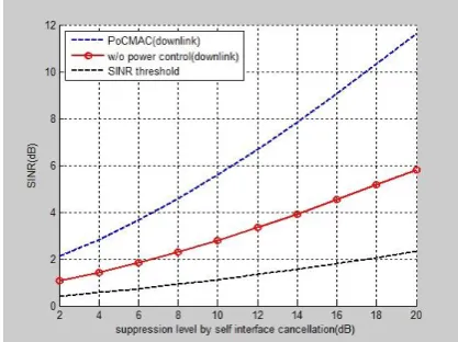
The simulation results are been compared between PoCMA(downlink), without power(downlink) and SNR threshold. These experimental results are obtained using matlab tool.
Fig 5. Number of clients
Fig 7. SNR vs Degree between Tx and Rx
Fig. 7 shows SINRUplink and SINRDownlink with respect tothe distance between the TX and the RX when the suppressionlevel of self-interference cancellation is 70 dB. In the caseof full-duplex without power control, SINRUplink does notchange as the distance between the TX and the RX increases,because it is not affected by the position of the RX. In contrast,SINRDownlink increases as the distance between the TX and theRX increases.
Fig 8. SNR vs Self Interference cancellation However, when an SINR threshold is required
to successfully receive the DATA transmission (e.g., we usean SINR threshold of around 6 dB in the simulations for thethroughput performance), the RX cannot receive the downlinktransmission owing to the low SINRDownlink in almost all positions.Thus, full-duplex without power control cannot utilizefull-duplex capability in this case.
Fig 9.Extension graph
The above fig 9 shows that the method CSM/CA based full duplex has better results compared to PocMAC
5. Conclusion:
A proposed full-duplex MAC protocol to give more prominent gathering chances to customers with low obstruction and to decrease the impedance amongst uplink and downlink transmissionsat the AP. For a given uplink transmission from a customer to the AP, a customer that can accomplish high SINR regardless of the concurrent uplink transmission may have a more prominent possibilityof being chosen as the downlink customer under the proposedRSSB conflict component. To expand the uplink and downlink SINRs, an improvement issue was planned, the ideal arrangement of which decides the transmit controlof the AP and the uplink customer. The characterized control outlines what's more, header structures to actualize our convention, PoCMAC. The execution of PoCMAC was assessed under different recreation
arrangements with respect to the SINR,
throughput,what's more, reasonableness. Moreover,
SDR-based examinations with WARP were
performed in a genuine remote correspondence condition. The recreation and examination comes about affirmed the amazing execution of PoCMAC. References:
[1] J. Choi, M. Jain, K. Srinivasan, P. Levis, and S. Katti, “Achieving singlechannel, full duplex wireless
communication,” in Proc. ACM Int.
Conf.MobiComNetw., 2010, pp. 1–12.
[2] M. Jain et al., “Practical, real-time, full duplex
wireless,” in Proc. ACMInt. Conf. MobiComNetw.,
[3] A. Sahai, G. Patel, and A. Sabharwal, “Pushing the limits of full-duplex:Design and real-time implementation,” Rice Univ., Houston, TX, USA,Rice Univ. Tech. Rep. TREE1104, 2011.
[4] M. Duarte, C. Dick, and A. Sabharwal, “Experiment-driven characterizationof full-duplex
wireless systems,” IEEE Trans. Wireless
Commun.,vol. 11, no. 12, pp. 4296–4307, Dec. 2012.
[5] M. Duarte et al., “Design and characterization of a
full-duplex multiantennasystem for WiFi networks,”
IEEE Trans. Veh. Technol., vol. 63,no. 3, pp. 1160–
1177, Mar. 2014.
[6] E. Everett, A. Sahai, and A. Sabharwal, “Passive
self-interference suppressionfor full-duplex
infrastructure nodes,” IEEE Trans.
WirelessCommun., vol. 13, no. 2, pp. 680–694, Feb.
2014.
[7] D. Bharadia, E. McMilin, and S. Katti, “Full
duplex radios,” in Proc. ACMSIGCOMM, 2013, pp.
375–386.
[8] S. Sen, R. Roy Choudhury, and S. Nelakuditi, “CSMA/CN: Carrier sensemultiple access with
collision notification,” in Proc. ACM Int.
Conf.MobiComNetw., 2010, pp. 25–36.
[9] K. Tamaki et al., “Full duplex media access
control for wireless multi-hopnetworks,” in Proc.
IEEE VTC—Spring, 2013, pp. 1–5.
[10] W. Zhou, K. Srinivasan, and P. Sinha, “RCTC: Rapid concurrent transmissioncoordination in full
duplex wireless networks,” in Proc. IEEE
ICNP,2013, pp. 1–10.
[11] W. Cheng, X. Zhang, and H. Zhang, “Optimal dynamic power control forfull-duplex
bidirectional-channel based wireless networks,” in Proc.
IEEEINFOCOM, 2013, pp. 3120–3128.
[12] S. Goyal, P. Liu, O. Gurbuz, E. Erkip, and S. Panwar, “A distributed MACprotocol for full duplex
radio,” in Proc. Asilomar Conf. Signals,
Syst.Comput., 2013, pp. 788–792.
[13] D. Ramirez and B. Aazhang, “Optimal routing and power allocation forwireless networks with
imperfect full-duplex nodes,” IEEE Trans.
WirelessCommun., vol. 12, no. 9, pp. 4692–4704,
Sep. 2013.
[14] N. Singh et al., “Efficient and fair MAC for
wireless networks with selfinterferencecancellation,”
in Proc. IEEE Int. Symp.ModelingWiOptMobile, Ad
Hoc Netw., 2011, pp. 94–101.
[15] J. Bai and A. Sabharwal, “Distributed
full-duplex via wireless sidechannels:Bounds and
protocols,” IEEE Trans.WirelessCommun., vol.
12,no. 8, pp. 4162–4173, Aug. 2013.
[16] A. Sahai, G. Patel, and A. Sabharwal,
“Asynchronous full-duplex wireless,”in Proc. Int.
Conf. COMSNETS, 2012, pp. 1–9.
[17] R. Jain, D. Chiu, and W. Hawe, “A quantitative measure of fairness anddiscrimination for resource allocation in shared computer system,” DigitalEquip. Corp., Hudson, MA, USA, DEC Tech. Rep. 301, 1984.