ISSN (Print) : 2320 – 3765 ISSN (Online): 2278 – 8875
I
nternational
J
ournal of
A
dvanced
R
esearch in
E
lectrical,
E
lectronics and
I
nstrumentation
E
ngineering
(A High Impact Factor & UGC Approved Journal)
Website: www.ijareeie.com
Vol. 6, Issue 9, September 2017
Active Power Limitation in PMSG-Based
Wind Turbines by Modified Back-To-Back
Converter during Different Grid Faults
G.Venkata Bhavana1, M.Naga Chaitra2
PG Student, Dept. of EEE, JNTUA College of Engineering, Andhra Pradesh, India1
Lecturer, Dept. of EEE, JNTUA College of Engineering, Andhra Pradesh, India2
ABSTRACT: Grid faults constitute the fundamental test for conveyed generation, particularly lasting magnet synchronous generator-based wind turbines associated with the grid by means of back to back (BTB) converters. Then again, grid codes implemented wind turbines to help arrange and fulfill lowvoltage ride-through (LVRT) necessities amid gridfaults. Dc-link overvoltage suppression without outside gadgets and reactive current injection to the grid in symmetrical and asymmetrical faults were the fundamental required subjects in various grid codes. Reactive current injection may prompt over-current in maybe a couple phases amid uneven faults. This paper introduced answers for finish LVRT necessities amid grid faults, including dc-link overvoltage suppression by enhancing BTB converter's controllers and the outline of dynamic control restriction to keep up the peak current of the grid side inverter in a protected range amid various asymmetricalgridfaults. Indeed, by controlling generation of PMSG dynamic power specifically with grid side inverter, the peak current stayed in the safe constrain and required responsive current, including negative-sequence segment can be injected to the grid. Moreover, the grid side active power swaying and dc-connect voltage swell can be smothered by utilizing the proposed controller. Conclusion comes about demonstrated the legitimacy and proficiently of the proposed control approach in various conditions.
I. INTRODUCTION
Wind energy is a quickly developing energy source among diverse sustainable power sources. As per the European windenergy affiliation (2020), wind control generation fulfills 18.4% of European Union power request [1]. Consequently, the penetration level of wind power control in the control grid has extensively developed. Along these lines, the grid code requires wind turbines to stay associated with the grid in distinctive voltage list conditions. Thus, the capacity of Low-Voltage Ride-Through (LVRT) is an essential issue in wind farms. An outline of the LVRT prerequisites in Danish grid code is appeared in Fig. 1 [2]. In spite of the fact that, there are distinctive sorts of wind turbines because of a few points of interest, direct driven Permanent Magnet Synchronous Generator (PMSG) based wind turbines are more alluring applicants on wind farms. In PMSG wind turbines, the gearbox can be dispensed with by expanding the number of poles. Besides, PMSG is associated with the gridby back to back (BTB) converters. Along these lines, this structure gives full controllability of the grid for Maximum Power Point Tracking (MPPT), executing LVRT and grid bolster [3].
An uncommon drop in the grid voltage result in a reduction in the exchanged power from the dc-link to the grid by the Grid Side Converter (GSC), in light of the fact that the converter current meets the maximum cutoff. In any case, the generation consistent to produce electric power. Subsequently, the dc-link voltage is exceptionally expanded. Besides, in asymmetricalgrid side voltage sags, the nearness of the negative-sequence voltage and current segments comes about the generation of the grid side active power and dc-link voltage second-order harmonic oscillations[4]-[6].
ISSN (Print) : 2320 – 3765 ISSN (Online): 2278 – 8875
I
nternational
J
ournal of
A
dvanced
R
esearch in
E
lectrical,
E
lectronics and
I
nstrumentation
E
ngineering
(A High Impact Factor & UGC Approved Journal)
Website: www.ijareeie.com
Vol. 6, Issue 9, September 2017
need to at the same time utilize at least two strategies. Also, the specified techniques are related with complex control structure in asymmetricalgridfaults.
As of late, altered BTB converter controller has been paid much consideration as a more appealing technique to enhance LVRT ability because of its proficient exhibitions in various faults what's more, ease. In ordinary controller, the dc-link voltage is controlled by GSC; and MPPT is actualized by Machine Side Converter (MSC). Consequently, MSC is unequipped for detecting the grid side issues, while the generator keeps on producing power. In any case, an adjustment in the control elements of BTB converters brings about the MSC controls the dc-connect voltage while GSC controls MPPT. Despite the fact that, this structure has great exhibitions in symmetrical faults; in any case, itshows poor activity in asymmetricalfaults. As indicated by, GSC just injects positive-sequencecomponents of currents to the grid to moderate current mutilations. Therefore, the injectedpower held second-orderharmonic motions.
Reference used dual current controller for positiveand negative-sequencecomponents. The dual present controller in GSC can moderate the second-orderharmonic of injectedactive power. In this technique, notwithstanding the positive sequence, the negative sequence of current is injectedto the grid. In spite of the fact that the positive and negative sequences of current have current limiters, But, finished current in one or two phases may happen in profound deviated faults then the security sequence of the inverter separates the wind turbine from the grid. Then again, to defeat this marvel, an expansion in the GSC current capacity will increment the cost. Likewise, by diminishing maximum cutoff of GSC present, second-order harmonics is added to the grid side activepower. In, the active and reactive power limiters were acquainted all together with wipe out finished current in the distributedgeneration (DG) inverters. In this structure, a crowbar was used to disseminate the surplus created power from DG. A few contemplates have presented distinctive techniques which actualized voltage bolster power for three-stage DG Inverters amid gridfaults. In every one of them, it was expected that DGs kept on producing active power and can't detect the gridfault. In this present work, notwithstanding power the produced active energy of PMSG by GSC in order to enhance the restriction execution of dc-link overvoltage, GSC injectsreactive current in grid side voltage droop conditions as indicated by the grid codes as appeared in Fig. 1(b).
This paper proposes another control procedure for direct driven MW-class high inertia PMSG based wind turbine working in distinctive conditions. In this structure, MPPT is executed by GSC, and MSC controls dc-link voltage. By utilizing this structure, the active crowbar in dc-connect is disposed of. Additionally, the dual present controller is intended for positive-and negativesequence segments for GSC keeping in mind the end goal to manage the unbalanced faults. As another commitment to prior investigations, this paper proposes another upper limiter to keep the peakcurrents of all phases in as far as possible. What's more, it grants the injection of the reactive current to the grid as indicated by the reactive current necessity of grid codes in symmetrical and awry grid issues. Indeed, by constraining the active power (active current), both negative sequence present and reactive current (as indicated by grid code) can be injected to the grid.
The limiters of active and reactive power references of GSC are ascertained in the grid voltage drop conditions. Subsequently, the PMSG keeps out from MPPT in voltage lists, and GSC can be worked as STATCOM. In this circumstance, mechanical part of turbine-generator goes about as a energy storage system. Thus, the speed of wind turbine is expanded (which is controlled by contribute point basic speed). It is significant here that this control technique is perfect with various grid codes. Besides, the proposed structure has great exhibitions in diverse sorts of lopsided faults. Besides, the grid side active power wavering and dc-link voltage ripple can be stifled by utilizing proposed controller. The paper is sorted out as takes after. Area II depicts the wind energy conversion model and the control plan of BTB. Area III presents estimation of proposed active control limiter. Area IV exhibits the investigation of operation. Segment V delineates the conclusion brings about distinctive gridfault conditions. At long last, the conclusion is exhibited in segment VI.
II. WIND ENERGY CONVERSION MODEL AND CONTROLLERS
The considered windenergyconversion comprises of four fundamental components: a wind turbine which extracts wind energy, PMSG which changes over mechanical power into electrical power, BTB converter which changes variable frequencysignal to gridfrequency by wanted alternatives, lastly a grid demonstrate (Fig. 2).
A. Wind Turbine
ISSN (Print) : 2320 – 3765 ISSN (Online): 2278 – 8875
I
nternational
J
ournal of
A
dvanced
R
esearch in
E
lectrical,
E
lectronics and
I
nstrumentation
E
ngineering
(A High Impact Factor & UGC Approved Journal)
Website: www.ijareeie.com
Vol. 6, Issue 9, September 2017
Pm=0.5ρπR2Cp(λ,β)vw3 (1)
where R is the span of cutting edges, ρ is the air thickness, vw is the wind speed and Cp(λ,β) is the turbine control conversion coefficient. β and λ are pitch point and tip speed proportion (TSR), individually. To remove greatest power from wind, the Cp ought to be set in greatest esteem (Cp-max), and the TSR is set to ideal esteem (λopt).
B. Modeling of PMSG and dc-link
The voltage conditions of a surface-mounted PMSG are given in synchronous d-q reference outline as [27]:
= + − (2)
= + + +ωgφ (3)
Fig.2.Simplified scheme of considered wind energy conversion system.
where Rs and Ls are the resistance and inductance of stator winding, Vds, Vqs, ids and iqs are the d-q segments of
stator voltage and current, separately.φ is the attractive flux and ωg is the electrical precise speed. The yield energy of
generator is given as:
=3
2 2 ⎸ ⎸ −
3
2 + (4)
where p is the pole number of generator and ωm is the pole speed. The dc-link voltage condition can be communicated
as:
2 = − ( ) (5)
C. Modeling of Grid
As appeared in Fig.2, the GSC is associated with the Point of common Coupling (PCC) by gridfaults and coupling
transformer. In unbalancedgrid voltage conditions, the positive-and negative-sequences voltage conditions are
communicated in the Asynchronous d-q facilitates as [4]:
= + + + (6)
= + − + (7)
Where Rf and Lf are the resistance and inductance of the gridfaults and coupling transformer, Edq, Vdq and Idq are the
GSC, PCC voltages and injected current to the grid in the synchronous d-q organizes, separately. The super records (+,
ISSN (Print) : 2320 – 3765 ISSN (Online): 2278 – 8875
I
nternational
J
ournal of
A
dvanced
R
esearch in
E
lectrical,
E
lectronics and
I
nstrumentation
E
ngineering
(A High Impact Factor & UGC Approved Journal)
Website: www.ijareeie.com
Vol. 6, Issue 9, September 2017
= + + (8)
Where the super record "*" speaks to a mind boggling conjugate esteem. Accordingly, the active power P(t)and
reactive power Q(t)are communicated as:
( ) = + 2 + sin 2 (9)
( ) = + cos 2 + sin 2 (10)
Where
= 1.5( + + + )
= 1.5 + + +
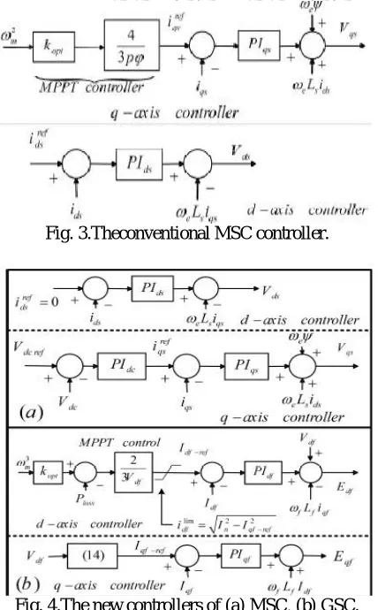
Fig. 3.Theconventional MSC controller.
Fig. 4.The new controllers of (a) MSC, (b) GSC.
= 1.5 − − +
= 1.5 − + −
= 1.5 − + −
ISSN (Print) : 2320 – 3765 ISSN (Online): 2278 – 8875
I
nternational
J
ournal of
A
dvanced
R
esearch in
E
lectrical,
E
lectronics and
I
nstrumentation
E
ngineering
(A High Impact Factor & UGC Approved Journal)
Website: www.ijareeie.com
Vol. 6, Issue 9, September 2017
D. MSC Controller
The MSC controller has two control loop as appeared in Fig.3 [26]. For the most part, the d-axis current reference is set to zero with a specific end goal to diminish the misfortunes in stator winding and keep away from demagnetization of changeless magnets. Customarily, the q-axis current reference is gotten to separate most extreme power from wind or accomplish smooth power and so on [26]. In this paper, linkvoltage reference is contrasted and the real dc-linkvoltage, and the distinction is bolstered into PI controller to accomplish the q-axis current reference (iqsref). Truth be told, q-axis controls dc-link voltage as appeared in Fig.4(a) [7]. Subsequently, when injectedgrid side active power is all of a sudden decreased due to voltage dip in the grid, the dc-link stays consistent.
E. GSC Controller
Like MSC controller, regular GSC controller has two control loops. The d-axisloop controls dc-link voltage what's more, the q-axisloop is utilized for reactive current injection or grid voltage bolster control [7]. Despite the fact that, in the new control structure, the generator control is controlled by GSC and reactive current is injected to the grid as per the grid codes as appeared in Fig.4 (b), yet it needs great execution in lopsided gridfaults. Henceforth, dual current controller for positive-and negativesequences is utilized to diminish dc-link overvoltage and secondorder components oscillations in injectedgridactive power [18]. To take out second-order segments oscillations of gridactive power, these two components (Pc2,Ps2)are set to zero. Keeping in mind the end goal to determine q components of positive-and negative-sequences of current references, (9) and (10) can be
The reactive power reference Q0 refcan be set by the grid prerequisites and the active power reference P0 refis resolved to separate most extreme power from wind. The active control reference P0
ref can be acquired from the articulation:
= −1.5 + −1.5 + (12)
ℎ = 0.5 _ /
III. PROPOSED ACTIVE POWER LIMITER
A. Issue Description
ISSN (Print) : 2320 – 3765 ISSN (Online): 2278 – 8875
I
nternational
J
ournal of
A
dvanced
R
esearch in
E
lectrical,
E
lectronics and
I
nstrumentation
E
ngineering
(A High Impact Factor & UGC Approved Journal)
Website: www.ijareeie.com
Vol. 6, Issue 9, September 2017
Fig.5.Trajectories of GSC current space vector.
Be that as it may, it should be utilized an outer gadget, for example, active crowbar in request to fulfill LVRT prerequisites. Consequently, this paper fulfills dc-link overvoltage suppression with no outside gadgets and proposes another active power limiter that executed the peak current impediment. Besides, by applying the new active power limiter, the limit of GSC was discharged and reactive current injected by LVRT necessity. Thus, peak current was constrained in safe bound (Ides) as appeared in Fig. 5.
B. Proposed Active Power Limiter
Right off the bat, it is expected that the greatest current of each stage ought to be not as much as Imax [21]:
max{ , , }≤ (13)
what's more, reactive current ought to be injected to the grid as indicated by Fig. 1(b). Besides, utilizing Park change for three-wire grid, at that point isolating positive-and negative-sequences segments of PCC voltage and GSC current, and furthermore utilizing (11) and appropriate meaning of reactive power reference Q0 ref, the positive-and negative-sequences currents can be inferred as:
= 2
3 ( " + ′ ) (14)
= 2
3 ( " − ′ ) (15)
= 2
3 (− " + ′ ) (16)
= 2
3 (− " − ′ ) (17)
where D is determinant of PCC voltage grid, and it is communicated as:
= ′ "
= ( − )( + ) (18)
what's more, Plim is the active power upper-limiter which ought to be decided. It ought to be noticed that the voltages of (18) is acquired as takes after:
= + , = +
Thirdly, to demonstrate the estimation of voltage unbalance, the voltage unbalance factor m is characterized as [23]:
ISSN (Print) : 2320 – 3765 ISSN (Online): 2278 – 8875
I
nternational
J
ournal of
A
dvanced
R
esearch in
E
lectrical,
E
lectronics and
I
nstrumentation
E
ngineering
(A High Impact Factor & UGC Approved Journal)
Website: www.ijareeie.com
Vol. 6, Issue 9, September 2017
At last, the aggregate of positive and negative esteems in d-q axis ought to be not as much as the most extreme estimation of GSC current. Consequently, the present impediment of GSC can be communicated as:
≥ + (20) ℎ ,
= + , = +
It is accepted that the GSC controller should deliver the negative-sequence current to adapt gridactive power second order part's oscillations. Subsequently, the negative-sequence current to positive-sequence current proportion ought to be equivalent to m what's more, is communicated as:
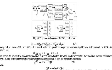
Fig. 6.The block diagram of GSC controller.
= / = / (21)
Subsequently, from (20) and (21), the most extreme positive-sequence current −max +delivered by GSC is acquired as:
= /(1 + ) (22)
Then again, to inject the adequate reactive current as indicated by grid code necessity, the reactive power reference (Q0ref) ought to be appropriately characterized; henceforth, it can be communicated as:
= 1.5√ " (23) Where
= +
As appeared in (13), by utilizing the square foundation of Dʹʹ rather than positive sequence of voltage, the negative part
of reactive power is considered. Thus, the normal estimation of reactive power increments. What's more, α is
characterized as the positive sequence of reactive current to evaluated GSC current proportion per PCC voltage accomplished from Fig. 1(b) and communicated as:
whereVdq-pu + is the per unit estimation of positive-sequence of d-q axis PCC voltage. Since, the proportion of Iq +-to
Imax in any event ought to be equivalent to α, the Q0refcan be revised as:
ISSN (Print) : 2320 – 3765 ISSN (Online): 2278 – 8875
I
nternational
J
ournal of
A
dvanced
R
esearch in
E
lectrical,
E
lectronics and
I
nstrumentation
E
ngineering
(A High Impact Factor & UGC Approved Journal)
Website: www.ijareeie.com
Vol. 6, Issue 9, September 2017
Note that the Q0ref definition in (25) has principle advantage. In reality, by supplanting α, the reactive current injection
can be actualized by various grid codes. Besides, by squaring the (20), it can be communicated as:
= (1 + ) (26)
Likewise, by embeddings (25) and (14)- (18) in (26), the active power impediment can be ascertained as takes after:
= (1− )
( ) −( ) (27)
In (27), this ought to be ((1+m2)- (1+m)2α2) ≥ 0. There are a few cases, for example, profound and high uneven voltage hangs that ((1+m2)- (1+m)2α2) < 0 and no sequence exist for (27). For case, accepting that the lopsided fault
happens in PCC there exist a voltage drop and voltage unbalance factor of over half and zero, separately. Thus, as
indicated by (24), α will be one. In any case, the (27) has no sequence on the grounds that ((1+m2)- (1+m)2α2) <0 . At
the end of the day, if the reactive power reference Q0 ref was characterized as (25), over current may happen in GSC. Subsequently, to keep this circumstance, the reactive power reference definition can be enhanced as:
= 1.5 αk (28)
Where κ is the reactive power reference factor and characterized as:
By characterizing Q0ref concurring (28), it is guaranteed that there is an existing answer for Plim in all conditions. The
reactive power reference factor, κ, limits the Q0 ref in profound lopsided voltage lists with a specific end goal to
anticipate over-current in GSC. Henceforth, by characterizing Q0 ref as per (28), the active power constraint can be enhanced as takes after:
From (30), it can be seen that Plim relies upon the most extreme current of GSC Imax, positive sequence of d-q axis of PCC voltage Vdqf +, voltage unbalance factor m, reactive power reference factor, κ, and reactive current to evaluated GSC current proportion per PCC voltage, α. It is imperative here that the PMSG active power is controlled by GSC
controller. Subsequently, by restricting injected GSC active power, the produced PMSG active power can be constrained and the active crowbar in dc-connection can be disposed of.
Likewise, the GSC can inject the conceivable reactive current to the grid in various gridfaults as indicated by grid code necessities. Besides, crest currents will be held in as far as possible. The square graph of GSC controller is appeared in Fig. 6.
IV. INVESTIGATION OF OPERATION
To approve the viability of the proposed active control limiter, three numerical illustrations have been
exhibited, and comes about are talked about of which the first what's more, second situations are asymmetricalfaults, and third is a symmetrical fault. The data of an average 1.5 MW PMSG-based wind turbine and grid attributes are given in Supplement. Henceforth, the principal situation expected that one-stage to ground fault happened with the accompanying PCC estimations: Vd +=429V, Vq +=0V, Vd - =-51V, and Vq - =127.7V. The peak of evaluated current of GSC is Imax=1775A.
= (1− )
( )−( ) (30)
From (19), (24), and (29), the voltage unbalance factor is m=0.3205, the reactive current to appraised GSC current
ISSN (Print) : 2320 – 3765 ISSN (Online): 2278 – 8875
I
nternational
J
ournal of
A
dvanced
R
esearch in
E
lectrical,
E
lectronics and
I
nstrumentation
E
ngineering
(A High Impact Factor & UGC Approved Journal)
Website: www.ijareeie.com
Vol. 6, Issue 9, September 2017
ref=413.84kVAr and active power constraint is Plim=699.24kW. Moreover, the greatest positive-sequence current that ought to be created by GSC is |Idq-max +|=1344.2A.
By substituting past information in (11) or (14)- (17), the d-q components of positive-and negative-sequences currents can be processed as: Id +=1211A, Iq +=-583.19A, Id - =317.57A, and Iq - =-291.16A. Concerning this situation, the reactive power reference factor of κ=1is worth specifying. It suggests that the reactive current can be injected by (24)
and the GSC current does not surpass from ostensible esteem.
V.FUZZY LOGIC CONTROLLER
FLC (Fuzzy Logic Controller) is nothing but set of rules.
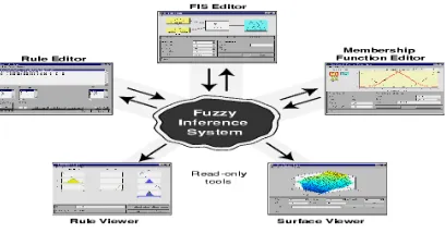
Fuzzy Logic Controller build by using the GUI(Graphical User Interface) tool and that is provided by the Fuzzy tool Box , It is used to build the system Graphically.
There are Five primary GUI tools for building, editing and observing the Fuzzy in Fuzzy tool Box.
There are Five Function ,They are
FIS Editor
MF Editor
Rule Editor
Rule Viewer
Surface Viewer
Fig .6.(c) Fuzzy controller over view.
(A) Fuzzy Interface System:
FIS is nothing but Fuzzy Interface System
In FIS editor it is shown that Input and Output Variable and we can gives the names to the input and output . We can taken input and output as per our Requirement and there is no limitations for input and output .
Between input and output we have a Fuzzy Logic Controller.
In that Fuzzy Logic Controller only we can write the rules and that rules are provided as per the paper or Project.
(B) Membership Function Editor:
In this we used to defines the shapes of the Membership Functions associated with each variable .
In this we can give the names for the MF .
We can change the range of X-axis but we can’t change the range of the Y-axis.
By default it will take as 0 to 1 .
For any MF X-axis takes as reference , Y Because we can the range of the X-axis as per our requirement.
(C) Rule Editor:
In this rule editor we can edit the rules and we can write the rules behavior . Depends on the rules only the total logic of the FL is Controlled.
We can able to change the rules here .
The number of rules are depends on the number of Membership Functions.
(D) Rule Viewer:
ISSN (Print) : 2320 – 3765 ISSN (Online): 2278 – 8875
I
nternational
J
ournal of
A
dvanced
R
esearch in
E
lectrical,
E
lectronics and
I
nstrumentation
E
ngineering
(A High Impact Factor & UGC Approved Journal)
Website: www.ijareeie.com
Vol. 6, Issue 9, September 2017
In this rule viewer we can able to see how the rules are built.
(E) Surface Viewer:
In this surface viewer
Rule viewer and Surface viewer are Strictly read only viewer
Advantages:
The ease to model your reasoning,
The ability to deal with uncertainty and nonlinearity;
The ease of implementation;
The use of linguistic variables.
VI.SIMULATION RESULTS
Fig. 8: (a) PCC voltage,
(b) PCC voltage in the synchronous d-q coordinates
(c) active power limitation (Plim), active power reference (P0ref), appliedactive power reference (Pgridref),
9.5 10 10.5 11
-2000 -1000 0 1000 2000
Time
V
a
,b,
c
(t
)
9.5 10 10.5 11 11.5 12
-200 0 200 400 600 800
Time
V
d
q
(V
)
9.5 10 10.5 11 11.5 12
0 0.5 1 1.5
Time
P
(M
W
ISSN (Print) : 2320 – 3765 ISSN (Online): 2278 – 8875
I
nternational
J
ournal of
A
dvanced
R
esearch in
E
lectrical,
E
lectronics and
I
nstrumentation
E
ngineering
(A High Impact Factor & UGC Approved Journal)
Website: www.ijareeie.com
Vol. 6, Issue 9, September 2017
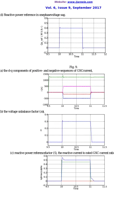
(d) Reactive power reference in onephasevoltage sag.
Fig. 9.
(a) the d-q components of positive- and negative-sequences of GSCcurrent,
(b) the voltage unbalance factor (m),
(c) reactive power referencefactor (κ), the reactive current to rated GSC current ratio (Iq/Imax) and(α).
9.5 10 10.5 11 11.5 12
-0.1 0 0.1 0.2 0.3 0.4 0.5 0.6
Time
Q
o
_
re
f
(
M
V
A
r
)
9.5 10 10.5 11 11.5
-1000 -500 0 500 1000 1500
Time
I
[A
]
9.5 10 10.5 11 11.5
0 0.1 0.2 0.3 0.4
Time
m
9.5 10 10.5 11 11.5
-0.1 0 0.1 0.2 0.3 0.4 0.5 0.6
Time
Iq
/I
m
a
x
,k
,a
lp
h
ISSN (Print) : 2320 – 3765 ISSN (Online): 2278 – 8875
I
nternational
J
ournal of
A
dvanced
R
esearch in
E
lectrical,
E
lectronics and
I
nstrumentation
E
ngineering
(A High Impact Factor & UGC Approved Journal)
Website: www.ijareeie.com
Vol. 6, Issue 9, September 2017
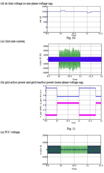
(d) dc-link voltage in one-phase voltage sag.
Fig. 10. (a) Grid side current,
(b) grid active power and grid reactive power inone-phase voltage sag.
Fig. 11 (a) PCC voltage,
9.5 10 10.5 11 11.5
-500 0 500 1000 1500 2000
Time
V
d
c
[V
]
9.5 10 10.5 11 11.5 12
-3000 -2000 -1000 0 1000 2000 3000
Time
I
a
,b
,c
(
t)
[A
]
9.5 10 10.5 11 11.5 12
-0.2 0 0.2 0.4 0.6 0.8 1 1.2
Time
P
_
g
ri
d
(M
W
)
,
Q
_
g
ri
d
(M
V
A
r
)
9.5 10 10.5 11 11.5
-2000 -1000 0 1000 2000
Time
V
a
,b
,c
(
ISSN (Print) : 2320 – 3765 ISSN (Online): 2278 – 8875
I
nternational
J
ournal of
A
dvanced
R
esearch in
E
lectrical,
E
lectronics and
I
nstrumentation
E
ngineering
(A High Impact Factor & UGC Approved Journal)
Website: www.ijareeie.com
Vol. 6, Issue 9, September 2017
(b) PCC voltage in the synchronous d-q coordinates
(c) active power limitation (Plim), active power reference (P0ref), appliedactive power reference (Pgridref),
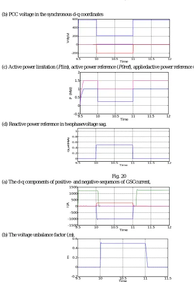
(d) reactive power reference in twophasevoltage sag.
Fig.12. (a)d-q components of positive- and negative-sequences of GSC current
9.5 10 10.5 11 11.5 12
-200 0 200 400 600
Time
V
d
q
(V
)
9.5 10 10.5 11 11.5 12
-0.5 0 0.5 1 1.5 2
Time
P
(M
W
)
9.5 10 10.5 11 11.5 12
-0.2 0 0.2 0.4 0.6
Time
Q
o
_
re
f
(
M
V
A
r
)
9.5 10 10.5 11 11.5 12
-1500 -1000 -500 0 500 1000 1500
Time
I
[A
ISSN (Print) : 2320 – 3765 ISSN (Online): 2278 – 8875
I
nternational
J
ournal of
A
dvanced
R
esearch in
E
lectrical,
E
lectronics and
I
nstrumentation
E
ngineering
(A High Impact Factor & UGC Approved Journal)
Website: www.ijareeie.com
Vol. 6, Issue 9, September 2017
(b)voltage unbalance factor (m),
(c) Reactive power referencefactor (κ) the reactive current to rated GSC current ratio (Iq+-/Imax) and (α).
(d) dc-link voltage in two-phase voltage sag.
Fig.13. (a) Grid side current,
9.5 10 10.5 11 11.5
-0.2 0 0.2 0.4 0.6
Time
m
9.5 10 10.5 11 11.5
-0.5 0 0.5 1 1.5
Time
Iq
/Imax
, k
, A
lpha
9.5 10 10.5 11 11.5
-500 0 500 1000 1500 2000
Time
V
d
c
[V
]
9.5 10 10.5 11 11.5 12
-2000 -1000 0 1000 2000
Time
I
a
,b
,c
(
t)
[
A
ISSN (Print) : 2320 – 3765 ISSN (Online): 2278 – 8875
I
nternational
J
ournal of
A
dvanced
R
esearch in
E
lectrical,
E
lectronics and
I
nstrumentation
E
ngineering
(A High Impact Factor & UGC Approved Journal)
Website: www.ijareeie.com
Vol. 6, Issue 9, September 2017
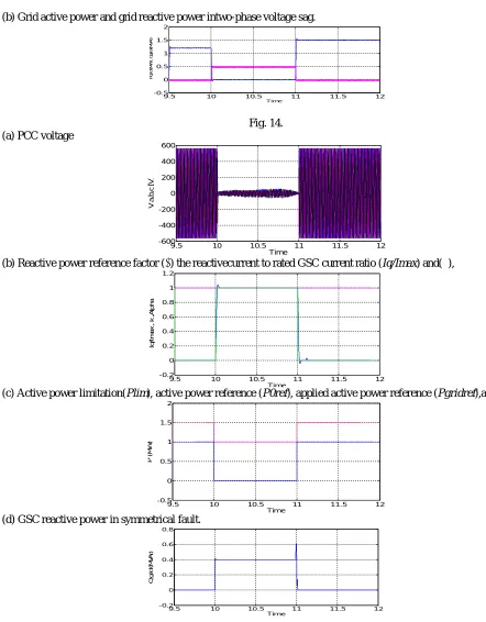
(b) Grid active power and grid reactive power intwo-phase voltage sag.
Fig. 14. (a) PCC voltage
(b) Reactive power reference factor (κ) the reactivecurrent to rated GSC current ratio (Iq/Imax) and(α),
(c) Active power limitation(Plim), active power reference (P0ref), applied active power reference (Pgridref),and
(d) GSC reactive power in symmetrical fault.
9.5 10 10.5 11 11.5 12
-0.5 0 0.5 1 1.5 2 Time P g ri d ( M W ) , Q g ri d ( M V A r)
9.5 10 10.5 11 11.5 12
-600 -400 -200 0 200 400 600 Time V a ,b ,c [ V ]
9.5 10 10.5 11 11.5 12
-0.2 0 0.2 0.4 0.6 0.8 1 1.2 Time Iq /I m a x , k , A lp h a
9.5 10 10.5 11 11.5 12
-0.5 0 0.5 1 1.5 2 Time P ( M W )
9.5 10 10.5 11 11.5 12
ISSN (Print) : 2320 – 3765 ISSN (Online): 2278 – 8875
I
nternational
J
ournal of
A
dvanced
R
esearch in
E
lectrical,
E
lectronics and
I
nstrumentation
E
ngineering
(A High Impact Factor & UGC Approved Journal)
Website: www.ijareeie.com
Vol. 6, Issue 9, September 2017
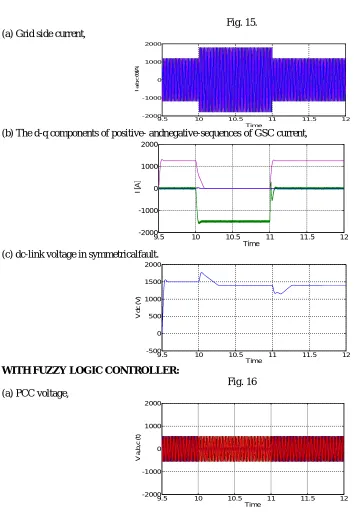
Fig. 15. (a) Grid side current,
(b) The d-q components of positive- andnegative-sequences of GSC current,
(c) dc-link voltage in symmetricalfault.
WITH FUZZY LOGIC CONTROLLER:
Fig. 16 (a) PCC voltage,
9.5 10 10.5 11 11.5 12
-2000 -1000 0 1000 2000
Time
I
a
,b
,c
(
t)
[A
]
9.5 10 10.5 11 11.5 12
-2000 -1000 0 1000 2000
Time
I
[A
]
9.5 10 10.5 11 11.5 12
-500 0 500 1000 1500 2000
Time
V
d
c
(
V
)
9.5 10 10.5 11 11.5 12
-2000 -1000 0 1000 2000
Time
V
a
,b
,c
(
ISSN (Print) : 2320 – 3765 ISSN (Online): 2278 – 8875
I
nternational
J
ournal of
A
dvanced
R
esearch in
E
lectrical,
E
lectronics and
I
nstrumentation
E
ngineering
(A High Impact Factor & UGC Approved Journal)
Website: www.ijareeie.com
Vol. 6, Issue 9, September 2017
(b) PCC voltage in the synchronous d-q coordinates
(c) Active power limitation (Plim), active power reference (P0ref), appliedactive power reference (Pgridref),
(d) Reactive power reference in onephasevoltage sag.
Fig.17. (a)d-q components of positive- and negative-sequences of GSCcurrent,
(b)voltage unbalance factor (m),
9.5 10 10.5 11 11.5 12
-200 0 200 400 600 800
Time
V
d
q
(
V
)
9.5 10 10.5 11 11.5 12
0 0.5 1 1.5 2
Time
P
(
M
W
)
9.5 10 10.5 11 11.5 12
-0.2 0 0.2 0.4 0.6
Time
Q
o
_
re
f
(M
V
A
r)
9.5 10 10.5 11 11.5 12
-1000 -500 0 500 1000 1500
Time
I
[A
]
9.5 10 10.5 11 11.5 12
-0.1 0 0.1 0.2 0.3 0.4
ISSN (Print) : 2320 – 3765 ISSN (Online): 2278 – 8875
I
nternational
J
ournal of
A
dvanced
R
esearch in
E
lectrical,
E
lectronics and
I
nstrumentation
E
ngineering
(A High Impact Factor & UGC Approved Journal)
Website: www.ijareeie.com
Vol. 6, Issue 9, September 2017
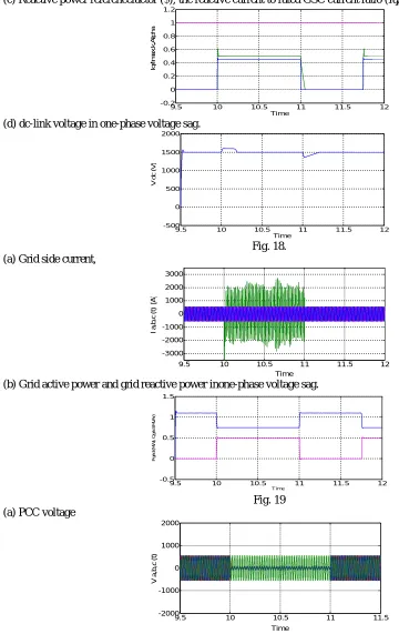
(c) Reactive power referencefactor (κ), the reactive current to rated GSC current ratio (Iq/Imax) and(α).
(d) dc-link voltage in one-phase voltage sag.
Fig. 18. (a) Grid side current,
(b) Grid active power and grid reactive power inone-phase voltage sag.
Fig. 19 (a) PCC voltage
9.5 10 10.5 11 11.5 12
-0.2 0 0.2 0.4 0.6 0.8 1 1.2 Time Iq /I m a x ,k ,A lp h a
9.5 10 10.5 11 11.5 12
-500 0 500 1000 1500 2000 Time V d c ( V )
9.5 10 10.5 11 11.5 12
-3000 -2000 -1000 0 1000 2000 3000 Time I a ,b ,c ( t) [A ]
9.5 10 10.5 11 11.5 12
-0.5 0 0.5 1 1.5 Time P g ri d ( M W ), Q g ri d ( M V A r)
9.5 10 10.5 11 11.5
ISSN (Print) : 2320 – 3765 ISSN (Online): 2278 – 8875
I
nternational
J
ournal of
A
dvanced
R
esearch in
E
lectrical,
E
lectronics and
I
nstrumentation
E
ngineering
(A High Impact Factor & UGC Approved Journal)
Website: www.ijareeie.com
Vol. 6, Issue 9, September 2017
(b) PCC voltage in the synchronous d-q coordinates
(c) Active power limitation (Plim), active power reference (P0ref), appliedactive power reference (Pgridref),
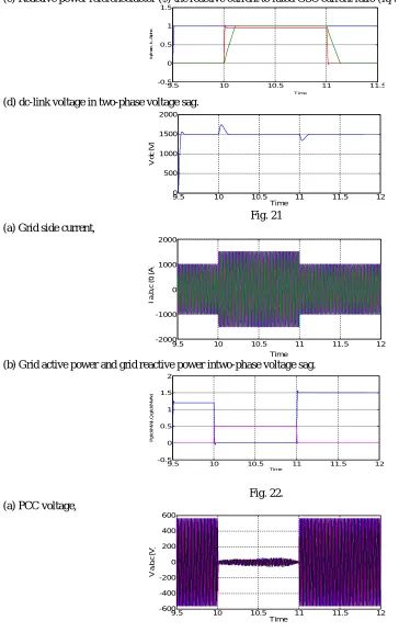
(d) Reactive power reference in twophasevoltage sag.
Fig. 20
(a) The d-q components of positive- and negative-sequences of GSCcurrent,
(b) The voltage unbalance factor (m),
9.5 10 10.5 11 11.5 12
-200 0 200 400 600
Time
V
d
q
(
v
)
9.5 10 10.5 11 11.5 12
-0.5 0 0.5 1 1.5 2
Time
P
(M
W
)
9.5 10 10.5 11 11.5 12
0 0.2 0.4 0.6 0.8 1
Time
Q
o
_
re
f
(M
V
A
r)
9.5 10 10.5 11 11.5 12
-1500 -1000 -500 0 500 1000 1500
Time
I
[A
]
9.5 10 10.5 11 11.5
-0.2 0 0.2 0.4 0.6
Time
ISSN (Print) : 2320 – 3765 ISSN (Online): 2278 – 8875
I
nternational
J
ournal of
A
dvanced
R
esearch in
E
lectrical,
E
lectronics and
I
nstrumentation
E
ngineering
(A High Impact Factor & UGC Approved Journal)
Website: www.ijareeie.com
Vol. 6, Issue 9, September 2017
(c) Reactive power referencefactor (κ) the reactive current to rated GSC current ratio (Iq+-/Imax) and (α),
(d) dc-link voltage in two-phase voltage sag.
Fig. 21 (a) Grid side current,
(b) Grid active power and grid reactive power intwo-phase voltage sag.
Fig. 22. (a) PCC voltage,
9.5 10 10.5 11 11.5
-0.5 0 0.5 1 1.5 Time Iq /I m a x , k , A lp h a
9.5 10 10.5 11 11.5 12
0 500 1000 1500 2000 Time V d c ( V )
9.5 10 10.5 11 11.5 12
-2000 -1000 0 1000 2000 Time I a ,b ,c ( t) [ A ]
9.5 10 10.5 11 11.5 12
-0.5 0 0.5 1 1.5 2 Time P g ri d ( M W ) ,Q g ri d ( M V A r)
9.5 10 10.5 11 11.5 12
ISSN (Print) : 2320 – 3765 ISSN (Online): 2278 – 8875
I
nternational
J
ournal of
A
dvanced
R
esearch in
E
lectrical,
E
lectronics and
I
nstrumentation
E
ngineering
(A High Impact Factor & UGC Approved Journal)
Website: www.ijareeie.com
Vol. 6, Issue 9, September 2017
(b) Reactive power reference factor (κ) the reactivecurrent to rated GSC current ratio (Iq/Imax) and(α),
(c) Active power limitation(Plim), active power reference (P0ref), applied active power reference (Pgridref),and
(d) GSC reactive power in symmetrical fault.
Fig. 23. (a) Grid side current,
(b) the d-q components of positive- andnegative-sequences of GSC current, and
9.5 10 10.5 11 11.5 12
-0.2 0 0.2 0.4 0.6 0.8 1 1.2
Time
Iq
/I
m
a
x
,k
,A
lp
h
a
9.5 10 10.5 11 11.5 12
0 0.5 1 1.5 2
Time
P
(
M
W
)
9.5 10 10.5 11 11.5 12
-0.2 0 0.2 0.4 0.6 0.8
Time
Q
g
ri
d
(
M
V
A
r)
9.5 10 10.5 11 11.5 12
-2000 -1000 0 1000 2000
Time
I
a
,b
,c
(
t)
[A
]
9.5 10 10.5 11 11.5 12
-2000 -1500 -1000 -500 0 500 1000 1500
Time
I
[A
ISSN (Print) : 2320 – 3765 ISSN (Online): 2278 – 8875
I
nternational
J
ournal of
A
dvanced
R
esearch in
E
lectrical,
E
lectronics and
I
nstrumentation
E
ngineering
(A High Impact Factor & UGC Approved Journal)
Website: www.ijareeie.com
Vol. 6, Issue 9, September 2017
(c) dc-link voltage in symmetricalfault.
THD Comparison Table:
S.No Fault Type THD
for Propos
ed PI control ler (%)
THD for Fuzzy controll er (%).
1. One Phase Voltage Sag
Voltage 7.14 0.43
Current 7.13 0.43 2. Two Phase
Voltage Sag
Voltage 7.14 0.42
Current 7.14 0.42 3. Symmetrica
l Fault
Voltage 7.14 0.42 Current 7.14 0.42
VII. CONCLUSION
A novel control strategy for the operation of direct driven Permanent Magnet Synchronous Generator (PMSG) based grid connected wind turbine has been proposed. Fuzzy logic controller have shown better performance than the other controllers since it controls pitch angle, real and reactive power flows of grid connected direct driven PMSG system. The results obtained for different faults were only shown for simplicity. Moreover, the active performance is verified under three different faults they are one phase and two phase and symmetrical faults. Finally, it is concluded that the proposed system can be a cost-effective solution to achieve the requirements of new wind farm grid code and these results shows that the PMSG system has superior performance .
.
REFERENCES
[1] EWEA, EU Energy Policy to 2050 – Achieving 80-95% emissionsreductions. A report by the European Wind Energy Association, Mar.2011. [2] Energinet. Technical regulation 3.2.5 for wind power plants with apower output greater than 11kW. Sep. 2010. Available at:http://www.energinet.dk.
[3] M. EnamulHaque, Y. C. Saw, and M. M. Chowdhury, “AdvancedControl Scheme for an IPM Synchronous Generator-Based GearlessVariable Speed Wind Turbine,” IEEE Trans. Sustain. Energy, vol. 5, no.2, pp. 354-362, Apr. 2014.
[4] H. –S. Song and K. Nam, “Dual current control scheme for PWMconverter under unbalanced input voltage conditions,” IEEE Trans. Ind.Appl., vol. 46, no. 5, pp. 953-959, Oct. 1999.
9.5 10 10.5 11 11.5 12
0 500 1000 1500 2000
Time
V
d
c
(
V