Modeling Of a Pv Cell For Maximum Tracking For Energy Control
With Srm Drive
B. Bhaskar, M.V. Rambabu, G. Rajkumar
Department of EEE, CITS Warangal, Telangana.
Mail id:[email protected], [email protected], [email protected]
ABSTRACT: -
Electric vehicles are automobiles, which are powered by electrical engine and electrical energy. Due to the limitation of current battery technologies, the driving range is very short. In earlier, in terms of motor drives, high performance permanent-magnet (PM) machines are widely used. In PM machines there is no field winding and the field is provided by the permanent magnet. Most commonly rare earth materials are used. But they are very costlier. To overcome these issues a photovoltaic panel and a switched reluctance motor can be used for power supply and motor drive. In order to decrease the energy conversion processes, one approach is to redesign the motor to include some onboard charging functions. The solar energy utilization and maximum power point tracking (MPPT) are the unique factors for the PV-fed electric vehicles. In order to achieve low-cost and flexible energy flow modes, a novel low-cost tri-port converter is proposed in this paper in order to coordinate the PV panel, SRM, and battery. To support flexible control of energy flow six operational modes are developed.
KEYWORDS: Electric vehicles, photovoltaic, maximum power point tracking, switched reluctance motors (SRMs), tri-port Converter
I. INTRODUCTION
Electric vehicles are automobiles, which are powered by electrical engine and electrical energy. An electric vehicle (EV), also referred to as an electric drive vehicle, uses one or more electric motors or traction motors for propulsion. An electric vehicle may be powered through a collector system by electricity from off-vehicle sources, or may be selfcontained with a battery or generator to convert fuel to electricity. EVs include road and rail vehicles, surface and underwater vessels, electric aircraft and electric spacecraft. EVs first came into existence in the mid-19th century, when electricity was among the preferred methods for motor vehicle propulsion, providing a level of comfort and ease of operation that could not be achieved by the gasoline cars of the time. The development of electric
the wide application of electric vehicles. To overcome these issues a photovoltaic panel and a switched reluctance motor can be used for power supply and motor drive [3]. By introducing PV panel on the top of the vehicle, a suitable energy source can be achieved. PV panel has low power density for traction drives; they can be used to charge the batteries. Also the SRM need no rare earth materials. The switched reluctance motor (SRM) is a type of a stepper motor, an electric motor that runs by reluctance torque [1]. Unlike common DC motor types, power is delivered to windings in the stator (case) rather than the rotor. This greatly simplifies mechanical design as power does not have to be delivered to a moving part, but it complicates the electrical design as some sort of switching system needs to be used to deliver power to the different windings. With modern electronic devices, precisely timed switching is not a problem, and the SRM is a popular design for modern stepper motors. Its main drawback is torque ripple. In order to decrease the energy conversion processes, one approach is to redesign the motor to include some onboard charging functions. The performance of battery modules depends not only on the design of the modules but on how the modules are used and charged as well. In this sense, battery chargers play a critical role in the evolution of this technology [2]. Generally, battery chargers are classified into the following two types:
1) The onboard type and
2) The stand-alone (off board) type.
Because the onboard type of chargers should always be carried by the vehicle, the weight and space, as well as the cost, have to be minimized. Thus, it is normally not practical to have a high-power level of the onboard chargers with galvanic isolation. Although isolation is a very favorable option in the charger circuits for safety reasons it is usually avoided due to its cost impact on the
system. Off board chargers are located at a fixed location. They are limited in their power output by the ability of the battery to accept the charge. The maximum power point tracking (MPPT) and solar energy utilization are the unique factors for the PV-fed EVs. In order to achieve low-cost and flexible energy flow modes, a low-cost tri-port converter can be used to coordinate the PV panel, SRM, and battery.
Conventional PV fed EV system
The renewable energy is vital for today’s world as in near future the non-renewable sources that we are using are going to be get exhausted. The solar vehicle is a step in saving the non-renewable sources of energy. The basic principle of solar car is to use energy that is stored in the battery during and after charging it from a solar panel. The charged batteries are used to drive the motor which serves here as an engine. Energy is one of the most vital needs for human survival on the earth. We are dependent on one form of energy or the other form for
fulfilling our needs.
Fig.1 Basic block Diagram Representation of Solar vehicle
charged and there after they are charged by panels. This helps in completing the charging-discharging cycle of the batteries, which is very important for proper working of batteries. DC motors were the preferred option in variable-speed operation applications before the development of advanced power electronics. The main disadvantages are low power density compared with alternative technologies, costly maintenance of the coal brushes (about every 3000 h), and low efficiency, although efficiency values over 85% are feasible. DC motors still have a wide market of lower and middle power range commutation vehicles. In earlier, in terms of motor drives, high-performance permanent-magnet (PM) machines are widely used. In PM machines there is no field winding and the field is provided by the permanent magnet. Most commonly rare earth materials are used. But they are very costlier. So by the use of PM machines it will also reduce the wide application of electric vehicles.
II. PROPOSED SYSTEM
The proposed system will helps to achieve low-cost and flexible energy flow modes. For this a low-cost tri-port converter can be used to coordinate the PV panel, SRM, and battery.
Fig.2 Proposed tri-port topology for PV-powered SRM drive
The proposed tri-port topology consist of three energy terminals, PV, battery, and SRM. The three are linked by a power converter that consists of four switching devices (S0 − S3), four diodes (D0 − D3), and two relays J1 and J2, as
shown in Fig. 2.
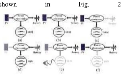
Fig.3 Six operation modes of the proposed tri-port topology. (a) Mode 1. (b) Mode 2. (c) Mode 3. (d) Mode 4. (e) Mode 5.
(f) Mode 6.
In mode 1, PV act as the energy source to drive the SRM and to charge the battery. In mode 2, the battery and PV are both the energy sources to drive the SRM. In mode 3, PV is the source and the battery is idle. In mode 4, the PV is idle and the battery is the driving source. In mode 5, the battery is charged by a single-phase grid and both the PV and SRM are idle. And in mode 6, the battery is charged by the PV and SRM is idle.
DRIVING MODES
Operating modes 1–4 are the driving modes to provide traction drive to the vehicle.
1) Mode 1: In this mode relay J1 turns off
and relay J2 turns on. The PV panel energy feeds the energy to SRM and charges the battery; so in this mode, the battery is charged.
2) Mode 2: When the SRM operates in
heavy load, both the PV panel and battery supply power to the SRM. Here the
relay J1 and J2 are turned on.
3) Mode 3: When the battery is out of
power, the PV panel is the energy source to drive the vehicle. Here the J1 turns on and J2 turns off.
4) Mode 4: When the PV cannot generate
electricity due to low solar irradiation, the battery supplies power to the SRM. The corresponding topology is illustrated in Fig.3.6. In this mode, relay J1 and J2 are both conducting.
Fig: 5 Mode 3 and 4
5) Mode 5: When PV cannot generate
electricity then an external power source is needed to charge the battery. In this
modeJ1 and J2 turn on. Point A is central tapped of phase windings. Here phase windings La1 and La2 are employed as input filter inductors.
Fig: 6 Mode 5 and 6
6) Mode 6: When the EV is parked under
the sun, then the PV can charge the battery. In this mode J1 turns off and J2
turns on.
III. GRID-CHARGING CONTROL STRATEGY
The proposed topology also supports the single-phase grid charging. There are four basic charging states and S0 is
always turned off in this condition.
Fig: 7 Grid charging state 1 and 2
In grid charging state 1, the grid voltage charges the phase winding La2, the corresponding equation can be expressed as; Ugrid= La2 . In grid charging state 2, S1 turns off and S2 conducts, the grid is connected in series with phase winding to charges the battery, the corresponding equation can be expressed as; UB - Ugrid= La2 .
Fig: 8 Grid charging state 3 and 4
In grid charging state 3, S1 and S2 conduct, the grid voltage charges the phase winding
La1 and La2, the corresponding equation can be expressed as; Ugrid= U1 + U2
PV-FED CHARGING CONTROL
STRATEGY
In this mode, the PV panel charges the battery directly by the driving topology. The phase windings are employed as
inductor and the driving topology can be functioned as interleaved buck–boost charging topology.
Fig: 9 PV fed charging mode
For one phase, there are two states, as shown in Fig: 9. When S0 and S1 turn on, the PV panel charges phase inductance; when S0 and S1 turn off, the phase inductance discharges energy to the battery. According to the state-ofcharging (SoC), there are three stages to make full use of solar energy and also it will maintain the battery healthy condition. During stage 1, the battery is in extremely in the lack energy condition, the MPPT control strategy is employed to make full use of solar energy. During stage 2, the constant-voltage control is adopted to charge the battery.
Fig.10. Current Wave forms
Fig.11. Torque Speed characteristics of three phase currents
IV. CONCLUSION
earth materials are used. But they are very costlier. So by the use of PM machines it will also reduce the wide application of electric vehicles. To overcome these issues a photovoltaic panel and a switched reluctance motor can be used for power supply and motor drive. A tri-port converter is used to coordinate the PV panel, battery, and SRM. Six working modes are developed to achieve flexible energy flow for driving control, driving/charging hybrid control, and charging control. A PV-fed battery charging control scheme is developed to improve the solar energy utilization. Since PV-fed EVs are a greener and more sustainable technology than conventional ICE vehicles, this work will provide a feasible solution to reduce the total costs and CO2 emissions of electric vehicles.
REFERENCES
[1] Yihua Hu, Chun Gan, and Wenping Cao, “Solar PV powered SRM drive for Evs with flexible energy control functions,” IEEE Trans. Ind. Electron., vol. 52, no. 4, pp. 1063–1070, July/Aug.2016.
[2] A. Emadi, L. Young-Joo, and K. Rajashekara, “Power electronics and motor drives in electric, hybrid electric, and plug-in hybrid electric vehicles,” IEEE Trans. Ind. Electron., vol. 55, no. 6, pp. 2237–2245, Jun.2008.
[3] A. Kuperman, U. Levy, J. Goren, A. Zafransky, and A. Savernin, “Battery charger for electric vehicle traction battery switch station,” IEEE Trans. Ind. Electron., vol. 60, no. 12, pp. 5391–5399, Dec. 2013. [4] Y. Hu, C. Gan, W. Cao, W. Li, and S. Finney, “Central-tapped node linked modular fault tolerance topology for SRM based EV/HEV applications,” IEEE Trans. Power Electron., vol. 31, no. 2, pp. 1541– 1554, Feb. 2016.
[5] Y. Hu, X. Song, W. Cao, and B. Ji, “New SR drive with integrated charging
capacity for plug-in hybrid electric vehicles (PHEVs),” IEEE Trans. Ind. Electron., vol. 61, no. 10, pp. 5722–5731. Oct. 2014. [6] S. G. Li, S. M. Sharkh, F. C.Walsh, and C. N. Zhang, “Energy and battery management of a plug-in series hybrid electric vehicle using fuzzy logic,” IEEE Trans. Veh. Technol., vol. 60, no. 8, pp. 3571–3585, Oct. 2011.
[7] H. Kim, M. Y. Kim, and G. W. Moon, “A modularized charge equalizer using battery monitoring IC for series-connected Li-ion battery strings in electric vehicles,” IEEE Trans. Power Electron., vol. 28, no. 8, pp. 3779–3787, May 2013.
[8] Ping, Z. Jing, L. Ranran, T. Chengde, and W. Qian, “Magnetic characteristics investigation of an axial–axial flux compound-structure PMSM used for HEVs,” IEEE Trans. Magn., vol. 46, no. 6, pp. 2191–2194, Jun. 2010.
[9] A. Kolli, O. Béthoux, A. De Bernardinis, E. Labouré, and G. Coquery, “Space-vector PWM control synthesis for an H-bridge drive in electric vehicles,” IEEE Trans. Veh. Technol., vol. 62, no. 6, pp. 2441–2452, Jul. 2013.
[10] Y. Hu, C. Gan, W. Cao, W. Li, and S. Finney, “Central-tapped node linked modular fault tolerance topology for SRM based EV/HEV applications,” IEEE Trans. Power Electron., vol. 31, no. 2, pp. 1541– 1554, Feb. 2016.
[11] S. M. Yang and J. Y. Chen, “Controlled dynamic braking for switched reluctance motor drives with a rectifier front end,” IEEE Trans. Ind.Electron., vol. 60, no. 11, pp. 4913–4919, Nov. 2013.
[12] B. Bilgin, A. Emadi, and M. Krishnamurthy, “Comprehensive evaluation of the dynamic performance of a 6/10 SRM for traction application in PHEVs,” IEEE Trans. Ind. Electron., vol. 60, no. 7, pp. 2564–2575, Jul. 2013.
“Test results and torque improvement of the 50-kW switched reluctance motor designed for hybrid electric vehicles,” IEEETrans. Ind. Appl., vol. 48, no. 4, pp. 1327 1334, Jul./Aug. 2012.
[14] A. Chiba, M. Takeno, N. Hoshi, M. Takemoto, S. Ogasawara, and M. A.Rahman, “Consideration of number of series turns in switched