Microstructure and Microwave Absorption Properties of
Flame Sprayed Ceramic Coatings
Gagan Deep Aul
1, Vikas Chawla
2,
Santosh K Vishvakarma
31
Research Scholar, IKGPTU, Jalandhar, Punjab, (India)
2
Professor, Mechanical Engineering, IKGPTU, Jalandhar, Punjab, (India)
3
Associate Professor, Electrical Engineering, IIT, Indore (India)
ABSTRACT
In this research work, airplane grade aluminum alloy substrate was coated by Al2O3/ TiO2 ceramic coatings in
two different compositions as 50:50 and 87:13 using Flame spraying technique. The surface & cross-sectional
morphological characterizations of the Al2O3/ TiO2 powders and coatings were performed by scanning electron
microscopy (SEM). The microwave absorbing properties of coatings were experimentally investigated using
vector network analyzer in the frequency range from 8.2 to 12.4 GHz (X-band). The reflection loss values of
Al2O3/ TiO2 coatings in 50:50 composition exceeding 10 dB (larger than 90% absorption) was achieved in the
frequency range 9.28GHz to 9.82GHz with maximum reflection loss of -11.936dB at 9.53 GHz. It is observed
that 87:13 composition of the ceramics Al2O3/ TiO2, gives more than 90% absorption in the frequency range
9.32GHz to 10.21 GHz with a reflection loss peak of -13.6 GHz at 9.683GHz.
Keywords :
Radar Absorbing Material, Flame Spray, Coatings.
1.
INTRODUCTION
Due to rapid advancements in the stealth technology, the RAM demands to be thin, lightweight and should be
able to possess good reflection loss in the broader range of frequencies. Till today it is a thought-provoking task
to develop a thin broadband absorber with improved reflection loss because of stronger trade-off in thickness
and bandwidth. Research in development of electromagnetic absorbing coatings /materials gets widespread
publicity as its requirement in stealth, EM interference shielding and many more [3-7].
When an EM wave front impinges on a body, part of the energy associated with the wave could get absorbed
depending upon the nature of the surface. The rest of the incident energy can then be accounted for, by the
phenomena of reflection, diffraction and even refraction, broadly categorized as a scattering phenomenon. The
energy reflected back towards the source is called backscattering or Radar Cross Section (RCS). It has been
tacitly assumed here that the radar, which is the source of radiation also acts as the receiver; this is referred to as
monostatic radar and radar cross section associated with it known as monostatic RCS.
The detectability of target, of which the radar cross section (RCS) is a measure, depends on its external features
and EM properties. Detectability can therefore be decreased (stealth) by reducing the RCS of the target [1] From
EM prospective, this requires examining the shape of the aerospace body or the other target (which is to be
undetected by radar) and the same is to be acceptable to the design engineers of the target that is a big issue as it
the optimal design acceptable to all concerned engineers.
The Radar signal strength, scattered from a target, determines its detectability, this pertains to RCS that
frequently ought to be reduced. The maximum detectable range, Rmax [1] for radar is determined by its
minimum detectable signal strength Pmin:
(1)
Where, PS, GS, λ, and are source radar power, transmitting antenna gain, wavelength and target cross section
respectively. It is apparent from the equation that the cross section of the target is the only parameter affecting
the range; it should be reduced to enhance the survivability of the target. Radar cross section may also be
defined with respect to the events on the surface of the caterer as the ratio of the power scattered to the incident
on per unit area of the scatterer:
(2)
Since the power is related to field, hence eq. (2) can be written as
(3)
Above equation holds definition, even if the target is a dielectric one, where the backscatter can be reduced due
to absorption and even forward scattering. RCS reduction is in fact important for both military and civilian
applications. For the military RSCR of such targets as aircraft & missiles in the hostile territory is an important
consideration. Similarly making aircrafts hangars near air traffic control radar less reflective is a civilian
application. RCS reduction techniques can be broadly classified into four categories viz. shaping, active loading,
discrete or passive loading and distributive loading. Shaping involves modification of the external features of
the target although it is the excellent method but it has number of issues related like it should be integrated in the
system design stage and may not be acceptable to the manufacturer related to other prospective.
The methods employing active & passive elements at selected points where reflections are maximized on the
target reduce the overall RCS by phase cancellation. In passive loading technique, special configurations such as
resistive sheets are placed over the scattering centers to modify the surface impedance in order to cancel the
reflections. In active cancellation, active devices are employed to sense the incident radar waves and to send out
signals to cancel the echoes from these points. But these are narrow band width methods and rarely used in
actual practices. The distributive loading technique essentially consists of covering the scatter with suitable
materials called radar absorbing material (RAM). The RCS is achieved by both absorption and redirection of
EM energy. RAM are essentially materials characterized by large values of imaginary part of the permittivity or
permeability. The ratio of the imaginary to the real parts of these EM parameters is known as tangent loss. The
corresponding materials are identified as the dielectric RAM or magnetic RAM. The mechanism of reduction in
the back scatter is thus partly due to scattering in the forward direction through the material and significant
absorption of EM waves as it propagates through the coating. Such coatings result in changes in the polarization
coating. The distributive coating is a versatile and universal technique for RCSR as it can be applied at the
stage of production of the target without any modifications in the design or even in the course of retrofitting for
upgrading the capabilities of the targets [1].
The above discussion have implicitly assumed and emphasized the perfectly conducting nature of the surface.
However should the structure be of dielectric type, the surface EM properties of the scatterer are drastically
different? In such a situation the incident EM wave tend to propagate through the surface in the forward
scattering direction. Furthermore, EM waves while propagating through the surface also get partially absorbed
in the material media, thereby effecting the back scatter RCS.
Alumina is one of the most cost effective and widely used materials in the family of engineering ceramics.
Some publications have pointed out the potential of Al2O3 and TiO2 of thermally sprayed coatings for diverse
applications [8]. However scare information is found in literature about the optimum composition of these
coatings regarding their absorption capabilities and about the influence of the powder and phase composition on
the functionality of the coatings. In this study Al2O3/TiO2 coatings systems were developed using flame spray
for radar absorption applications.
2.
EXPERIMENTAL
2.1SUBSTRATE
Airplane grade material, an aluminum alloy 7075 [9-10] purchased from special metals, Mumbai, India was
used as substrate for flame spray coatings. To provide improved strength, corrosion resistance and/or general
weldability, aluminum can be alloyed with a number of different elements, both primary and secondary, the
primary elements that alloy with aluminum are copper, silicon, manganese, magnesium and zinc. Zinc (7075)
added to aluminum with magnesium and copper produces the highest strength heat treatable aluminum alloy. It
is primarily used in the aircraft industry [9-10].
The microwave absorption properties effected due to two different compositions Al2O3/TiO2 as 87:13 and
50:50, which are coded as Sample 1 and Sample 2 respectively throughout the study, has been studied. These
ceramic powders were arranged form MEC, Jodhpur, India.
2.2 FABRICATION
The aluminum alloy 7075 sheet was cut into small samples as 25mm x 19mm x 3.5mm and 23mm x 17mm x
3.5mm [11-12] for coating characterization and electrical properties testing using sheet metal shearing from
Sohan industry, Jalandhar. Oxide ceramics commercial feeding-powders were obtained from from MEC,
Jodhpur, India. The commercial powder characteristics are summarized in Table 1.
Table 1 : Al2O3-TiO2 Commercial Powders Characteristics
Powder Type Composition Particle Size
HC Starck Al2O3: TiO2 87:13 -45/+15µm
HC Starck Al2O3: TiO2 50:50 -45/+15µm
Flame spraying is a very flexible and cost effecting coating process which allows the processing of almost
through the center bore of a nozzle where it melts and is carried by the escaping oxy-fuel gases to the work
piece Fig. 1.
Fig. 1: schematic flame spray [2]
Table 2 : Grit Blasting Details
Grit 20 mesh size virgin Brown Alumina
Blasting Air Pressure 2-5 Kg/sq.cm
Surface Roughness 6-10 Ra µm
Working Distance 5-6”
Blasting Angle 900
Pressure Blasting Model MEC 9182
Flame spraying was preferred due to the reasons that coating can be achieved on large & complex areas
(structures), the surface coatings produced are porous and lubricants can be absorbed into the coating, enhancing
absorption performance of the target by keeping the composites microstructures remains unaltered [13] as
shown by the SEM micrographs of powders and coated samples Fig. 4 and Fig. 5.
In order to enhance the mechanical adhesion of the coating to substrate, they were grit blasted [16-17] by
alumina grit with parameters as listed in Table 2.
The 7075, substrate samples were coated using flame spray by Metallizing Equipment Co. Pvt. Ltd.,
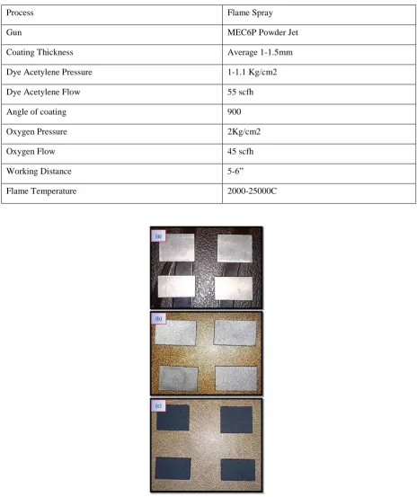
Jodhpur, India Fig. 2 with the parameters as listed in Table 3. The grit blasted and coated samples are shown in
Fig. 3.
Table 3 : Flame Spray Parameter Details
Process Flame Spray
Gun MEC6P Powder Jet
Coating Thickness Average 1-1.5mm
Dye Acetylene Pressure 1-1.1 Kg/cm2
Dye Acetylene Flow 55 scfh
Angle of coating 900
Oxygen Pressure 2Kg/cm2
Oxygen Flow 45 scfh
Working Distance 5-6”
Flame Temperature 2000-25000C
Fig. 3: substrate samples; (a) samples cut from sheet of Al. Alloy 7075, (b) grit blasted samples,
2.3CHARACTERIZATION
Particle morphology of Al2O3:TiO2 with composition 87:13 and 50:50 powders as well as coated samples were
performed by scanned electron microscopy [8] using SEM, ZEISS, SUPRA 55. The reflection loss of EM waves
was measured using Keysight E-8363C, Vector-Network-Analyzer in X-Band using WR-90 [14-15].
3.
RESULTS AND DISCUSSIONS
3.1 MORPHOLOGY
Fig. 5 shows the SEM microstructures of sample 1 and sample.
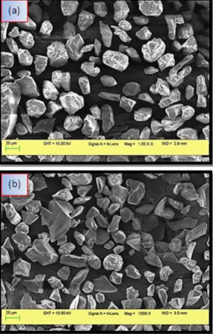
Fig. 4: powder sem images of Al2O3: TiO2 with composition (a) 87:13 and (b) 50:50
Morphologies of Al2O3:TiO2, in 87:13 and 50:50 commercially available composite powders are shown in Fig.
4, consequently first composition had morphology of dense solid particles with particle size in a range of 15–45
μm and mean particle size of 30 μm whereas the dense solid particles with particle size in a range of 15–43 μm with mean particle size of 32 μm specified by second composition.
Nanocomposite powders showed normal size distributions and presence of small particles of TiO2 on the surface
Fig. 5: sem images of coated al2o3: tio2 (a) 87:13 (b) 50:50
Fig. 4(a) revealed more TiO2 particle collection on Al2O3 as compared to Fig. 4 (b) due to less proportionate
composition of TiO2 in it. Surface morphologies of the coated samples 1 and sample 2 using flame spraying
shown the presence of agglomerate like particles indicated by Fig. 5(a) and 5(b).
Although there is no such significant differences in these two SEM images except that the composites are more
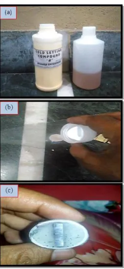
agglomerated in Sample 1 than Sample 2. To investigate the cross sectional morphology sample mounting has
been done using cold setting compound and cold resign as shown by subsequent Fig. 6(a) and 6(b) followed by
polishing of the surface with successive grade emery papers and velvet clothing using rotating wheel technique
at DAV University, Jalandhar, Fig. 6(c).The mounted samples were then exposed to scanned electron
microscope for cross sectional images of the samples as shown by Fig. 7.
Fig. 7: sem cross sectional of ceramic coated samples in ratios (a) 87:13 (b) 50:50
3.2 ELECTRICAL PROPERTIES
The microwave absorption property of material is typically characterized in terms of the power reflection of a
plane wave reflected from an metallic surface, aluminum alloy 7075 coated by ceramic by flame spraying.
The power reflection or reflectivity of the coating, [3] generally produced for normal incidence, is commonly
expressed as:
(4)
Where, Γ, Zin and Z0 present the reflection coefficient, input impedance of the coating, and intrinsic impedance
of free space with a value of 377 Ω respectively. According to the transmission theory, for a single-layer
absorber backed by a perfect conductor, the input impedance of the absorber Zin of a metal-backed microwave
absorbing coating is given:
(5)
and
η, γ, d, є and µ denote the intrinsic impedance, propagation constant, thickness, relative complex permittivity
and permeability of the composite coating respectively. c and f are the velocity of light and the frequency of
wave incident. As we know, in order to design microwave absorbing coating with a high performance, two
important conditions should be satisfied [18]. The first condition is impedance matching, which requests the
input impedance of coatings should be made approximate to the impedance of free space insuring the
microwave enters absorption coatings as much as possible. When Zin = Z0, the impedance matching is satisfied
perfectly, and EM wave will be incident completely without any reflection, theoretically. Secondly, the incident
wave should be attenuated rapidly through the material layer as far as possible.
In order to characterize the microwave absorbing properties of the composite coatings based on Al alloy
sheet, the reflection loss (RL) curves versus frequency for different compositions of ceramics oxides are shown
in Fig. 8. The composition, in weight ratios 87:13 and 50:50 has been studied. The sweeping frequency was
ranged from 8 to 12 GHz (X-Band).
Fig. 8: electrical testing for reflection loss calculation, S
11At microwave frequencies, various measurement techniques like free space measurement technique, resonant
cavity technique, transmission line technique, dielectric probe technique are available. In this work, dielectric
probe technique is used to measure S11 parameters. It includes a 50GHz Agilent network analyzer having
Agilent Technologies 85071 measurement software. Before Measurement, Calibration of VNA is required.
There are 2 steps for measurement of S parameters.
3.2.1 CALIBRATION PHASE
The process of calibration is also called as Vector Error Correction. Vector-error correction is the process of
characterizing systematic error terms by measuring known calibration standards, and then removing the effects
of these errors from subsequent measurements. Before measuring, calibration at the tip of the probe must be
performed. It corrects for the directivity, tracking, and source match errors that can be present in a reflection
measurement. The Method used for the calibration before measurement of dielectric constant is called one port
calibration method. Calibration is done with standard calibration kit provided with the VNA and originally
calibrated results are stored in a file in the VNA named as calibration kit. The empty WR 90 Waveguide is
inserted between the two port co-axial cables of VNA and then the dielectric constant of air is made to real at
3.2.2 CALCULATION PHASE
After calibration of VNA, coated samples are carefully placed under the surface of WR-90 in a manner that it
properly covers the openings of WR90. The measurement was done in the range of 8GHz – 12GHz with WR-90
wave guide.
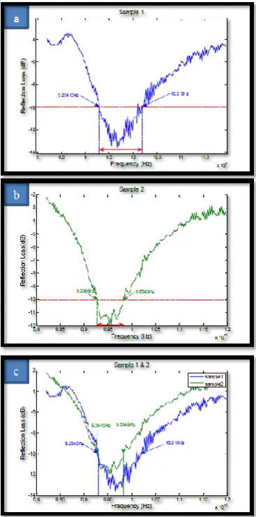
The measured S11 parameter at various frequency points in the range 8.2GHz to 12.4GHz from VNA was
plotted using MATLAB as shown in Fig. 9. It is found that the allowable reflection loss (RL ≤ −10 dB, for over
90% microwave absorption) can get in the frequency range of 9.238GHz – 10.2GHz by varying the composition
of coating composites. It is worth noting that, in Fig. 9(a), the sample 1 display good absorption properties over
>4dB in the complete X band and exhibits >90% absorption properties from 9.238GHz – 10.2GHz and extreme
reflection loss of -13.6dB at 9.683GHz. Whereas by increasing the content of TiO2 i.e. sample 2 with 50:50 %
composition of Al2O3:TiO2, <-10dB absorption was monitored from 9.28GHz to 9.82GHz with maximum
reflection loss of -11.936dB at 9.53 GHz. Hence it is experimentally being concluded that 87:13 composition of
Al2O3:TiO2 ceramics gives better absorption at broader band width than 50-50 composition as shown by S11
characteristics of both the samples plotted simultaneously in Fig. 9(c).
4.
CONCLUSION
The fabrication of Al2O3 : TiO2 ; two different compositions as 87:13 and 50:50 coatings with flame spraying
was studied and experimentally tested using VNA in X band. It was found that Flame Spraying preserves the
shape due to less temperature operation involved in the process results in production of effective radar absorbing
coatings and exihibits more than 90% absorption. It is concluded that 87:13 composition of Al2O3 : TiO2 results
in better reflection loss of -13.6dB in the frequency range 9.238GHz – 10.2GHz than 50:50 composition as it
results in maximum reflection loss of -11.936dB from 9.28GHz to 9.82GHz.
ACKNOWLEDGEMENTS
Authors wish to thank I.K.G. Punjab Technical University, Jalandhar, for providing advanced research facilities
during research work.
REFERENCES
[1] Vinoy, K.J., Jha, R.M,Radar Absorbing Materials From Theory to Design and Characterization, Springer
US , 978-1-4613-8065-8
[2] http://www.thermalspray.org/
[3] Duan Yupinga, Wu Guanglia, Gu Shuchaoa, Li Shuqinga,b, Ma Guojiab, Study on microwave absorbing
properties of carbonyl–iron composite coating based on PVC and Al sheet, Applied Surface Science 258
(2012) 5746– 5752.
[4] Chang-feng Zhang, Wen Tang, Xiao-Iong Mi, Le-ran Chen, Application of Radar Absorbing Material in
Design of Metal Space Frame Radomes, 2011 Cross Strait Quad-Regional Radio Science and Wireless
Technology Conference 222-225.
[5] Ganesan, L. J. (2013). Reduction of Electromagnetic Interference in Three Phase Squirrel Cage Induction
Motor by Coating of Nano Composite Filled Enamel to the Windings of the Motor, 978–981.
[6] Suneet Guptal , Gagan Deep, Agricultural Waste Based-Coco Peat And Coconut Shell Activated Carbon
Microwave Absorber, Proceedings of , International Microwave and RF Conference 2016,
978-1-5090-4685-0/16 ©2016 IEEE.
[7] Yang, Z., Luo, F., Zhou, W., Zhu, D., & Huang, Z. (2016). Design of a broadband electromagnetic
absorbers based on TiO2/Al2O3ceramic coatings with metamaterial surfaces. Journal of Alloys and
Compounds, 687, 384–388. https://doi.org/10.1016/j.jallcom.2016.06.166
[8] Dejang, N., Watcharapasorn, A., Wirojupatump, S., Niranatlumpong, P., & Jiansirisomboon, S. (2010).
Fabrication and properties of plasma-sprayed Al2O3/TiO2 composite coatings: A role of nano-sized
TiO2 addition. Surface and Coatings Technology, 204(9–10), 1651–1657.
[9] Merati, A. (2011). Materials Replacement for Aging Aircraft. Corrosion Fatigue and Environmentally
Assisted Cracking in Aging Military Vehicles, (Mmc), 22. Retrieved from
ftp://ftp.rta.nato.int/PubFullText/RTO/AG/RTO-AG-AVT-140///AG-AVT-140-24.pdf
[10] Lin, C. T., Swanson, B., Kolody, M., Sizemore, C., & Bahns, J. (2003). Nanograin magnetoresistive
manganite coatings for EMI shielding against directed energy pulses. Progress in Organic Coatings,
47(3–4), 190–197. https://doi.org/10.1016/S0300-9440(03)00138-3
[11] Bhattacharya, P., Sahoo, S., & Das, C. K. (2012). Microwave absorption behaviour of MWCNT based
nanocomposites in X-band region. Express Polymer Letters, 7(3), 212–223.
https://doi.org/10.3144/expresspolymlett.2013.20
[12] Duggal, S., Aul, G. D., & Chawla, V. (2017). Investigation of absorption properties of Sugarcane
Bagasse-Coal pyramidal microwave absorber. In Asia-Pacific Microwave Conference Proceedings,
APMC. https://doi.org/10.1109/APMC.2016.7931361
[13] Lisjak, D., Lintunen, P., Hujanen, A., Varis, T., Bolelli, G., Lusvarghi, L., … Drofenik, M. (2011).
Hexaferrite/polyethylene Composite coatings prepared with flame spraying. Materials Letters, 65(3),
534–536. https://doi.org/10.1016/j.matlet.2010.10.076
[14] Kaur, R., Aul, G. D., & Chawla, V. (2015). Improved reflection loss performance of dried banana leaves
pyramidal microwave absorbers by coal for application in anechoic chambers. Progress In
Electromagnetics Research M, 43.
[15] Kaur, H., Deep, G., & Chawla, V. (2015). Enhanced Reflection Loss Performance of Square Based
Pyramidal Microwave Absorber Using Rice Husk-Coal, 43(September), 165–173.
[16] Espallargas, N. (2015). Thermal Spray Coatings, 5(65), 497–509.
[17] Matikainen, V., Niemi, K., Koivuluoto, H., & Vuoristo, P. (2014). Abrasion, Erosion and Cavitation
Erosion Wear Properties of Thermally Sprayed Alumina Based Coatings. Coatings, 4(1), 18–36.
[18] Yuping, D., Guangli, W., Shuchao, G., Shuqing, L., & Guojia, M. (2012). Study on microwave absorbing
properties of carbonyl-iron composite coating based on PVC and Al sheet. Applied Surface Science,

![Fig. 1: schematic flame spray [2]](https://thumb-us.123doks.com/thumbv2/123dok_us/7780241.1284763/4.595.67.528.136.407/fig-schematic-flame-spray.webp)