System and Method for load balancing in
Unified Small Cell Router
Murugesan Nallathambi
SPVTG Business unit Cisco Systems India Private LimitedChennai, India [email protected]
Abstract—In a typical connected home or corporate network, requirement is to have a single device to terminate various inputs or single device to provide data and access service. User would like to access the various things from different device at different location. Femto and Pico cells are serving as an end point device for LTE and Video Gateway is terminating RF and serving video to the user via IP medium. Operator and user requirement is to combine both small cells and Video Gateway and make a Unified Small Cell Router (USCR) so that device maintenance and accessibility would be easier. This paper address the possible architecture of USCR and the factors need to be considered in Self Organizing Network algorithm for USCR.
Keywords—Small Cell; Self Organizing Networks; Video Gateway; Unified Small Cell Router
I. INTRODUCTION
LTE (Long Term Evolution) is a packet switched radio access technology standardized by 3rd Generation Partnership Project [4]. It supports higher data rates (up to 300 Mbps in downlink and 75 Mbps in uplink) and lower latency than other legacy systems. It supports orthogonal frequency division multiple access (OFDMA) in downlink and single carrier frequency division multiple access (SC-FDMA) in uplink [5].
Small cells are low-power wireless access points (APs) that provide improved cellular coverage for homes and enterprises as well as metropolitan and rural public spaces. These small cells are also used to reduce Qos degradation so that it improves the data throughput for mobile users. This small cell includes Pico cell which cover in the range of 200 meters and typically used in apartments and corporate office. Femto cell can cover in the order of 10 meters and typically used in home.
A. About Small Cell
When there is a large number of small cells, coverage will be improved but interference and
managing those devices will be challenging task. It becomes important to provide Self Organizing Network (SON) capabilities such as dynamic optimization in small cell networks so that it will reduce the operating cost of the operator. This SON includes self-configuring, self-optimizing the device parameters, Load balancing, finding the Neighbor and doing handover to the correct device when User Equipment (UE) moves across the region.
Load balancing is the SON algorithm by which the small cell network can share the traffic. With limitation of hardware resources and spectrum, small cell needs to take decision whether to accept
incoming handover request. Also, if neighbor is ready to share take some load then small cell have to handover some of the UEs to the neighbor.
AP to another AP. It becomes desirable to have an NCL list that helps to reduce QoS degradation upon handover. It is also needed handover decision needs to be consider the internal CPU load and hardware resource limitation.
B. About Video Gateway
Video Gateway (VGW) is a hybrid device which inputs are Radio Frequency (RF) input and IP (it can be Ethernet or cable modem). Radio frequency input can be come from different medium like satellite, terrestrial and cable which use different modulation scheme. VGW demodulate RF signal, transcode it. Output of VGW is connected to home network (which can be Wi-Fi, Multimedia Over Cable Alliance etc.,). Home networking standard like Digital Living Network Alliance (DLNA) allows UE to request content from Gateway and play it on the UE. For example,
1. UE asks for list of live channels available in RF network. VGW get the request, and check the channel list is available in its local cache. If channel list is not available, it will tune to RF channel, get the list according to [9] and store it in its local cache. The stored channel list will be send to UE via home network
2. UE asks channel number 1’s video and audio content. On getting this request, VGW tune to RF channel #1, transcode it and buffer content in its local circular buffer. The buffered content will be send to UE via local home network
VGW also terminate the service based copy protection. It decrypts the content based on operator and encrypts it for the home networking (simple encryption scheme like DTCP-IP is used in most of the time). VGW may contain big persistent storage (like hard-disk or compact flash) to store the video content which can be retried/played back after sometime.. VGW used to contain many RF tuners in order to service many clients (UE).
Most of the VGW is designed to work alone and work in home environment. When VGW is deployed in big apartments or in enterprise or in big stadium, it needs to communicate with other VGW and share the resource. Deployment of VGW and LTE small-cells are going to happen in same place and almost same purpose (as Video is the most traffic in LTE and IP world). Also, most of the video being watched in UE instead of legacy set top boxes so it is make sense to combine both VGW and small cell into a single box.
I. UNIFIED SMALL CELL ROUTER
Figure 1 Unified Small Cell Router block diagram
Figure 1 describes the block diagram of Unified Small Cell Router (USCR), it has video tuners (it can be inserted via PCI slot or via USB or Ethernet port) attached to Pico or Femto cells. This tuner card will have tuner PLL, demodulator (based on RF network) and output interface module. In addition to normal LTE operation, this USCR will be having two hardware components. One is to transcode the incoming video content and hardware is legacy LTE small cell hardware. LTE hardware receives the content - it can be video, audio or data (like channel, recorded list) from transcoding hardware and also from IP backhaul. Output of USCR is COFDM signal or MOCA to support legacy set top boxes.
II. SONALGORITHM
content from unicast URL. If this channel is
available in Evolved Broadcast Multicast Signal then UE will join into this broadcast and get the signal from EnodeB. Evolved Broadcast Multicast Signal is the standard by which video can be
broadcasted/multicast in LTE, because of bandwidth limitation, video quality in this mode of transmission may be less compare to high quality video available in RF.
Figure 2 SON Algorithm
C. Neighbor Cell List Mechanism
USCR maintains the neighbor list and each neighbor list's capabilities (it includes it has support for video tuners, how many resource available etc., ). There are lot of prior art [1] to describe how to prepare Neighbor Relation Table (NRT). Most of the NRT algorithm use A3 or A4 events from UE and by doing the self-measuring. Based on the power level of neighbor (it varies based on UE moving direction) it assigns priority to SCR and this list will be sorted based on priority. In the background, serving SCR will try to establish the X2 interface to the top few neighbors. It get various factors like number of tuners, have recording capabilities, load available etc., the cell list algorithm uses these variables and recalculate the priority. X2 is the point-to-point interface between two eNBs within the E-UTRAN. A point to-point logical interface should be feasible even in the absence of a physical direct connection between the two SCRs[3].
To address USCR requirements, we are proposing following changes in [3]
1. "Served Cell Information” in can be added with following variables
TABLES I Served cell Information Message
No table of figures entries found.
Presenc e
Rang e
IE type and referenc e
Semantics descriptio n
Numbe r of Tuner
O 1 to <max >
INTEGE R
Number of Tuners attached to the SCR. If this value zero means, then SCR doesn't support VGW functionali ty Storag
e
O 0 or 1 INTEGE R
Indicate storage supported
2. "Load Information" message is sent by an SCR to transfer load and interference co-ordination
information. Following fields can be added into this information to describe Video Gateway functionality in SCR
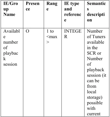
TABLE II Load Information Message
IE/Gro up Name
Presen ce
Rang e
IE type and referenc e
Semantic s descripti on
Availabl e number of playbac k session
O 1 to <max >
INTEGE R
load. If this value zero means, then SCR can't take new video playback request power
mode
O 1 to <max numb er of power mode >
INTEGE R
indicates current power mode of USCR
D. Load balancing Mechanism
USCR has two separate hardware entity, it is necessary to switch off some components when not in use. By default, all attached tuners and video hardware is powered off in USCR. At uniform time interval, USCR software wakes up and collects the Meta data from the RF path and keeps it in the local storage. It is also possible that this hardware can be wake up by the scheduled recording. This scheduled recording can be happen at local storage or storage share by many USCR (common cloud storage for the particular community or enterprise).
The load balancing algorithm mentioned in prior art [7] is,
1) Get potential Target eNBs list for Handover. 2) Sort above list based on priority of eNBs
(priority == available resource blocks and neighbor's neighbor load). Get available resource blocks via X2 and neighbor's neighbor load from server. Final list will be Target EnodeB which can accommodate many UEs are listed first
Loop:
3) Increase Handover value by one step 4) With the modified Handover offset, check
how many UEs can be handover. Check for each UE, how many resource blocks are required.
5) Take one Target cell from cell list, compare number of available resource with UE
required resource - if cell can accommodate then start HO
6) Do the step 5, till all UEs are handover or cell list exhausted with this modified Handover offset
7) Go Loop: - if still current cell is having more load
In addition the above, USCR needs to do following while handover or while accepting the incoming request.
1) USCR advertise its current resource status via Load information message
2) On accepting each video request, it decrements "Available number of playback session". It is possible that single UE can consume multiple playback session (one is watch the content and another to record) 3) When currently serving UEs are asking for
more video request (opening multiple streaming application) which USCR couldn't handle with required Qos then
a. USCR tries to terminate the old un-used session
b. Handoff the session which can be handled by other friendly neighbor. For example, recording to the common community storage can be handled by the friendly neighbor (which can be far away from serving USCR)
c. Handover UE (which are getting enough signal power from the neighbor) to the appropriate neighbor. If SCR (which support video) is available then give more priority to the UE which is using video session currently.
4) Accept UE based on its policy (some UE has the requirement to play multiple video content at the time of handover) and current resource availability.
power mode" is set to VGW deep standby in load information.
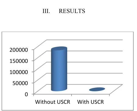
III. RESULTS
Figure 3 Analysis of bytes consumption in LTE backhaul
Figure 3 results is taken with the following parameters
Distance - 1000 meter Number of USCR-Pico cell required - 5 3 USCR has connected with 8 RF tuners - 3 * 8 = 24
2 USCR is connect with 5 RF tuners - 2 * 5 =10
So, totally 34 live video sessions can be serviced from this USCR from RF channel. So, if 34 sessions are active at a time and each serving HD channel of 12 Mbps total of 179 Giga Bytes IP traffic can be avoided
IV. CONCLUSION
We have proposed new possible product which will serve the user requirement to watch from anywhere with limited usage of IP. In this way, we are proposing to use RF channel when it is available. This will reduce the LTE backhaul traffic and server load. We have also proposed method to do load balancing and communicate the load information related to video hardware. This product would be beneficial to the operator who is running both RF channel and LTE network.
V. REFERENCES
[1] Yoshinori Watanabe, Yasuhiko Matsunaga, Kosei Kobayashi, Hiroto Sugahara, and Kojiro Hamabe, “Dynamic Neighbor Cell List Management for Handover Optimization in LTE,” IEEE Vehicular Technology Conference (VTC Spring), 2011 IEEE 73rd.
[2] 3GPP TS 36.300 “LTE; Evolved Universal Terrestrial Radio Access (E-UTRA) and Evolved Universal Terrestrial Radio Access Network (E-UTRAN); Overall Description;Stage 2”
[3] 3GPP TS 36.423 “Evolved Universal Terrestrial Radio Access Network (E-UTRAN); X2 application protocol (X2AP)”
[4] 3GPP specifications, www.3gpp.org
[5] H. Holma and A. Toskala, “LTE for UMTS – OFDMA and SC-FDMA based Radio Access,” John Wiley & Sons Ltd., 2009
[6] Small Cell Forum, www.smallcellforum.org
[7] Andreas Lobinger (NSN), Szymon Stefanski (NSN), Thomas Jansen (TUBS) and Irina Balan (IBBT), "Load Balancing in Downlink LTE Self-Optimizing Networks". http://www.fp7-socrates.org/files/Presentations/SOCRATES_20 10_VTCSpring%20%20LB%20presentation.pdf
[8] Mukesh Taneja, Vikas Bangalore, Gajanana Garuda, Murugesan Nallathambi, Shishir Gupta, Policy based Automatic Neighbor Relation Management for small cell Networks
[9] Digital video broadcasting specification for Service information(SI) in DVB systems -
http://www.etsi.org/deliver/etsi_en/300400_3004 99/300468/01.11.01_60/en_300468v011101.pdf 0
50000 100000 150000 200000