Modelling and validation of dynamic parameters
and material heterogeneous damping properties
of foundation structures and subsoils
Michail Voskresenskiy1, Victor Mikhaylov2,*, and Oleg Pakhmurin3
1PhD, Institute of Geophysics UB of RAS, Yekaterinburg, Russia
2Head of SCAD SOFT scientific and technical support centre, MSc, 630132 Novosibirsk, Russia 3Prof. TSUAB, PhD in Engineering Science, 634003 Tomsk, Russia
Abstract.In this paper, an integrated technology for performing finite element calculations in SCAD Office FEA-software with instrumental verification of actual dynamic characteristics of load-bearing structures and subsoils with the use of seismic hardware-software complex REGISTR is proposed.
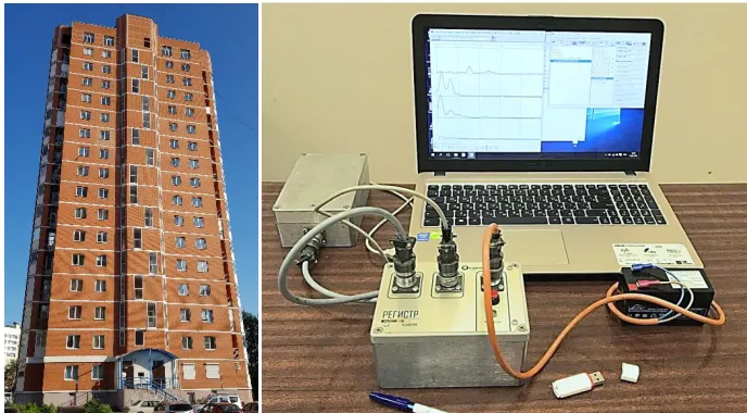
The investigated multi-story residential building with precast-monolithic reinforced concrete frame (Fig. 1) was described in one of the reports prepared under the guidance of Oleg Pakhmurin [1]. The authors express their sincere gratitude for the provided design task, the solution of which made it possible to demonstrate the technology of seismic signal recorder REGISTR usage together with the SCAD Office FEA-Software according to design guide SP 26.13330.2012 “Foundations of machines with dynamic loads”.
Fig. 1. Analysed multi-storey residential building and tree component seismic complex REGISTR
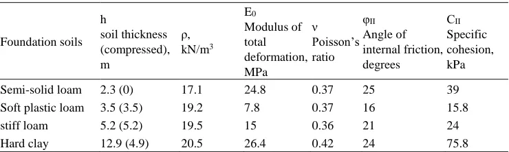
The engineering and geological description of the soil ground base of the investigated building is shown in Table 1. The calculation of the dynamic characteristics of the subsoil according to SP 26.13330.2012 is given in the second Table 2. Relative damping is converted to equivalent one in accordance with ASCE 4-16 “Seismic Analysis of Safety-Related Nuclear Structures” due to the convenience of entering data into the interface of SCAD [2].
Table 1. Subsoil parameters
Foundation soils h soil thickness (compressed), m ρ, kN/m3 E0 Modulus of total deformation, MPa ν Poisson’s ratio φII Angle of internal friction, degrees СII Specific cohesion, kPa
Semi-solid loam 2.3 (0) 17.1 24.8 0.37 25 39
Soft plastic loam 3.5 (3.5) 19.2 7.8 0.37 16 15.8
stiff loam 5.2 (5.2) 19.5 15 0.36 21 24
Hard clay 12.9 (4.9) 20.5 26.4 0.42 24 75.8
Table 2. Design Code SP 26.13330.2012 parameters for soil-structure interaction analysis of shallow foundation
Ground base motions Stiffness parameters k Damping parameters c
Vertical, Z kz=CzA
=13100 MN/m
(
2
)
(
2
)
c
=
c
z cr
zk
zm
p
= 331 MN∙sec/mHorizontal, X (Y)
k
x/y=
C
x/y
A
=9200 MN/m
c
z0.6
=
c
x/y 198 MN∙sec/mRotary in vertical plane kx/y=Cx/yIx/y
=560 / 2310 x 103 MN∙m
c
x/y=
0.5
c
z
165 MN∙m∙secTorsional in horizontal plane (around Z)
t t t =C I
k
= 1120 x 103 MN∙m
c
t=
0.3
c
z
99 MN∙m∙sec Where ) / 1 ( b =Cz 0E A10 A =25.3MN/m
3 – bedding ratio of elastic uniform compression, where b0 – coefficient assumed equal 1 for sandy soil, 1.2 for clayey sand and loam soil, and 1.5 for clay and macro fragmental soil; E=E0=17,2 MPa– modulus of total deformation of the soil under foundation slab (for nonhomogeneous subsoil E is the average modulus within the compressible mass h0=13.6 m); А10=10 m2; А=520 м2 area of designed foundation slab(For slabs ≥200 м2С
z will be as for the
slab with the area А=200 м2); Сψ
x/ψy=2∙Сz – bedding ration of elastic non-uniform rotation;
Сx/y=0.7∙Сz – bedding ratio of elastic uniform shear; Сt=Сz – bedding ratio of elastic non-uniform
tortion; Iψx/ψy=bh3/12=11.1∙103/45.8∙103, It≈b3h/3=44.4∙103m4– respectively, moments of inertia of
the foundation slab (footing size b∙h=32.5∙16 m) relative to the horizontal axes which is perpendicular to the vibration plane, and to the relative to the vertical axis (all the orthogonal axes pass through the foundation slab center of gravity); ccr2 kzm– critical coefficient of viscous damping at which
soil-structure behavior starts to lose its oscillatory response (it enables a transition from relative damping in fractions of critical ξz=cz/ccr according to Design Code SP 26.13330 to viscous equivalent
damping cz=ξz/ccr according to Design Code ASCE 4-16 [3]);
z
2
p
- relative damping forFigure 2 shows the amplitude spectra of the distribution of natural frequencies in three orthogonal directions processed in the specialized software Reg3MSD (Certificate No. 2016618341. Registered in the Computer Program Register on July 27, 2016). The REGISTR software and hardware system for measuring and analysing seismic data was developed at the Institute of Geophysics, Ural Branch of the Russian Academy of Sciences by T.E. Senina, L.N. Senin and M.N. Voskresenskiy [4].
On the graph along the abscissa axis the frequencies in Hz are indicated. On the ordinate axis - conventional units of the discharge grid from 0 to 100% of the maximum specific value of the spectrum in each of the directions. The green colour indicates the frequencies of a load-free subsoil at a distance of 20 m from the building with a maximum specific value of 100%. The red colour indicates the frequencies in the centre of the foundation slab with a maximum specific value of 50%, halved for ease of display and comparative analysis of two measurements. The solid lines indicate the frequencies for vertical vibrations along the Z axis, the dashed lines indicate horizontal ones along the X axis, and dotted lines indicate the Y axis. Thin black arrows indicate the dominant frequencies for the measurement point on a ground surface free from building load. Thick black arrows are the dominant frequencies for the point in the centre of the foundation slab with the load from the building.
Fig. 2. Instrumental amplitude-frequency spectra of seismograms of the investigated building from 1 to 30 Hz and points with calculated values of natural frequencies of an equivalent subsoil according to formula (1) and SP 26.13330.2012
Soil dominant frequencies under the rigid structure for vertical ground base motions along Z axes and for horizontal ones могут can be determined by the following formula:
m
k
f
z x y z x y/ / /
/
2
1
(1)In the preliminary assessment of the natural frequencies according to formula (1), the assumption about the similarity of the structure’s vibrations on an elastic weightless base and the simplest single-mass oscillator is used. In the provisions of SP 26.13330.2012, the mass of the structure with the foundation and the weight of the soil on the cantilever overhangs of the foundation slab are taken as the mass of the oscillator m. The mass of the subsoil involved in the vibrations together with the foundation slab is not taken into account.
1 2 3 4 5 6 7 8 9 10 11 12 13 14 15 16 17 18 19 20 21 22 23 24 25 26 27 28 29 30
Z1 Fz1* Z2 Fz2*
X1 Fx1* X2 Fx2*
Y1 Fy1* Y2 Fy2*
In the methodology of Japanese authors [5], when assessing the presence of the inverse effect of building vibrations on the ground base vibrations, there is a parameter of the relative mass of the structure in the form of a ratio to the attached mass of the subsoil. The
mass of subsoil involved
m
soil is represented as the product of the equivalent radius of thefoundation slab area 𝑟 = √𝐴/π in a cubic degree and the averaged density of soils ρ below under the foundation to a depth of r:
2 3
A
m
soil (2)In Fig. 2 additional dots of green colour correspond to the calculated natural frequencies of the subsoil, free of load, with stiffness according to formula (1) and the soil attached mass according to formula (2). The red dots show the natural frequencies of the structure as a rigid body on a massless subsoil. For all points, the equivalent stiffness
k
z/x/y wascalculated according to SP 26.13330.2012. Round dots indicate the frequencies of oscillations in the horizontal direction, diamond-shaped points indicate the frequencies of vertical vibrations.
Small points refer to the calculation of equivalent stiffness in strict accordance with clause 6.1.2. of SP 26.13330 on the basis of the total deformation modulus E0, as in standard geological surveys, taking into account plastic deformations from normative long-term loads.
Larger points refer to natural frequencies for equivalent stiffnesses, also calculated in accordance with clause 6.1.2 of SP 26.13330.2012, but based on the dynamic modulus of elastic deformation Ee, determined depending on the propagation velocity of seismic waves by geophysical methods. In the absence of engineering-geological or geophysical survey data, it is allowed to take Ee five times higher than the total deformation modulus E0 according to clause 5.6.31 of SP 20.13330.2016 “Foundations of buildings and structures” or ten times according to the Kazakhstan Design Code SP RK 2.03.30.2017 “Construction in seismic areas”. The previous version of Russian Design Code SP 14.13330.2011 “Construction in seismic areas” included an enlarged coefficient of conversion of the total deformation modulus to elastic dynamic deformation modulus equal to eight with the assumption that it can be determined by geophysical methods. However, this item was subsequently excluded due to the fact that for different types of soils, the dynamic modulus of elasticity and the total modulus of deformations can differ from 4 to 14 times or more. Therefore, it can only be determined in the course of geological or geophysical surveys. In this study, a conversion coefficient of Ee=10 E0 is adopted for the larger points. As the second stage of scientific study, the authors plan to use the 24-channel SINUS seismic station for investigation of the upper part of the geological section. This will determine the actual wave propagation velocity in a layered subsoil, including the dynamic modulus of elasticity Ee [6].
On the one hand, when examining objects, usually more pronounced peaks are obtained that are not observed within the current building under study. This may be due to the presence of weak bulk soils below the foundation slab. In addition, to clarify these characteristics, it is necessary to carry out repeated measurements at night time with minimizing the level of white noise interference, which was not done. On the other hand, all natural frequencies calculated according to SP 26.13330.2012 using the common deformation modulus E0 are in the vicinity of the first peak points in the frequency spectra, but significantly differ from the maximum dominant frequencies. This indicates that before starting the research, it is first necessary to determine the preliminary expected frequencies by engineering methods and the finite element method. To clarify and adjust the data, it is necessary to carry out additional measurements at night, when the anthropogenic impact is minimal. Then, in the process of final processing of the results, it is necessary to analyse the spectra not for all measured frequencies, but only in the vicinity of the observed resonant frequencies in order to exclude the overlap of the second and higher harmonics of natural frequencies. It should be noted that the methodology laid down in the REGISTR software-instrumental complex does not require additional induced loads from a vibration machine.
One of the most difficult aspects of performing dynamic calculations of building structures is the consideration of the damping properties of materials. Unlike mechanical engineering tasks, building materials and soils possess not only significantly greater variability of properties and initial imperfections, but also often enough within one task they require simultaneous consideration of inhomogeneous damping in structures made of different materials and in layered subsoil. Therefore, as a separate stage of the instrumental assessment of the dynamic parameters of the structure and of the subsoil, the logarithmic attenuation decrement is determined for the dominant frequencies.
At point No. 1 of the free ground base for the vertical component Z at a dominant frequency fZ1=9.7 Hz, the attenuation decrement was δZ1=0.69. For horizontal directions along X (N-S) and Y (E-W) at the corresponding dominant frequencies fX1=9.1 Hz and fY1=9.3 Hz, the values of the logarithmic attenuation decrement are δX1=0.81 and δY1=1.02. Thus, the average horizontal attenuation decrement is δH1=0.92. At the same time, at point No. 2 in the centre of the foundation slab at a vertical dominant frequency fZ2=11.3 Hz, the attenuation decrement was δZ2=0.83. At horizontal dominant frequencies fX1=9.4 Hz and fY1=9.2 Hz, the average attenuation decrement is δH2=0.81.
Figure 3 shows the relative damping parameters in fractions of the critical, calculated according to SP 26.13330.2012 and instrumentally measured. For the convenience of performing a comparative analysis, the equivalent damping values given in Table 2, previously transformed to the ASCE 4-16 form, were inverted to the relative fraction of the critical ξz=cz/ccr. According to the SP methodology 26.13330.2012, relative damping can be calculated by formula (14) as for unstable (impulse) dynamic actions for vertical ξZ1 and horizontal ξH1 directions. However, the instrumental measurements are closer to the damping values from stable harmonic or random dynamic influences regulated by formula (13) in SP 26.13330.2012. These relative damping values are indicated in Fig. 3 as ξZ2 and ξH2.
Instrumentally fixed damping parameters of the subsoil in the form of a logarithmic damping decrement can be converted into relative damping using the following formula:
2 22
(3)If it is necessary to transfer the damping parameters of the structure from random vibration effects determined from the measurement data to damping under significant impulse or seismic effects, the coefficient of the ratio of damping under impulse actions according to formula 13 of SP 26.13330.2012 to damping under random vibrations according to formula 14 (description of the parameters is given in Table 2):
p
p
C
E
K
imp Z2
6
(4)For the considered building, the coefficient of transition of relative damping with weak random dynamic effects to relative damping with significant impulses Kimp=ξZ1/ξZ2=2.47.
Fig. 3. The relative damping parameters calculated in accordance with SP 26.13330.2012 (1 and 2) and instrumentally measured (3 and 4) in fractions of the critical for vertical (Z) and horizontal (H) vibrations under impulse (1) and random (2) dynamic effects.
The results of instrumental estimation of the relative damping parameters in the building structures and its foundation obtained using the three-component seismic registrar REGISTER allow us to switch to an accurate model for performing finite element calculations in the SCAD interface.
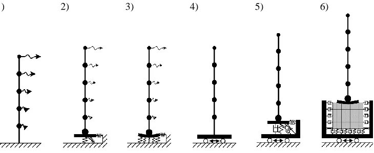
When performing linear dynamic calculations of load-bearing structures, two main methods, fully implemented in SCAD Office, are widely used. The simplest and most common is the quasistatic method of calculation based on modal analysis, in which there are individual static moments in time, when the dynamic external influence coincides with one of the natural periods of oscillation. In Figure 4, this main method may include three approaches to creating models: 1) a compliant structure on a rigid foundation; 2) a compliant structure with equivalent constraints of finite rigidity in the centre of an absolutely rigid foundation slab, used in SP 26.13330; 3) a compliant structure on a foundation slab or pile raft with distributed bedding coefficients. Based on the modal analysis, additional calculations of the amplitude-frequency characteristics and response spectra of the structures in the frequency range are available in SCAD Office.
The second method of calculation is the direct integration of the equations of motion in time. On the one hand, using the same foundation modelling approaches (Schemes 1-3, Fig. 4), a time-varying loads can be applied in each node of the design model, which in construction tasks can be represented by aerodynamic processes or moving loads, but it is enough difficult in the mathematical description of the effects.
0,425
0,255
0,172
0,103
0,128 0,109
0,131 0,108
0 0,1 0,2 0,3 0,4 0,5ξz.1
ξh.1
ξz.2
ξh.2
ξz.3 ξh.3
The most common and significant for ensuring the technical safety of the bearing structures are tectonic seismic impacts regulated by SP 14.13330, as well as industrial dynamic and technogenic seismic impacts regulated by the new Design Code SP 413.1325800.2018 “Buildings and structures subject to dynamic impacts”. These seismic and industrial dynamic effects are also conveniently modelled using the integration of equations of motion in time. The last three schemes in Figure 4 describe three kinematic methods: 4) the motion of a rigid ground base relative to a compliant structure; 5) the motion of the rigid platform relative to a homogeneous subsoil in the form of equivalent springs of finite stiffness and nodal vicious dampers in the centre of an absolutely rigid foundation slab of a compliant structure; 6) the motion of an absolutely rigid platform relative to a heterogeneous finite element mass of random soil layers under a compliant structure on a foundation slab or pile raft of finite stiffness.
1) 2) 3) 4) 5) 6)
Fig. 4. Types of Soil-Structure Interaction models in SCAD Office FEA-software
In the absence of damping, with a small integration step in time and with full consideration of the modes of natural vibrations, all the above methods give almost identical results for simple systems on an absolutely rigid soil foundation. However, each of the methods has advantages and disadvantages.
As a rule, for homogeneous material design models of structures, the results of modal analysis are performed with uniform modal damping coefficients, which are assigned using table values according to design codes or generally accepted engineering design guides. In a comparative analysis, the exact solutions obtained in the frequency range reveal a certain error in the modal approach, which can be ignored with a small relative damping below 5%. This error in complex continuum systems and at a higher level of damping is due to the fact that the dynamic reaction can be associated not only with critical modal reactions in the main vibration modes, but also in lower vibration modes, which are supercritical or subcritical, which in numerical methods could be calculated with errors.
sometimes leads to an “abnormal” decrease of seismic reactions. This is explained by the dependence of reactions with the frequency composition of the action relative to the natural frequencies of the system. The “anomalousness” of the decrease in seismic reactions can be revealed by a variational comparison of several response spectra for different given damping values, instead of choosing one specific spectrum, as is usually done [7]. Thus, for structures homogeneous in material on an absolutely rigid soil foundation, the modal method has the advantage of simplicity and high speed of calculation. The advantage of direct dynamic calculation with the Rayleigh dissipation matrix is the ability to take into account the inhomogeneity of the attenuation of subsoil vibrations, by modelling it using finite elements of viscous dampers.
In the SCAD Office FEA-software, in the mode of direct integration of motion equations in time, the formulation of the system oscillation problem in absolute coordinates allows us to naturally formulate the equations for both synchronous and asynchronous excitation of constraints for any technogenic seismic impact [8]. To take into account the possibility of inhomogeneous material damping in various types of structures as part of a single design model, starting with version 21.1.7.1, a fundamentally new approach is used that does not require the fulfilment of the idealized Rayleigh mathematical hypothesis. The Rayleigh proportionality coefficients α and β for the mass and stiffness matrices do not have physical meaning and should be calculated only for two dominant frequencies responsible for damping in the lower and upper modes, respectively, using linear interpolation for damping values at other frequencies of the structure:
.
K
M
C
(5)In the new implementation of the problem, Fialko S. Yu. suggested that the dissipation matrix C should be presented in the form of damping according to the type of material, regardless of the vibration frequencies of the structure, which greatly simplifies the use of direct dynamics methods to solve standard engineering problems:
,
e e T e e
e
P
K
P
C
(6)
where γe is the inelastic resistance coefficient of the material, Ke is the stiffness matrix of element e, and Pe is the permutation matrix.
As a result, in the direct integration mode of the equations of motion, the damping can be set unique for each material assigned to the finite elements in the dialog box when describing the stiffness properties. This opens up the possibility of creating direct physical models of foundations and structures with various properties of soils and structures.
In conclusion, it should be noted that in order to perform accurate dynamic calculations of buildings and structures, taking into account the deformable subsoil, which affects the fluctuations of the entire system, it is necessary to verify the numerical models instrumentally at a similar object or after construction completion of designed structure. Using the three-channel seismic registrar REGISTER is a simple procedure and allows one to check the correctness of the natural frequencies and damping parameters determination if all the necessary geological surveys are performed and the modulus of elastic dynamic deformations is determined. If only standard engineering and geological surveys are available, additional geophysical studies are required using multichannel seismic stations, such as SINUS from the Institute of Geophysics UB of RAS, with 24 one-component geophones.
References
vibration modes of reinforced concrete frame buildings on elastic subsoil (XXVI Conference NMSPTEP, Tomsk, 2019) (to be published)
2. L.V. Nuzhdin, V.S. Mikhailov, I.D. Yankovskaya, On criterion for considering SSI effects, 210 (GFAC, St. Petersburg, 2019)
3. A.N. Birbraer, Calculation of structures for seismic resistance, 255 (1998)
4. L.N. Senin, T.E. Senina, M.N. Voskresenskiy, Hardware and software complex “REGISTR-SD” for the study of structural seismic characteristics under the exposure of elastic oscillations, Exp. Instr. and techn., 157, 4 (2017)
5. Y. Osava, Y. Kitagava, Y. Irie, Evaluation of Various Parameters on Response Analysis of Earthquake Motions Including SSI, 116 (IV Int. Conf. on Earthq. Eng., 1984)
6. L.N. Senin, T.E. Senina, M.N. Voskresenskiy, G.I. Parygin, Complex seismic investigations of upper part of geological section, Ur. Geoph. Bull., 41, 34, (2018)
7. A.G. Tyapin, Damping in direct and modal methods, Earthq. eng., 29, 4 (2012) 8. S.Yu. Fialko, Time history analysis formulation in SCAD FEA software, J. of