Performance Optimization of Pi Controller in
Three Phase Shunt Hybrid Filter Using PSO
A.Selvanayakam
1, K.Sairanjith
2, A.C.Varishnee
3, J.Priyadharshini
4Assistant Professor, Dept. of EEE, Sri Krishna College of Engineering & Technology, Coimbatore, Tamilnadu, India1
PG Student [PED], Dept. of EEE, Sri Krishna College of Engineering & Technology, Coimbatore,
Tamilnadu, India 2,3,4
ABSTRACT : This paper attempts to tune the PI parameters in the implementation on shunt hybrid filterby using ameta heuristic optimising technique like PSO.Total Harmonic Distortion is taken as the objective parameters for the reduction of THD to be reduced. The PI tuning is done using using both Zeiglers method and PSO is carried out and compared for the optimized THD value for a Shunt Hybrid filter.Zeigler method is basically a traditional method of PI tuning and PSO is an optimization method that would increase the accuracy in tuning. The optimization method used proved to be a better method in the optimization of the PI parameters for the reduction of THD. This paper has also attempted in linking PI value for the THD reduction problem.simulation is carried out based on MATALB and the results are carried out and compared for the THD and voltage ripple.
KEYWORDS : Shunt Hybrid Filter, Particle Swarm Optimization,Total Harmonic Distortion.
I.INTRODUCTION
execution time and the error tolerance obtained after the iterations.Matlab based simulation is carried out and results are tabulated and compared.
II. SHUNT HYBRID FILTER TOPOLOGY
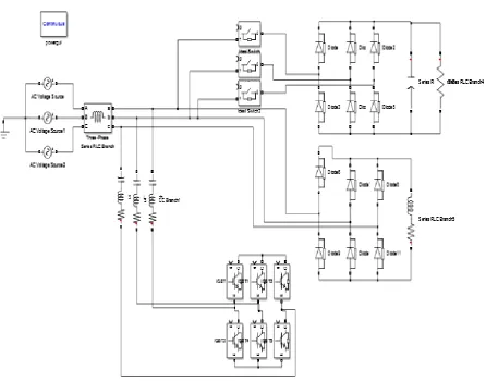
The three phase shunt hybrid filter is connected in between the source and the non linear load which is three phase diode rectifier. The hybrid flter acts as controlled current source connected in parallel with nonlinear load. It consists of a full bridge voltage source Pulse Width Modulation (PWM) inverter,high frequency in ductors and DC side capacitors that are required to shape the compensator currents.
Fig 1 : Basic circuit of Shunt Hybrid Filter
III. APPROACHES WITH ZEIGLER NICHOLS METHOD, PSO
ZEIGLER NICHOLS METHOD
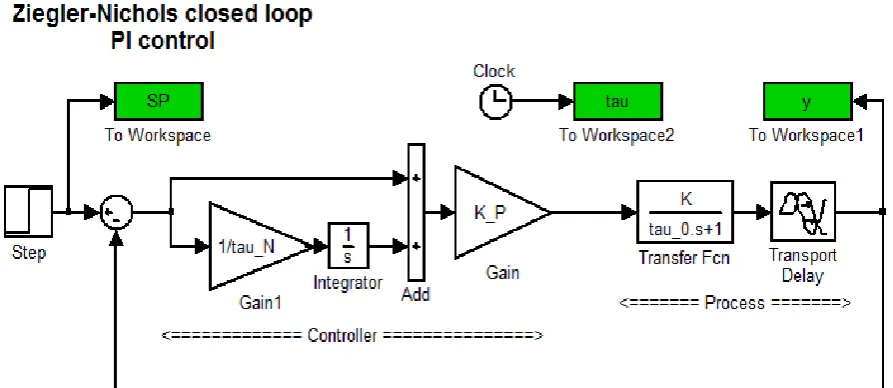
The Zeigler Nichols tuning method is a heuristic method of tuning the PI controller.Its basically performed by setting the integral value and derivative gains to zero. The proportional gain is then increased from zero until it reaches the ultimate gain,at which the output of the control loop oscillates with constant amplitude. For tuning processes that cannot run in open-loop systems as Zeigler-Nichlos closed-loop tuning method is limited. Determining the definitive gain valve is accomplished by finding the value of the proportional only gain that causes the control loop to oscillate indefinitely at steady state.This states that the gains from the Intergral and Derivative controller are set to zero so that the influence of P can be determined. Another important value associated with this proportional only control tuning method is the ultimate period. The ultimate period is the time required to complete one full oscillation while the system is at steady state. These two parameters, ultimate gain value and ultimate period of oscillation, are used to find the loop-tuning constants of the PI controller. Having the ultimate gain and frequency (ku and Pu) and using Table1, the controller parameters can be obtained.
Controller Kc I D
P 0.5Kcu - -
PI 0.45Kcu Pu/1.2 -
PID 0.6Kcu Pu/2 Pu/8
Table 1-Controller parameters for closed loop Ziegler-Nichols method
The tuning rules works well when there is an analog controller,a system that is linear, monastic and sluggish and a response that is dominated by a single pole exponential “lag” or something that acts a lot like one.
Fig2:ZEIGLER-NICHOLS CLOSED LOOP OF PI CONTROLLER
PARTICLE SWARM OPTIMIZATION
“bird” in the search space described as “particle”. In common all particles have their fitness values which are evaluated by the fitness function to be optimized and have velocities ehich direct the flying of the particles. PSO is initialized with a group of random particles that are then searched for optima by updating generations.. There are a number of iterations that occur, in each iteration every particle is updated by following two “best” values. On considering the first iteration the first one is the best solution(fitness) it has achieved so far. This value is called Pbest. Another “best” value that is tracked by the particle swarm optimizer is the best
value,obtained so far by any particle in the population. This best value is a global best and called gbest. The ith particle is represented
as Xi=(Xi1,Xi2,….,Xid) in the d-dimensional space.
Fig 3 : Concept of modification of a searching point by PSO
IV. RESULT AND DISCUSSION
The problem of harmonic reduction has been analyzed. PI tuning using both Ziegler’s method and Particle Swarm Optimization method is carried out and compared for the optimized THD value for a Shunt Hybrid filter. The obtained results show that the harmonic current control is very important. The three phase shunt hybrid filter for the three phase circuit is simulated and the Total Harmonic Distortion measure verifies the reduction of harmonics to a very low level, when the Particle Swarm Optimization method is employed. The three phase Shunt Hybrid filter provides advantages such as improvement of supply current waveform, less harmonic distortion and its use in high power/ medium voltage with the lower maximum device rating.
Simulation Results
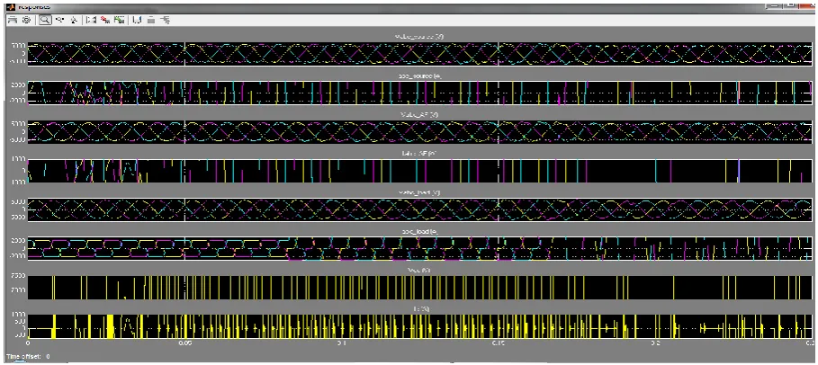
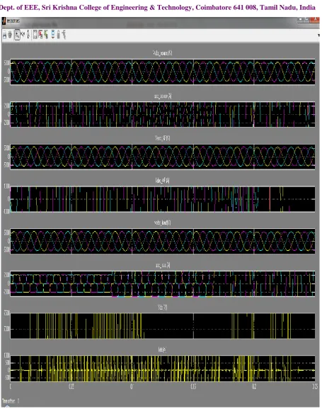
Fig 4: Waveform of Zeigler Nicholas Method
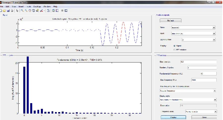
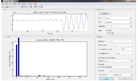
Fig 5: The THD content in the source voltage. The THD in source voltage is 7.56% in Ziegler Nichols method.
Fig 8: The THD content in voltcage source. The THD voltage source is 2.48% using PSO (Particle Swarm Optimization) method.
TOTAL HARMONIC DISTORTION RESULTS
METHODS USED VOLTAGE THD CURRENT THD
ZN METHOD 7.56 % 6.61 %
PSO METHOD 2.48 % 1.15 %
In Ziegler’s Nichols method the Total Harmonic Distortion value is 6.61% for LOAD CURRENT by using Particle Swarm Optimization method the Total Harmonic Distortion value has been comparatively reduced to 1.15% for LOAD CURRENT. In Ziegler’s Nichols method the Total Harmonic Distortion value is 7.56% for SOURCE VOLTAGE by using Particle Swarm Optimization method the Total Harmonic Distortion value has been comparatively reduced to 2.48% for SOURCE VOLTAGE.Harmonics degrades theperformance of power system. The harmonics flowing in the distribution network downgrade the quality of the electrical power supply. There can have several negative effects on the operation of the power system. Increased losses on the distribution system due to increase in the effective rms current. Over-load in neutral conductors due to cumulative increase in the third harmonics created by the single phase loads. Overloadsvibration and premature ageing of the generators, transformers and motors as well as increase in the noise level. Overloads and premature ageing of the power factor correction capacitors. Distortion of the supply voltage that can disturb the operation of the sensitive loads.Disturbances in the communication networks and telephone lines.Resonance between the supply inductance and capacitance of the power factor correction capacitors.The above disadvantages can be eliminated by reducing the harmonics in the distribution system.
REFERENCES
[1] B. Singh, K. Al-Haddad, and A. Chandra, “A review of active power filters for power quality improvements,” IEEE Trans. Ind. Electron., vol. 46, no. 5, pp. 960–971, Oct. 1999.
[2] S. Bhattacharya, T. M. Frank, D. M. Divan, and B. Banerjee, “Active filter system implementation,” IEEE Ind. Appl. Mag., vol. 4, no. 5, pp. 47– 63, Sep./Oct. 1998.
[3] H. Akagi, Y. Kanazawa, and A. Nabae, “Instantaneous reactive power compensators comprising switching devices without energy storage components,” IEEE Trans. Ind. Appl., vol. IA-20, no. 3, pp. 625–630, May 1984.
[4] F. Z. Peng, G.W. Ott, Jr., and D. J. Adams, “Harmonic and reactive power compensation based on the generalized instantaneous reactive power theory for three phase four wire system,” IEEE Trans. Power Electron., vol. 13, no. 6, pp. 1174 1181, Nov. 1998.
[5] R. S. Herrera and P. Salmeron, “Instantaneous reactive power theory: A reference in the nonlinear loads compensation,” IEEE Trans. Ind. Electron., vol. 56, no. 6, pp. 2015–2022, Jun. 2009.
[6] H. Karimi, M. Karimi-Ghartemani, and M. R. Iravani, “An adaptive filter for synchronous extraction of harmonics and distortions,” IEEE Trans. Power Del., vol. 18, no. 4, pp. 1350 1356, Oct. 2003.
[7] M. Forghani and S. Afsharnia, “Online wavelet transform based control strategy for UPQC control system,” IEEE Trans. Power Del., vol. 22, no. 1, pp. 481–491, Jan. 2007.
[8] A. Bhattacharya, C. Chakraborty, and S. Bhattacharya, “Current compensation in shunt type active power filters,” IEEE Ind. Electron. Mag., vol. 3, no. 3, pp. 38– 49, Sep. 2009.
[9] A. Hamadi, S. Rahmani, and K. Al-Haddad, “A hybrid passive filter configuration for VAR control and harmonic compensation,” IEEE Trans. Ind. Electron., vol. 57, no. 7, pp. 2419–2434, Jul. 2010.
BIOGRAPHY
SAIRANJITH.K has obtained his Bachelor’s degree in Electrical and Electronics Engineering from Dr Mahalingam College of Engineering and Technology and currently pursuing his Master’s degree in Power Electronics and Drives from Sri Krishna College of Engineering and Technology.