Eye Controlled Robotic Motion Using Video
Tracking In Real Time
Kriti Bhattacharjee 1, Dr. Manoj Soni 2
P.G. Student, Department of Mechanical and Automation Engineering, IGDTUW, New Delhi, India1 Associate Professor, Department of Mechanical and Automation Engineering, IGDTUW, New Delhi, India2
ABSTRACT: With the view of improvising human control over robots and other automated machines, a number of techniques have been devised. The aim is to make these machines more and more human friendly. This has led to technologies, which allow us to simply talk to the robot or make them follow a particular gesture instead of writing extensive codes in difficult computer languages. One such technology, which has a vast scope and thus gaining popularity, is the Eye Gaze Tracking technique. It involves communicating with the robot through the user’s eye by making it follow the eye movement.
In this paper a self-made Video Camera based Gaze tracking system has been discussed, whose output can be used to control an in house 3R robot manipulator via Arduino Uno micro controller. The process involves image acquisition using a USB web cam mounted on the user’s PC at a fixed position. The image frames obtained from video in real time undergo processing in MATLAB to provide necessary information regarding user’s point of gaze. This information can then be used to control the movement of the 3R robot using a suitable GUI in real time. In order to determine the point of gaze, firstly the face of the user is detected from the image frame. Then the eye region is cropped from the face, discarding the remaining image. From this eye region, iris and pupil are located and their centers are calculated in real time to be stored in an array. A database is thus created using multiple trial runs which forms the training data set. This database is then utilized for mapping of iris/pupil center co-ordinates to corresponding gaze points on the computer screen. Mapping is done using Euclidean distance calculated between the test data and the training set. Thus a particular set of pupil center co-ordinates correspond to a particular point on screen. This method can be used to move the cursor to a desired location on the screen using just the eye motion. The cursor is made to move on a GUI with push buttons consisting of control instructions for the 3R robot.
KEYWORDS:Video Camera based Gaze Tracking system, 3R robot control, MATLAB image processing, Real time robot control, Face detection, Iris/pupil center calculation, MATLAB-Arduino interfacing
I. INTRODUCTION
a robot that gets water for the patient when indicated, an eye controlled television, etc.), its application can also be extended to industries where gaze tracking can be used for the development of a multi modal Human-Robot interface.
II. LITERATURESURVEY
Earliest accounts of studies done on eye tracking can be traced back to 1879 when a French ophthalmologist named Louis Émile Javal noted that while reading, the readers’ eyes do not glide smoothly through the text, but instead make swift movements combined with short halts (fixations) [1]. He coined the term “saccades” to define these swift movements however he did not measure these movements. His studies were based on naked-eye observations in the absence of a more advanced technology.
Ewald Hering and M. Lamare individually measured the saccades during reading with their own individual setup but using similar techniques. In 1879, Hering wrote an article about his studies on afterimage and sounding in which He fixed a rubber tube to a cigar holder and paid attention to the sounds produced when this device was placed on both open and closed eyelids. He was able to conclude that the sounds were associated with eye movements by noting that every clapping sound corresponded to an afterimage displacement.
In 1908, Edmund Huey [2] made a device that was capable of tracking movements of the eyes while a person is reading. This primitive and quite intrusive eye tracker consisted of a special contact lens which had a small opening at the pupil. This lens was connected to an aluminum pointer which detected the changes in eye movement. Huey published his discoveries in the book “The Psychology and Pedagogy of Reading.” The first reflective non-intrusive trackers which involved reflecting light beams on the eye and filming the reflected light were built in Chicago by Guy Thomas Buswell [3]. He also observed that the rate of recognition grows, i.e the span width of recognition of necessary information in a given text increases as reading habits become mature with time.
Alfred Lukyanovich Yarbus was a psychologist who conducted studies on eye tracking and concluded that the reader’s fixation and saccades are directly associated with their interests as well as the given task. In his book “Eye Movements and Vision” [4] published in 1967, he explained that if the reader is given a set of images and then asked several questions, his gaze would focus only on those points in the images that are relevant to the asked questions. Since early 1980’s efforts have been made to develop eye tracking system for the purpose of human-computer interaction. Earlier, devices such as Electro Oculogram were developed for electric potential measurements. These devices were based on the principle that electrodes placed around the eye can detect small changes in the electric potential field during eye movements. Later on, non contact eye tracking methods were developed based on Video camera and image processing techniques.
In order to track the eyes using a video camera, the first and foremost requirement is to extract images from the video and detect the face of the concerned user. Some of the notable work done in this regard was by F. S. Samaria and A. C. Harter [5]. They found that while sampling frontal face images by scanning them from top to bottom, the order in which the features appear is constant and can be modeled with the help of a top-Bottom Hidden Markov Models (HMMs) having continuous density. They analyzed various HMM parameters which would effectively help in face identification.
The most recent and widely used algorithm for face detection was given by Paul Viola and MichaelJ. Jones [8][9]. They introduced a rapid Machine Learning Algorithm for object detection through visual input (video camera) which substantially reduced the detection time. They devised a learning mechanism that relies on AdaBoost to choose a few significant features from a large set of visual features. They introduced the concept of “Integral Image” and cascade of classifiers which quickly discarded the background image while focusing on the features more similar to the target object. Their algorithm popularly known as “Viola-Jones Algorithm” has a detection rate as high as 15 frames per second.
J. Daugman [10] in 1993 proposed a method to use video camera based eye detection for the means of biometric personal identification. He stated that the most prominent phenotypic feature observable in a person’s face is the distinct pattern of his iris. He encoded all the visible patterns of a person’s iris in the form of a compressed series of 2-Dimensional Gabor wavelet coefficients with its most significant bit comprising of a 256- byte “iris code”. Till date his algorithm known as Daugman algorithm, is used in iris recognition. R. Wildes [11] in his paper also discussed design and working of numerous iris recognition systems for biometric identification.
Moravcik, Bubenikova and Muzikarova [14] discussed the need of image analysis for localization of objects of interest. In case of image analysis of the eye, objects of interest consist of the exact position of eye in the image and its main components such as iris and pupil region with their boundaries, the eyelids, the eyelashes, and the border of eye region. He applied Thresholding to separate the object of interest from the surrounding image.
Libor Masek [15] developed an efficient iris recognition system consisting of an algorithm for automatic segmentation that is based on Circular as well as Parabolic Hough transform. It is capable of localizing the circular iris and pupil region while removing eyelids and eyelashes, as well as reflections. He implemented his code on the images taken from the CASIA iris database [16] and correctly detected iris with an accuracy of roughly 83%.
[18] Ghassan J. Mohammed, Bing-Rong Hong and Ann A. Jarjes discussed a method for pupil feature extraction necessary for accurate iris recognition. They proposed “The angular integral projection function (AIPF)” to detect pupil region from a gray scale iris image using projection function (horizontal as well as vertical) along angular directions. Firstly, the pupil center point is approximated, followed by implementation of AIPF to find a set of radial boundary points for the pupil. This is followed by circle fitting over the detected pupil boundary.
Sheng-Wen, S.; Jin, L [19] made a 3D gaze tracking system using multiple cameras and light sources which was capable of real time gaze tracking. This system calculated an approximate user optical axis with minimum calibrations and no user dependent parameters. The user just needed to stare for 2 to 3 seconds at the target point to calculate optical axis and its angle with the line of sight. Its gaze tracking speed was as good as 30 gaze measurements per second. Similar works on gaze tracking have been done using the concept of Purkinje Images by Lee, J.W et.al [20]. Some other gaze tracking techniques have been discussed in [21] and [22].
[23] M R Rajput and G S Sable pointed out factors that determine the accuracy of iris recognition. A few important factors include camera position angle, dilation of pupil, light intensity of the surroundings, improper camera focus, etc. Computer- Human interaction is growing as one of the major applications of eye tracking, especially keeping in mind the handicapped people with severe disabilities. A lot of research work is being done in this regard in recent times. [25] The discrete electro-oculographic control system (DECS) which is based on electro-oculography, was developed as a means of controlling various devices that allowed disabled people with non functional limbs but healthy eyes, to be able to do a few of their tasks independently.
Margrit Betke, James Gips, Peter Fleming [26] devised a Camera Mouse system for the severely disabled which could track prominent features such as tip of the nose, finger etc. to control the mouse (cursor movement) for computer human interaction. He tested his system on patients with severe cerebral palsy, spine injury or traumatic brain injury and found a high success rate.
Robotics, types of robot, their components, kinematics and dynamics and applications are essential to understand and operate the 3-R robot in this project which can be obtained from [32][33].
III. PROPOSED METHODOLOGY AND DISCUSSION
Video Tracking was chosen over other methods of gaze tracking as it is non intrusive and does not effect the user’s eye. Unlike most other video trackers which are wearable or head mounted, the one developed in this project was using a remote USB webcam placed on top of the PC and causing minimum inconvenience to the user. Real time video tracking was performed using webcam (iball C8.0) in RGB24_1280x960 configuration. Arduino controller was used to control the robot movement corresponding to the eye movement.
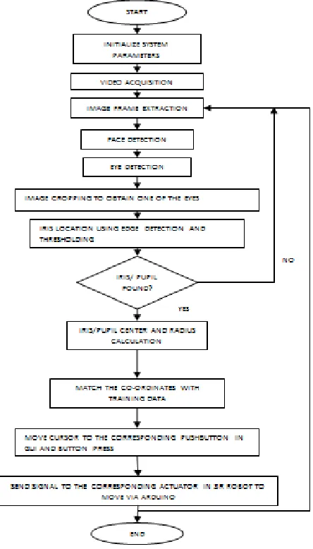
MATLAB software was used for the implementation of eye gaze tracking algorithm. The flow chart of the operations performed for gaze tracking and mouse pointer movement in MATLAB has been represented below [fig.1].
A. Video Acquisition
Video Acquisition is defined as the process of collecting visual information using a video camera by converting the analog video signals into digital form. It is a combination of video capturing, analog to digital conversion, encoding and color space conversion to generate data in any of the several color spaces available such as RGB, YCbCr, etc. as per requirement. In this project, Video Acquisition was used to capture continuous real time images of the user to track his eye movement. This video was captured using a stationary USB video camera mounted on top of the PC and stored in RGB colorspace.The real time video was captured using USB webcam (iball C8.0). A video object obj was created to store the captured video using resolution 1280x960 for high quality image. This configuration works at an average frame rate of 10 frames per second. The trigger configuration was set to manual and FrameGrabInterval was chosen as 5.
B. Frame Extraction in MATLAB
A video is actually a set of multiple image frames that appear one after the other continuously at high speed. When the rate of change of frames per second is greater the perception of vision of a person, looking at the images on screen gives him a sensation of motion. In order to perform image analysis on a video file for tasks like object detection, it is necessary to extract image frames from the video file at a constant rate. This rate can be user defined based on the operations required to be performed on the frames. Matlab consists of some predefined functions for reading an input video file and extracting image frames from it at a required rate. The FrameGrabInterval property in Matlab was used to specify how frequently a frame had to be picked up (grabbed) from a continuous video for analysis and processing.
C. Face Detection in Image Frame
In order to detect the eye movement, the first step was to detect the face of user and separate it from the remaining part of the image. Face detection is a computer technology that finds the locations and sizes of human faces in any arbitrary (digital) images. It detects facial features such as mouth, eyes, nose etc., and ignores anything else which appear in the background. Automatic location or detection of user's eyes is not very easy as there may often be substantial head movements which are undesirable. So firstly finding the location of face, and reducing the range to detect eyes was necessary. Doing this can majorly improve the tracking accuracy and speed, reduce the background effect. Viola-Jones algorithm [8] is fairly robust in terms of head movements, changing lighting conditions, wearing spectacles and the change of hair, etc. therefore this algorithm was used to locate user’s face in this system.
D. Eye Detection
The Viola-Jones algorithm was implemented for face detection in the image. This algorithm not only detects the facial region in an image, but is also capable of finding the eye region accurately as it is a feature based detection algorithm. Thus it was used to locate both the user’s face as well as eye region in the video frames that were extracted continuously. This was followed by putting a Bonding box around the eye region n measuring the enclosed area. This area was then divided into half and resized to display the right eye in a separate image. Similar operations can be performed to track the left eye as well. The image was simultaneously converted into a grayscale image.
E. Iris and Pupil Detection
ii. Hough Transform for Iris Center and Radius Calculation - After thresholding and edge detection, Circular Hough Transform was applied to the binary image to detect the dark circular region in the image and to calculate its center and radius. The radius range for search was defined to lie between 5 to 15 pixels. This range may vary with change in camera and image resolution. Among multiple circles detected, the strongest candidate was selected and its center as well as radius value were stored in an array. This region was encircled in the image in blue color and defined as the pupil region in the eye image. Since the iris and pupil are roughly concentric circles in human eye, their centers co-inside. The center co-ordinates thus calculated gave the desired gaze point
F. Creating GUI
A graphic user interface was designed in Matlab using the guide tool. This GUI consisted of 9 pushbuttons, each for a particular operation of the 3R robot. 6 of the buttons were designated for the actuator movements while the remaining 3 were to start and stop the serial communication to Arduino Uno board via USB cable and to go to home position. After Arduino interfacing, this GUI was used to send signals to the robot through Arduino controller
G. Computing the gaze position
Through continuous observation of eye movement and the corresponding iris center co-ordinates, training data was obtained for few distinct eye movements such as Left, Right , Up and Drown. These training data were used to generate 4 x and y values for each button in the GUI that would be activated if similar x and y values are found during runtime. Euclidean distance was calculated between the measured coordinates and all the training coordinates to find the minimum distance and hence the best fit pushbutton to be pressed. Here, X1 and Y1 defined the pixel values of each pushbutton on display screen where the cursor was to be moved to activate it.
H. Mouse Control
The cursor movement was controlled as per the X1 and Y1 values generated, and the corresponding pushbutton was pressed and released. This led to the robot movement according to the button pressed. All the communication with the 3R robot was done serially through Arduino by storing values in the Arduino object. Thus when the pushbutton was pressed, the corresponding dc servo motor was activated and rotated in the predefined direction encoded for that button. The Arduino board was connected at COM6 serial port of the computer. The servo motors were connected at the pins- 9, 10 and 11 of the Arduino board. Power was supplied to the robot’s actuators (motors) through an adapter via Hi-Link AC-DC converter for rectification of 220V ac to 5V dc supply.
IV. EXPERIMENTAL RESULTS
A. Experimental Setup
Fig 2: Experimental Setup
B. Eye Detection
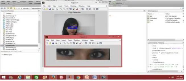
The screenshot showed below [fig.3] depicts the output of Viola-Jones algorithm implemented using Matlab. The Eye region has been cropped and bound from the given image.
Fig 3: Eye Detection Using Viola Jones Algorithm
C. Thresholding and Circular Hough Transform Output
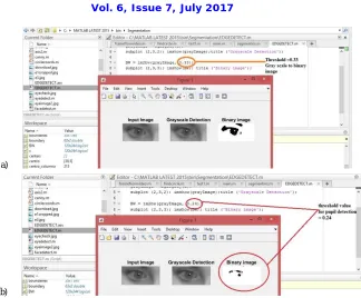
The webcam was modified into an infrared light detection camera by removing its infrared filter. This enabled better detection of the iris and pupil region in the presence of a Near-Infrared source of light (NIR LED). Thresholding was then performed to obtain the iris and pupil region from the eye image as shown below [fig.4]
3-R Robot
H-Link Power Supply Module
iBall C8.0 webcam
Arduino Uno Microcontroller MATLAB GUI
Cropped Eye Image
a)
b)
Fig 4: a) Thresholding of the eye image with threshold value= 0.33 for iris detection, b) with threshold value = 0.24 for iris detection
Similarly results were obtained by implementing Circular Hough transform to calculate the center and radius of pupil in the presence of NIR LED [fig.5]. The configurations used for pupil center calculation are mentioned below [Table 1]:-
Table.1 Configurations for pupil center and radius calculation.
Threshold 0.22 – 0.35
Search Radius (pixels) 5-15
Luminous Intensity 200-250 lux
Detection time 2.54 seconds approx.
Eye distance from camera 30-35 cm
The following limitations were imposed on the system for proper functioning:
i. The detectable eye (here right eye) should lie in alignment with the camera lens and within 30-35 cms from it.
ii. The user should have perfectly functional eyes.
iii. The user should not be wearing glasses; however he can wear transparent contact lenses if necessary.
iv. The room illumination does not fluctuate substantially.
D. GUI Interfacing
The GUI used to control the robot using eye movement is shown below [fig.6]. Each push button corresponds to a particular control function. The pupil center coordinates calculated above are mapped onto the GUI buttons by calculating the location of each button on screen. The HOME push button corresponds to the default position of each link and joint of the robot which can be defined by the user in advance.
a)
Start serial data transfer to arduino
Move MotorM1 clockwise
Stop serial data transfer to arduino
Move Motor M13clockwise
Move MotorM2 clockwise
Move MotorM3 anti-clockwise
Go to home Move MotorM1
anti-clockwise
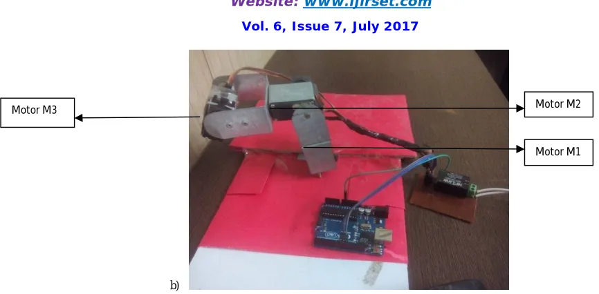
b)
Fig 6: a) GUI with push buttons and their function, b) location of the three dc servo motors in the 3R robot
V. CONCLUSIONS
This paper presented a technique to control a 3R robot with 3 degrees of freedom (rotational) using the eye movement of the user captured by a USB camera. The x and y co-ordinates of the iris and pupil center have been used as a parameter to measure the gaze position with respect to the stationary camera. The system was tested on 5 candidates of variable age groups ranging from 25 to 60 years. While the algorithm was able to track eye movement in all the candidates, the exact gaze position was detected with an average accuracy of 65%. Also horizontal movement was detected more efficiently than the vertical once.
Ambient light also played a key role in proper detection. Both iris as well as pupil tracking was performed without infrared source of light and with it as well. Infrared light was found to be more suitable for detection if the camera and the NIR LED were placed closer to the eyes. On the other hand, non infrared detection using iris tracking gave better results when the camera was placed at a farther distance. The experiment was performed using a Dell laptop with Intel core i3 processor as well as the one with i7 processor. Tracking speed as well as execution speed increased substantially using the later due to its fast processing speed.
REFERENCES
[1] Nicholas J. Wade, Benjamin W. Tatler “Did Javal measure eye movements during reading?” Journal of Eye Movement Research, 2010, 2(5):5,
page no.1-7, ISSN 1995-8692
[2] Huey Edmund Burke “The psychology and pedagogy of reading; with a review of the history of reading and writing and of methods, texts, and
hygiene in reading” Published 1968
[3] Buswell, G.T. “Fundamental reading habits: A study of their development.” Chicago, IL: University of Chicago Press, 1922
[4] Alfred Lukyanovich Yarbus, “Eye Movements and Vision” (1967) Available online at
http://wexler.free.fr/library/files/yarbus%20(1967)%20eye%20movements%20and%20vision.pdf (accessed on 11th June 2017)
[5] F. S. Samaria, A. C. Harter. “Parameterization of a stochastic model for human face identification”. In: Proceedings of the 2nd IEEE Workshop
on Applications of Computer Vision, Sarasota, FL, 1994, pp.138-142.
[6] A. Yuille, P. Hallinan, D. Cohen, “Feature extraction from faces using deformable templates”, International Journal of Computer Vision 8 (2)
(1992) pp. 99-111.
[7] K. M. Lam, H. Yan. “Locating and extracting the eye in human face images.” Pattern Recognition, Elsevier Science ltd. Vol.29(5) (1996)
771-779.
[8] VIOLA, P. – JONES, M.: “Robust Real-Time Face Detection”, International Journal of Computer Vision 57(2), 2004, ISSN 0920-5691.
[9] Paul Viola and MichaelJ. Jones, “Rapid ObjectDetection using a Boosted Cascade of Simple Features”. IEEE CVPR, 2001
Motor M3 Motor M2
[10] J. Daugman. “High confidence visual recognition of persons by a test of statistical independence.” IEEE Transactions on Pattern Analysis and Machine Intelligence, Vol. 15, No. 11, 1993.
[11] R. Wildes. “Iris recognition: an emerging biometric technology.” Proceedings of the IEEE, Vol. 85, No. 9, 1997.
[12] H.K Yuen, .J. Princen, J. Illingworth, and J. Kittler. "Comparative study of Hough transform methods for circle finding." Image and Vision Computing. Volume 8, Number 1, 1990, pp. 71–77.
[13] Uzma Siddiqui, A.N Shaikh “An Overview of Electrooculography” International Journal of Advanced Research in Computer and
Communication Engineering Vol. 2, pp. 4328-4330, 11, November 2013 ISSN: 2319-5940
[14] Tibor Moravčík, Emília Bubeníková, Ľudmila Muzikářová. “Detection of determined eye features in Digital Image.” International Journal of Engineering, 2011,Vol.1,(ISSN 1584-2665)
[15] Thesis on “Recognition of Human Iris Patterns for Biometric Identification” by Libor Masek, The University of Western Australia, 2003
[16] Chinese Academy of Sciences – Institute of Automation. Database of 54,601 iris. Available online at:-
http://biometrics.idealtest.org/dbDetailForUser.do?id=4 Version 4.0. (accessed on 6th June 2017).
[17] Feng, L.; Sugano, Y.; Okabe, T.; Sato, Y. “Adaptive linear regression for appearance-based gaze estimation.” IEEE Trans. Pattern Anal. Mach.
Intell. 2014, 36, 2033–2046
[18] Ghassan J. Mohammed, Bing-Rong Hong, Ann A. Jarjes. “Accurate pupil features extraction based on new Projection Function.” International
Journal of Computing and Informatics, Vol. 29, 2010, pp. 663–680
[19] Sheng-Wen, S.; Jin, L. “A novel approach to 3D gaze tracking using stereo cameras.” IEEE Trans. Syst. Man Cybern. Part B-Cybern. 2004, 34,
234–245.
[20] Lee, J.W.; Cho, C.W.; Shin, K.Y.; Lee, E.C.; Park, K.R. “3D gaze tracking method using purkinje images on eye optical model and pupil.” Opt.
Laser Eng. 2012, 50, 736–751.
[21] M.S.Ghute1, A.A.Parkhi , K.P.Kamble, Mohsina Anjum. “Iris Movement Detection by Morphological Operations for Robotic Control.”
International Journal of Engineering Science and Innovative Technology (IJESIT) Volume 2, Issue 4, July 2013
[22] Craig Hennessey, P. L. (2009). “Noncontact binocular eyegaze tracking for point-of-gaze estimation in three dimensions.” IEEE Transactions
on Biomedical Engineering, 56(3):790–799.v
[23] M R Rajput, G S Sable, "IRIS biometrics survey 2010–2015", Recent Trends in Electronics Information & Communication Technology (RTEICT) IEEE International Conference on, pp. 2028-2033, 2016.
[24] Abid Abbasi. “Towards Fast Iris Segmentation for Real-Time Recognition.” International Journal of Engineering Research & Technology
(IJERT). ISSN: 2278-0181.Vol. 3 Issue 5, May – 2014
[25] J. R. LaCourse and F. C. Hludik Jr., “An eye movement communication-control system for the disabled,”IEEE Trans. Biomed. Eng., vol. 37,
no.12, pp. 1215–1220, 1990
[26] Margrit Betke, James Gips,Peter Fleming ,“The Camera Mouse: Visual Tracking of Body
[27] Krasula, L., Klíma, M., Rogard, E., Jeanblanc, E. “MATLAB-based applications for image processing and image quality assessment – Part I:
Software description”. Radioengineering, 2011, vol. 20, no. 4, p. 1009 – 1015.
[28] Raquib Buksh, Soumyajit Routh, Parthib Mitra, Subhajit Banik, Abhishek Mallik, Sauvik Das Gupta, “MATLAB based Image Editing and
Color Detection” International Journal of Scientific and Research Publications, Volume 4, Issue 1, 1 ISSN 2250-3153, 2014.
[29] Wang, Z., Bovik, A. C., Sheikh, H. R., Simoncelli, E. P. “Image quality assessment: From error visibility to structural similarity.” IEEE Transactions on Image Processing, 2004, vol. 13, no. 4, p. 600-612.
[30] Kawaguchi, T., D. Hidaka and M. Rizon, “Detection of eyes from human faces by Hough transform and separability filter.” 2000. Proc. of
IEEE ICRP, 1: 49-52.
[31] H.K Yuen, .J. Princen, J. Illingworth, and J. Kittler. "Comparative study of Hough transform methods for circle finding." Image and Vision Computing. Volume 8, Number 1, 1990, pp. 71–77.
[32] B. Siciliano and O. Khatib, editors.” Handbook of Robotics”. Springer, 2008.
[33] Niku .Saeed B, “Introduction to Robotics: Analysis, Systems and Applications”.Published by Wiley, Second edition, 2011
[34] Harika Nanduri, Dr. Manoj Soni, “Vision Controlled Pick And Place of Moving Object By 3R Robot” International Journal Of Advanced