On the design of a mobile e-health platform –
towards deployment flexibility
Niels Backx
Thesis for a Master of Science degree in Telematics
from the University of Twente, Enschede, The Netherlands,
15 February 2006
On the design of a mobile e-health platform –
towards deployment flexibility
Niels Backx
Thesis for a Master of Science degree in Telematics
from the University of Twente, Enschede, The Netherlands,
15 February 2006
A
bstract
Almost all industries benefit from the information technology era, including the healthcare industry. In the area of telemedicine, high bandwidth communication technologies enable the transmission of a patient’s vital signs from one location to the other, for analysis and monitoring. Recent developments in mobile communication technologies allow remote mobile patient monitoring: a patient can be monitored without being bound to a specific location. Several projects have been targeting this area, including the MobiHealth project, which aimed at developing a versatile mobile monitoring platform that was suitable in many remote monitoring scenarios. Such a platform is called a mobile e-health platform.
Although MobiHealth aimed at developing a mobile e-health platform, its primary goal was proving the feasibility of such a platform using current mobile communication technologies. The implementation of the MobiHealth prototype is not flexible enough to support a variety of scenarios, without requiring extensive additional design and implementation effort. However, there is a need for such a flexible platform within the Awareness project and possibly future projects.
The mobile e-health platform is a software infrastructure that supports a patient equipped with a mobile device called Mobile Base Unit (MBU) that gathers vital sign data from sensors using short-range wireless technologies (i.e. Bluetooth). The device can communicate using 2.5/3G mobile communication technologies, like GPRS and UMTS, which provide sufficient bandwidth for a set of vital signs, but can be unreliable and are often restricted by the operators. To address these problems and other challenges, the design uses the University of Twente’s Mobile Service Platform, which is based on the JINI Surrogate Architecture.
Our design focus is flexibility and to support this, we identified four flexibility aspects for the platform: (1) the sensors that can be connected to the MBU, (2) the lower level communication protocol used for communication, (3) the functionality included in the MBU and (4) the exact service exposed to client applications. This flexibility allows the design to support various usage scenarios, for which the mentioned aspects must be addressed separately.
The major changes in comparison with the MobiHealth implementation are: (1) the way sensor data is internally handled and (2) the introduction of discrete data types that allows transmission of events and data blocks separately from the sensor data stream. We also used (3) a more component-based design approach, which resulted in a clear structure and allows future developers to focus on a specific component and enables separating responsibilities in a project.
T
able of Contents
1 INTRODUCTION... 1
1.1 BACKGROUND... 1
1.2 MOTIVATION... 2
1.3 OBJECTIVES AND SCOPE... 3
1.3.1 Main objective ... 3
1.3.2 Research questions ... 3
1.3.3 Challenges ... 4
1.3.4 Evaluation criteria... 5
1.4 APPROACH... 5
1.4.1 Analysis phase ... 6
1.4.2 Design phase ... 6
1.4.3 Implementation phase... 6
1.4.4 Evaluation phase... 6
1.5 STRUCTURE... 7
2 EXISTING DESIGN AND IMPLEMENTATION...9
2.1 HIGH LEVEL DESIGN... 9
2.1.1 Mobile Base Unit... 10
2.1.2 JINI Architecture and Nomadic Mobile Services... 11
2.1.3 Backend services ... 12
2.1.4 Healthcare professional application... 12
2.1.5 Standard operation ... 12
2.2 CONNECTIVITY... 13
2.2.1 Sensor device to MBU ... 14
2.2.2 MBU to Surrogate ... 14
2.2.3 Surrogate to backend ... 14
2.2.4 Backend to healthcare application... 15
2.3 IMPLEMENTATION STRUCTURE... 15
2.3.1 Sensor Set ... 15
2.3.2 Transcoding chain... 16
2.3.3 Device Implementation... 16
2.3.4 Service endpoints... 17
2.3.5 Pipes... 17
2.4 HISTORY AND CURRENT WORK... 17
2.4.2 Current work ... 18
2.5 CONCLUSIONS... 19
3 REQUIREMENTS FOR A MOBILE E-HEALTH PLATFORM... 21
3.1 USAGE SCENARIOS... 22
3.5 LEGAL REQUIREMENTS, CERTIFICATION & STANDARDS... 32
3.5.1 Legislation ... 32
4.2.2 Using the BAN model in the mobile e-health platform... 43
4.2.3 Proposed BAN model ... 43
6 SURROGATE AND BACKEND ...75
6.4 SURROGATE/BACKEND COMMUNICATION... 81
6.4.1 Connection framework ... 82
6.4.2 Connection setup... 82
6.4.3 Sensor data communication ... 83
6.4.4 Event and data block communication ... 83
6.5 CONCLUSIONS... 83
8.1.3 Reflection on evaluation criteria ... 97
8.3.2 In research area ... 102
ACRONYMS... 104
BIBLIOGRAPHY... 105
WEB REFERENCES... 108
APPENDICES... 109
APPENDIX A EXAMPLE CONFIGURATION... 110
APPENDIX B EVALUATION OF REQUIREMENTS... 112
APPENDIX C MOBIHEALTH TRIAL DESCRIPTIONS... 114
APPENDIX D PROTOTYPE PACKAGING... 117
L
ist of Figures
FIGURE 2-1HIGH LEVEL DESIGN FOR THE MOBIHEALTH SYSTEM... 9
FIGURE 2-2CONNECTIVITY OVERVIEW FOR THE MOBIHEALTH SYSTEM... 10
FIGURE 2-3SEQUENCE DIAGRAM FOR THE CURRENT SYSTEM... 13
FIGURE 2-4MOBIHEALTH IMPLEMENTATION STRUCTURE... 15
FIGURE 2-5MOBIHEALTH TRIAL EQUIPMENT... 18
FIGURE 3-1TOP-LEVEL USE CASE DIAGRAM... 27
FIGURE 4-1GENERIC COMPONENT DECOMPOSITION [VIS02] ... 37
FIGURE 4-2OVERVIEW FOR THE MOBILE E-HEALTH PLATFORM... 38
FIGURE 4-3PLATFORM COMPONENT DISTRIBUTION... 40
FIGURE 4-4COMPONENT INTERACTION... 40
FIGURE 4-5SYSTEM DECOMPOSITION INTO MAIN COMPONENTS... 41
FIGURE 4-6CURRENT BAN MODEL... 42
FIGURE 4-7CONCRETE BAN MODEL... 43
FIGURE 4-8BANMODEL FOR SENSOR CONFIGURATION... 44
FIGURE 4-9MOBIHEALTH PUSH MECHANISM... 46
FIGURE 4-10MOBIHEALTH PUSH MECHANISM, WITH ACTIVE PIPE... 46
FIGURE 4-11PROPOSED SENSOR BUS MECHANISM (PUSH/PULL)... 47
FIGURE 4-12EVENT STRUCTURE... 48
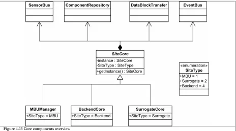
FIGURE 4-13CORE COMPONENTS OVERVIEW... 49
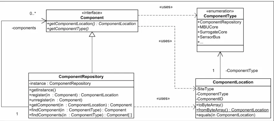
FIGURE 4-14COMPONENT REPOSITORY DESIGN... 50
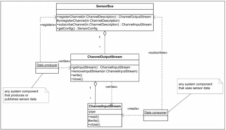
FIGURE 4-15SENSOR BUS STRUCTURE... 51
FIGURE 4-16TIME SEQUENCE DIAGRAM FOR SENSOR BUS OPERATION... 52
FIGURE 4-17EVENT BUS STRUCTURE... 53
FIGURE 4-18SEQUENCE DIAGRAM FOR EVENT SUBSCRIPTION AND PUBLICATION... 54
FIGURE 4-19DATA BLOCK MANAGER DESIGN... 55
FIGURE 4-20GENERIC COMMUNICATION FRAMEWORK... 55
FIGURE 4-21UML DIAGRAM FOR THE COMMUNICATION FRAMEWORK... 56
FIGURE 5-1MBU COMPONENTS AND INTERACTION... 60
FIGURE 5-2PATIENT UML ... 61
FIGURE 5-3DEVICE DRIVER STRUCTURE... 63
FIGURE 5-4DEVICE DRIVER STATE DIAGRAM... 64
FIGURE 5-5PLUG-IN FRAMEWORK... 65
FIGURE 5-6MAIN MBU STATE DIAGRAM... 68
FIGURE 5-7MBURUNNING COMPOSITE STATE DIAGRAM... 69
FIGURE 5-9SENSORRELAYSERVICE OPERATIONS... 71
FIGURE 5-10SENSOR DATA COMMUNICATION OVERVIEW... 72
FIGURE 6-1SURROGATE STRUCTURE... 76
FIGURE 6-2JINIHEALTH SERVICE CLASSES... 79
FIGURE 6-3SERVICE EXPORT FRAMEWORK... 79
FIGURE 6-4GENERIC BACKEND COMMUNICATION SETUP... 82
FIGURE 7-1MBU USER INTERFACE: NETWORK CONNECTIVITY (A), DEVICE CONNECTIVITY (B), SENSOR OVERVIEW (C) AND CHAT SCREEN (D)... 91
FIGURE 7-2BACKEND CLIENT USER-INTERFACE... 92
L
ist of Tables
TABLE 3-1SCENARIO CHARACTERISTICS MAPPED ONTO SCENARIO TYPES... 24
TABLE 3-2TOP-LEVEL USE-CASES DESCRIPTIONS... 28
TABLE 3-3GENERIC REQUIREMENTS FOR THE MOBILE E-HEALTH PLATFORM... 29
TABLE 3-4MBU SPECIFIC REQUIREMENTS... 30
TABLE 3-5BACKEND RELATED REQUIREMENTS... 30
TABLE 3-6NON-FUNCTIONAL REQUIREMENTS... 31
TABLE 3-7APPLICATION DEVELOPMENT REQUIREMENTS... 31
TABLE 4-1MAIN PLATFORM COMPONENTS OVERVIEW... 39
TABLE 5-1XML CONFIGURATION SNAPSHOT... 61
TABLE 5-2MBU STARTUP... 69
TABLE 5-3RELAY PROTOCOL DATA UNIT LIST... 73
TABLE 7-1SITECORE INITIALIZATION CODE AND SENSOR BUS REFERENCE... 86
TABLE 7-2SITE SPECIFIC CORE REFERRALS... 86
TABLE 7-3COMPONENT REGISTRATION AND LOOKUP CODE... 86
TABLE 7-4SENSOR DATA PUBLISHING... 87
TABLE 7-5SENSOR DATA CONSUMING... 87
TABLE 7-6BROADCAST AND UNICAST EVENT PUBLISHING... 88
TABLE 7-7EVENT SUBSCRIPTION AND RECEPTION... 88
TABLE 7-8SENDING AN EVENTPDU ... 89
TABLE 7-9EXAMPLE RECEIVER... 89
TABLE 7-10PLUG-IN CONFIGURATION PARSING... 90
P
reface
The area of telemedicine is an interesting melting pot of medical science and telematics. This thesis is related to only a part of the possibilities that the information and communication technology have opened up for the healthcare industry. Besides the applications that are currently in use or being developed, the future may present even more interesting applications that can increase both quality of care and, in the end, quality of life.
After five and a half years of studying for a Master’s of Science degree in Telematics, this concluding research has enabled me to bring into practice what I have learnt and also brought me into contact with an interesting area that showed me how my knowledge can be used for a real-world application.
In the past eight months I have been able to conduct this research at Yucat Mobile Business Solutions, to which I want to express my gratitude for enabling me to do this work. I especially thank my supervisor Barry Peet and also Frank Thiele for their valuable feedback and reviews of my work. Furthermore, I would like to thank the employees and interns of Yucat for the discussions we had and pleasant working environment they provided.
I also thank my academic supervisors, Aart van Halteren and Ing Widya, for their suggestions, feedback and our valuable meetings.
In conclusion, I sincerely thank my family for their everlasting support and enthusiasm.
Niels Backx
1
I
ntroduction
This thesis presents our research on the design of a mobile e-health platform. Such a platform can be used for a variety of situations in which remote mobile patient monitoring is useful. The thesis focuses on the technical aspects of the design, but touches upon less technical aspects as well. The research was carried out for Yucat Mobile Business Solutions [YUCAT] to provide them with a versatile platform that can be used in current and future research projects and possibly for commercialization.
This chapter presents the background (Section 1.1) and motivation (Section 1.2) for the research and defines our main objective, which is supported by our research questions (Section 1.3). It also provides the approach for our research (Section 1.4) and the last part describes the thesis structure (Section 1.5).
1.1
Background
The healthcare industry has always benefited from using the latest technologies; mostly for increasing quality of care and to contain costs [ZAJ99]. Especially IT is gradually changing the healthcare industry and helps providing health information services and containing costs [GAN04]. The area where healthcare is supported by the use of telecommunication technologies is called telemedicine, which started with simple remote consultation of a medical specialist by phone or videoconference, or by sending patient medical data to a remote location for assessment. Nowadays, it is also possible to transmit live patient data from one hospital to another hospital where a specialist is available, using high-bandwidth telecommunication lines, or less distant, having ubiquitous access to patient data throughout a hospital [NEL97]. Using broadband Internet to the home, even real-time home monitoring of patients is possible.
Telemedicine has three driving forces [ZAJ99]: the first is access to care, telemedicine enables assessment of patients in rural areas who otherwise would not have access to this specialist care; the second force is cost containment, health care expenditures are increasing yearly and technological development often increase the cost; telemedicine can reduce cost by earlier discharge and reduced travel expenses. The third driving force is quality of care, for example, efficient information presentation and remote consultation help general practitioners in making a better and quicker assessment of a patient’s illness. Intelligent systems that accumulate and process patient data from a variety of sources also play an important role for this assessment [BAR99].
domain request, thus its usefulness must be proven and third, insurance companies often require that applications must be proven to be clinically effective before compensated for [ZAJ99].
Mobile data communication technologies like GPRS and more recently UMTS are being deployed throughout the world. Moreover, personal computing devices are decreasing in size and provide portable computing capabilities. These technologies offer the same bandwidth capabilities as early home-monitoring applications used; so combining home-monitoring with these technologies open the latest area in telemedicine: mobile patient monitoring. With mobile patient monitoring, a patient has portable monitoring and communication equipment and his vital signs can be sent to his healthcare professional, reducing the time a patient spends in the hospital [KON02].
Current mobile monitoring systems focus on periodic sending of patient data, or use older technologies with lower bandwidth [KYR03]; often, these systems also focus on a single type of sensor. The European MobiHealth project [MOBIHEALTH], which ended in 2004, aimed at developing a generic platform for continuous mobile patient monitoring that can be used in areas like monitoring during sports training, home monitoring and clinical research [KON02]. This platform links several sensors into a Body Area Network and transmits the sensor data over a single wireless link to the healthcare professional. We call the generic platform as aimed for in the MobiHealth project a mobile e-health platform.
1.2
Motivation
The MobiHealth project trialed the applicability, user-acceptance and feasibility of a mobile e-health platform and its results indicated that there is a need for such a platform and that a stable product is very useful [MH/D5.1]. A generic platform should be flexible at several aspects, like the set of sensors connected to the patient, the functionality provided by the platform or the user-interface of the application the healthcare professional uses to see the vital signs. This enables the platform to be used for a variety of new services in different scenarios. These aspects are defined as implementation flexibility.
Although the mobile data communication technologies are becoming more widespread and although their bandwidth increases; they still suffer from fluctuating speeds and availability due to changing coverage because the user is mobile. A typical set of vital signs data can often be sent using a standard UMTS connection or a good-coverage GPRS connection; however, if the connection degrades, some of the vital signs must be dropped to maintain the real-time property of the data [WID03]. For more complex sets of vital sign data, like a 12-lead ECG, it is often required that as much data as possible is sent, to allow correct assessment of a patient. Both situations demand certain flexibility in the set of vital signs being transmitted at run-time. This flexibility is defined as run-time flexibility.
context-aware applications use context information (like location or presence) to provide services or execute complex tasks; more information on context-awareness can be found in [DOC04].
To support integrating the Awareness functionality in the mobile e-health platform and to work towards a platform that is usable for future projects and possibly commercial deployment, it is necessary to revise the MobiHealth platform. In this research, we will revise the MobiHealth platform and focus on the flexibility requirements, such that it can be used in the Awareness project as well as for future projects.
1.3
Objectives and scope
This section describes the main objective for our research and determines the scope. The main objective is split into three research questions that must be answered to accomplish our objective. Furthermore, we define some challenges that are encountered in the design of a complex distributed platform. Using our research questions and design challenges, we identify some evaluation criteria to evaluate our end-result.
1.3.1
Main objective
Based on our research motivation we define our main objective as follows:
“Design a mobile e-health platform that can be implemented and deployed using available technologies and contains sufficient run-time and implementation flexibility to support a variety of scenarios in which remote patient monitoring can increase quality of care, using the design of the MobiHealth system as a reference.”
The result of this research is a structural design of ‘our’ mobile e-health platform that defines important components and scenario independent aspects of such a platform. We have included ‘using available technologies’ to ensure it can be implemented in the short term. The design presented in this thesis contains the basic functionality for the mobile e-health platform and when implemented, it will present a very light-weight version of the platform. Additional functionality that is required for more complex scenarios is left for future work.
Due to time constraints, we will focus on defining the main components and their behaviour, but will not elaborate on the component-implementation. However, we will verify and test our findings by implementing a prototype. This prototype does not contain extensive error-handling nor is it extensively tested with regard to performance, scalability and stability. The design of the healthcare professional application and the patient’s user-interface are also ignored for this research, since this requires extensive interaction with the users and is very scenario dependent.
1.3.2
Research questions
To reach our objective, we aim to answer the following research questions; the first two are related to the design of the platform and the latter is used to verify this design. For each question, we have included the main tasks that are necessary to give an answer to these questions.
a. List scenarios that cover different aspects of remote patient monitoring and that are representative for a variety of remote patient monitoring situations.
b. Perform a requirements analysis for the mobile e-health platform, using scenario definitions and technical restrictions.
(2) To what extent can the current design and implementation of the existing MobiHealth system be used to work towards a design and implementation of a mobile e-health platform that supports the required flexibility?
a. Analyse the MobiHealth design and implementation.
b. Design the mobile e-health platform, using available technologies. c. Implement a prototype of the design.
(3) Is the design suitable for the scenarios as defined in (1) and what is necessary to implement a specific scenario?
a. Verify the design using the requirements from (1b) and use the prototype to demonstrate the capabilities.
b. List the tasks that are left for scenario developers / system integrators.
1.3.3
Challenges
The mobile e-health platform is a complex distributed application and designing such an application involves design challenges, some of which have already been addressed within the MobiHealth project. This section identifies the main challenges and lists some problems that add extra challenges to our research.
Challenge 1:Gain sufficient domain knowledge to be able to understand the requirements of the end-user.
We have limited domain knowledge on the subject of healthcare and telemedicine; this is a potential problem, because it is important to understand what the end-user requires and to identify priorities in the platform. Although it is impossible to become an expert on telemedicine within the limited timeframe that we work in, we can gain some domain knowledge by studying literature and talking to experts. The deliverables for the three related projects HS24, Awareness and MobiHealth provide a good source for this domain knowledge, especially the usage scenarios and trial descriptions give us insights in what the system is used for. Several medical parties, like medical centres and research institutes, were involved in these projects.
Challenge 2:Deduce sufficient implicit design knowledge that is embedded in the MobiHealth implementation, such that it can be used for our research.
As said, the MobiHealth project forms the base for our design effort; because we did not personally contribute to this project, we have to study the results of the MobiHealth project. Due to the lack of design and implementation documentation, we have to study the implementation thoroughly to deduce the design and the implicit knowledge that is included in this design.
Challenge 3:Work towards a run-time and implementation flexible platform that can be used for a variety of scenarios, while minimizing design complexity.
therefore we have to determine what aspects of the platform must be flexible, both on run-time as implementation flexibility.
Challenge 4: Minimize resource usage at the PDA to allow additional features
To keep the system portable and mobile, we will use a Personal Digital Assistant (PDA) as the main processing unit. PDA’s have limited resources (although their capabilities increase rapidly). If our base platform would consume too much processing and storage resources of the PDA, future extensions such as digital signal processing are inhibited. Also battery consumption plays an important role for a mobile device; if the battery needs to be charged too often, it will decrease the mobility of the patient. Battery consumption depends on both wireless communication and processor usage.
The evaluation criteria in the next section help us verifying if we have overcome these challenges.
1.3.4
Evaluation criteria
This section defines evaluation criteria that are derived from the main objective, research questions and challenges. The criteria are used to evaluate the design of the mobile e-health platform and help answering the research questions and verifying if we have accomplished our main objective.
Flexibility
Flexibility is one of the main focus points in the design; the following criteria are used to evaluate the flexibility of the design:
• The designed platform must support the scenarios and trials that are defined for the MobiHealth and Awareness projects, since the HS24 trials are very similar to the MobiHealth trials, we will not include these for our evaluation and assume that they are supported when the other scenarios are;
• The design must support run-time flexibility with regard to enabling and disabling sensors on-the-fly; • The design must include implementation flexibility, such that it is possible to use different sensors for each
scenario and use scenario specific healthcare professional applications;
• When the design is implemented, it must support a very simplistic scenario, which can be seen as a light-weight version of the platform.
Resource usage
Since the system must be able to run using available technologies and based on the fourth challenge that resource usage should be minimized; we define the following evaluation criteria with regard to resource usage.
• The prototype implementation must be able to run at the device that is currently used to run the MobiHealth system;
• CPU usage of a light-weight platform in regular operation (comparable to Awareness trial, without signal processing) must be below 60% at the device currently used in the projects, to leave room for other applications and functionality, like signal processing.
1.4
Approach
1.4.1
Analysis phase
The first step is analysing the work on the MobiHealth platform, because this is the origin of the current application. Awareness deliverables and HealthService24 deliverables also form an important input for our analysis. After this, we will thoroughly study the implementation of the system and try to derive the design from this implementation. The results of this analysis are both domain knowledge and current system knowledge and the results are presented in Chapter 2.
The second step is defining the leading scenarios and some generic scenarios, which we can be used as a reference throughout the research. We use a simplification of the leading Awareness scenarios and trial documentation for the other projects, the descriptions can be found in the first part of Chapter 3.
The next step is to identify the requirements for the platform; we have explicitly chosen to do this after current system analysis, so we can use our domain knowledge. For the requirements phase we will interview experts, talk to developers of the current system and study requirement-related deliverables. We use use-cases to identify the actors, systems and main system behaviour. The results are described in the second part of Chapter 3.
1.4.2
Design phase
For the design phase, we will start by identifying the high-level structure; defining the distributional aspects of the application and use a top-down approach to define the sub-components. We will focus on designing the part that will be deployed on the mobile device; however, we will also look into backend design.
We will then try to implement (parts of) the components to evaluate their design. This enables us to improve the design and can be seen as an iterative process.
The top-level results for the design phase are described in Chapter 4 and we will elaborate on the lower level components in Chapter 5 and Chapter 6.
1.4.3
Implementation phase
The implementation phase consists of combining and improving the prototype components from the design process and developing new components from scratch, working towards a prototype platform implementation. The next step is to test this implementation with regard to the evaluation criteria as defined in this chapter. We will describe the most important parts of the implementation and testing in Chapter 7.
1.4.4
Evaluation phase
1.5
Structure
This thesis is structured as follows:
• Chapter 1 gives an introduction to our research and poses our main research objective, our research questions and challenges;
• Chapter 2 discusses the current implementation and the technologies used in this implementation; • Chapter 3 contains the requirements analysis on which the design is based;
• Chapter 4 introduces our high-level design and the core components in the system, using a top-down approach;
• Chapter 5 elaborates on the design of the mobile base unit, the mobile part of the application; • Chapter 6 elaborates on the design of the surrogate and discusses some parts of the backend design; • Chapter 7 shows the main challenges in our prototype implementation;
2
E
xisting design and implementation
This chapter presents the results of our analysis of the current design and implementation of the mobile e-health platform. The foundation for the implementation that is currently used in the Awareness project [AWARENESS] was built in the MobiHealth project [MOBIHEALTH]; the HealthService24 project [HS24] also uses the results of the MobiHealth project (and source code). Awareness and HS24 have different goals, but share source code. The design we examined for this chapter has been used for the first beta release of the HS24 and was the core for the Awareness project at that time. For the remainder of this thesis, we will refer to this design as the MobiHealth design, or simply MobiHealth.
We will start our analysis by showing the high-level design, where the main entities in the system are described. Then we discuss the different connections in the system, including the technologies used. The third part describes the most important parts of the implementation of the system. Then we give an overview of how the MBU application evolved and we end with a conclusion on the current design and implementation.
2.1
High level design
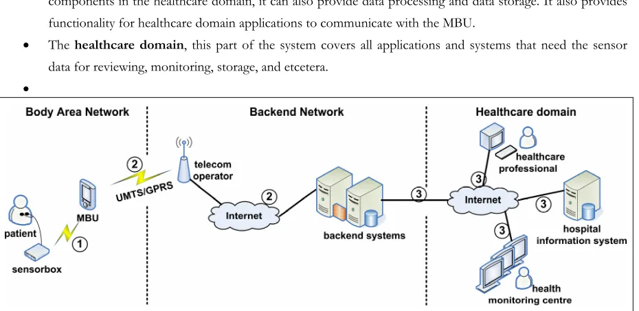
Figure 2-1 shows the overall system design for MobiHealth; its main components are the Mobile Base Unit (MBU), the backend network and the healthcare application. The MBU is the device that the patient carries, the healthcare application is an application that a healthcare professional uses to view the data sent by the MBU and the backend network is the backbone to which the MBU and the healthcare application connect. The backend network is usually protected by a firewall, to secure the patient information. This firewall must allow the MBU to connect to the surrogate host and must allow the healthcare application to connect to the backend service.
The initial system design aimed for flexibility for multiple devices and different types of back-end functionality, but since the TMSi Mobi-device and the associated TMSi PortiLab application were already available [TMSI], the actual implementation mainly focuses on collaborating with these components.
Figure 2-2 shows the communication protocols used between the components of the MobiHealth system. The MSP interconnect and RMI push protocols are the most important ones, since these are defined within the system and can be changed if necessary, whereas the Bluetooth connection between the (Mobi) sensor box and the MBU uses the TMSi fibre-protocol [BRO03]. RMI is Remote Method Invocation, which is a Java standard for remote procedure calling, the RMI push mechanism indicates that the surrogate calls a method at the backend service. If it would be the other way around, it would be called RMI pull. The backend protocol is arbitrary and depends on the backend service and healthcare application. Currently, this backend protocol is a simple raw TCP stream of sensor data.
Figure 2-2 Connectivity overview for the MobiHealth system
The patient side of the system is often called the Body Area Network; the services that are always online are located in the Backend Network and the healthcare application usually runs in the domain of a hospital or general practitioner (GP), which is called Healthcare Domain.
2.1.1
Mobile Base Unit
The Mobile Base Unit or MBU is the PDA or other mobile device that runs at the patient-side of the platform. It is connected to the devices that provide sensor data on one side, and it is connected to the Internet over a 2.5/3G network on the other side. It is also possible to use other wireless technologies, like WiFi.
The devices that provide sensor data can be of different types, actuators are not supported. For patient data, only the Mobi devices by TMSi are being used extensively. Yucat has implemented GPS functionality that shows the location of the MBU in GPS coordinates, but this is currently not embedded in the system. Devices can be connected to the MBU by any communication means available on the MBU; however, each device requires a connectivity module. The Mobi only supports Bluetooth communication, which requires platform dependent (non-Java) communication with the operating system. Yucat has implemented a library called the BTStreamer that facilitates this communication for a Windows Mobile device.
For usability, the MBU also contains a Graphical User Interface (GUI). The GUI is decoupled from the JavaCore to allow different implementations of the GUI for different scenarios. It also allows the GUI to be implemented in a different programming language than Java. The communication between the JavaCore and the GUI is implemented using XML-RPC, a standardized simple remote procedure call technology that uses XML to encode the requests [XMLRPC].
2.1.2
JINI Architecture and Nomadic Mobile Services
In a nutshell, JINI is a service discovery architecture designed by SUN, which enables developers to create adaptive networks and services; it is a specific implementation of the Service Oriented Architecture (SOA). In JINI, a service registers itself on start-up at the JINI Lookup Service (LUS), so it can be discovered. A client locates the service in this LUS and downloads a proxy to communicate with that service [JINIWEB]. Section 6.2.1 elaborates on JINI services in a mobile e-health platform.
Nomadic mobile services are services that are offered by a mobile device; they are called nomadic because regular mobile services are often associated with services that are offered to mobile devices. A nomadic mobile service may constantly change location and as a result may have a changing network address and frequent loss of connectivity. Mobile devices also have limited or expensive bandwidth, so data exchange should be minimized. The JINI architecture defines some strict criteria (e.g. fixed IP address, no network address translating (NAT)) for a service to join the network; a nomadic mobile service does not meet all these criteria and can therefore not join a JINI network on itself. Therefore SUN has introduced the Surrogate Architecture as an addition to JINI [SUN03].
The surrogate architecture defines an architecture that allow services to join a JINI network, which otherwise could not join. Within the architecture, a so-called surrogate joins the JINI network on behalf of the real service. This surrogate uses the facilities of the surrogate host, which provides an environment for executing the surrogate from a host-capable machine. The environment offered meets all criteria that are required for joining a JINI network. The surrogate communicates with the (nomadic) service via an interconnect protocol and is loaded in the surrogate host when the service is running. Service users locate the surrogate of the service in the JINI network and communicate with the service via the surrogate.
In MobiHealth, the MBU and the related MBU surrogate provide the nomadic mobile service. The HTTP interconnect protocol provides the communication between the MBU and the surrogate (explained in section 2.2.2). More information on the JINI architecture and Nomadic Mobile Services can be found in [TOL05] and [ESU05].
JINI was chosen to solve some technical challenges for MobiHealth platform and which are applicable for a mobile e-health platform in general, these challenges are listed below [DOK03]:
• MBUs are ambulatory and can come on-line and go off-line at any point in time; a list of on-line MBUs must be available at the backend. JINI solves this problem via the lookup server that provides discovery methods. • The MBU has limited resources and can therefore not join a JINI network; the surrogate architecture allows
• The MBU can not offer a reliable connection to backend applications; using the surrogate architecture, this problem only needs to be solved once;
• The mobile e-health platform must be scalable and should support potentially thousands of MBUs; JINI networks are designed to be scalable.
2.1.3
Backend services
Backend services are used as a bridge between the healthcare applications and the surrogate. Currently, the two most used servers are: the BAN Streaming Service (BSS) and the BAN Data Repository (BDR). The first enables a user to view the sensor data real-time in PortiLab by putting the raw data on a socket. The second stores raw data for every session in which the MBU sends data, so it can be reviewed later (offline). The services are implemented as JINI clients, meaning they can use the LUS to locate an MBU (represented via the surrogate) and subscribe for its data.
The BDR waits for new surrogates to join the LUS and immediately subscribes for the sensor data, it writes the incoming data to a file. This file is published when the MBU session finishes, a healthcare professional can select the MBU and the session from within PortiLab (see 2.1.4), and simply downloads the session file from a web server. PortiLab then displays the sensor data as a streaming recording of the sensor data.
The BSS waits for a healthcare professional to login to PortiLab and then requests a list of currently available MBUs in the LUS. The healthcare professional selects an MBU and the BSS subscribes for sensor data at the surrogate for the selected MBU. The BSS opens a socket and PortiLab connects to this socket and receives the sensor data.
2.1.4
Healthcare professional application
The healthcare professional application shows the sensor data for the healthcare professional. Currently, the only application used is TMSi PortiLab, which is a closed-source application. This application has extensive filtering capabilities and is fully compatible with data that the TMSi Mobi devices generate. Unfortunately, it is designed for data from one single device at a certain frequency; a plug-in module facilitates communication to the backend services and is not very flexible. For example, it is not possible to add or remove sensors during a session.
Some research has been done on other types of healthcare professional applications, for example using web services [PRU04], but none of these are currently used in trials. An extensive portal is currently being developed in the scope of the Awareness project.
2.1.5
Standard operation
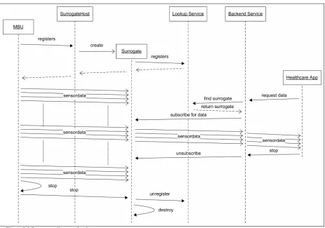
At some moment in time, a healthcare professional wants to see how the patient is doing, so he starts his healthcare application. This application contacts the backend service (in this case the BSS, since he wants to see real-time data) and specifies what patient he wants to see. The backend service contacts the lookup service, asking for the surrogate that is linked to the MBU of the patient. The lookup service returns a proxy for this surrogate and the backend service can now subscribe for the sensor data. The surrogate receives this subscription and relays the sensor data that it receives from that moment to the backend service. The backend service in its turn relays the sensor data to the healthcare application, where the doctor can see the data.
After a while, the doctor shuts down his application, which results in an unsubscribe operation to the surrogate. The surrogate then stops relaying data to the backend service. The MBU will continue to send data to the surrogate.
When the patient wants to stop sending data, he presses the stop button on his MBU and the data transmission stops. The MBU sends a stop-message to the surrogate, which will stop running and will be destroyed by the surrogate host. The MBU is then also shut down, while the servers in the backend network keep running.
Figure 2-3 Sequence diagram for the current system
2.2
Connectivity
2.2.1
Sensor device to MBU
The system is flexible with regard to sensor devices, for each device-type a so called Device Implementation must be written that handles device communication. The Mobi sensor devices communicate to the MBU using Bluetooth, over which it transmits sensor data using the TMSi fibre protocol. A special MBU component called the BTStreamer implements the Bluetooth communication and the fibre protocol and offers the sensor data to the MBU in a stream of fixed-size data packets.
2.2.2
MBU to Surrogate
The communication between the MBU and surrogate is the most important communication part, since it uses unreliable networks (GPRS/UMTS) and has limited bandwidth available. This communication is clearly the bottleneck of the system. The University of Twente has designed a special protocol to facilitate this interconnection between the nomadic service and the surrogate host, which is called the HTTP-Interconnect protocol or MSP Interconnect protocol. This protocol is designed to connect mobile devices to JINI networks; it uses HTTP as an underlying architecture, because many telecom operators only allow HTTP traffic through their networks. More information on this Mobile Service Platform can be found in [ESU05] and [TOL05].
The interconnect protocol offers means to send a request/response and one-way messages from the mobile device to the surrogate and vice versa. It also supports a data stream from the mobile device to the surrogate. MobiHealth uses the messages for connection setup and it uses the data stream for actual sensor data.
The Mobile Service Platform provides some mechanisms to prevent connection loss; however, if the MSP cannot recover from connection loss, the session is stopped and not automatically restarted.
2.2.3
Surrogate to backend
The surrogate to backend communication incorporates usage of the JINI architecture. When a surrogate is initialized, it will export an object as a JINI Service. This object will be serialized and put into the LUS; where it will stay until renewed or removed. The object is a copy of the object that the surrogate had and contains an RMI reference to the actual surrogate.
A backend service locates the MBU in the LUS and retrieves the object that was placed in the LUS. It can now communicate with the surrogate using RMI by calling methods on the surrogate. The system only supports methods for connection set-up and shutdown. At connection set-up, the backend service sends an RMI reference of itself to the surrogate; this enables the surrogate to call methods at the backend service. This is being used for sending actual sensor data packets from the surrogate to the backend service.
2.2.4
Backend to healthcare application
Although the JINI architecture supports that a healthcare application connects directly to the surrogate, this is not used by PortiLab. As explained in section 2.1.3, PortiLab connects to the BSS using a socket for real-time monitoring and uses a file download for historic sensor data.
2.3
Implementation structure
We have thoroughly analysed the implementation of the system; in this implementation we distinguished managing components that dealt with initialization, connection handling et cetera and the components that deal with sending data. Although both types are important for system operation; the data sending components are most important for our research, therefore we will only elaborate on these components. The implementation of the remainder of the system is explained in [YUC05].
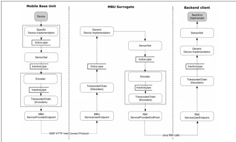
Figure 2-4 shows the data sending components and the data flow, based on the deployment configuration. These are discussed in detail in the following sections. One of the most important aspects of the system is the push mechanism that is used for all components: The device implementation reads data from the device and pushes it into the system. From there on, each component processes the data and then pushes it onto the next component. This leads to a chain of components that are all connected, from device until backend.
Figure 2-4 MobiHealth implementation structure
2.3.1
Sensor Set
sensors to which can be subscribed individually, so that a subscriber only receives the data for that specific sensor. Unfortunately, this functionality is currently not working correctly.
The SensorSet is managed by a SensorSetManager and receives its data from a Device Implementation (see 2.3.3); it then forwards its data to all subscribers. These subscribers can subscribe at two points: the SensorSet itself or at its manager. The main difference is that the SensorSet sends data directly to the listeners, while the manager uses a pipe to buffer the information. The exact reason to have two points to subscribe to is unknown, but probably subscribing to the manager is for listeners that require a lot of processing time or have delays because of communication lines. If the data is processed instantly, the extra pipe does not seem necessary.
2.3.2
Transcoding chain
The transcoding chain is a chain of encoders that can alter the representation of data in the system; this is mostly used for saving bandwidth and CPU power. The transcoding chain is linked to the service provider endpoint that sends data to a peer. All encoders must have a corresponding decoder at the peer, if no decoding is required, the data can be passed through unaltered by the decoder.
The most important encoders currently implemented are:
• Filter: Remove the data of sensors that are not active according to the configuration, this reduces the amount of data sent over the line (e.g. disable a Plethysmogram for a cardio trial);
• Packet: Buffer a certain amount of data samples and forward them in one large packet, reducing the amount of packets sent over the line. The optimal buffer size depends on the communication network used [BUL05], [WAC05];
• Deflate/Zip: Two different implementations that compress the data by using a standardized method, this also reduces the amount of data sent over the line.
As shown in Figure 2-4, the transcoding chain is used twice: once for communication between MBU and surrogate and once for communication between surrogate and backend. If multiple backends are connected they will share the transcoding chain if the same transcoding elements is requested; however if they request a different chain, the surrogate will create a new transcoding chain. The surrogate can thus have multiple transcoding chains at the same time.
2.3.3
Device Implementation
The device implementation has knowledge of the sensors that are attached to it, but this is limited to descriptive information only. The data is immediately forwarded to the SensorSet, where other components can subscribe.
2.3.4
Service endpoints
Service endpoints are the entities that provide connectivity from one location to the other and vice versa. Depending on configuration, these endpoints use a specific protocol to send data; in the current setup, the system uses the MSP Interconnect protocol between MBU and surrogate and uses Java RMI push calls between surrogate and backend clients. Other implementations are currently not in use.
Two types of endpoints can be identified:
• ServiceProviderEndpoint: This is connected to the encoding transcoding chain, so it receives data from the system and sends it over the network using the configured protocol.
• ServiceUserEndpoint: The side that receives data from the ServiceProviderEndpoint and forwards this up into the decoding transcoding chain, so it can be put into the sensorset.
2.3.5
Pipes
At several locations in the system pipes are used to buffer data; data is put in on one side and sent to all pipe-listeners on the other side. These pipes can be configured to be active or inactive.
• Active: These pipes have their own ‘pump’-thread, this causes the source of the data not to block for a while if data is being sent to multiple receivers that possibly do some intensive computation or use blocking socket calls.
• Inactive: These pipes just relay the data to the listeners, running in the same thread as the source of the data.
It is important to have active pipes at strategic locations, such that important operations (like reading new data from the device) do not block or delay too much. However, too many active pipes will cause more threads running in the system; this causes extra overhead. The current settings for active/inactive pipes are based on experiments.
2.4
History and current work
This section describes the history of the MobiHealth application and the (con)current work on the application, which gives an insight into how the application evolved and what major changes can be expected.
2.4.1
History
Yucat has ported a simplified version of the complete PDA application to Windows Mobile using C# .NET to prove that a Windows Mobile PDA was also suitable for running such an application. This feasibility study led to a port of MobiHealth to the Windows Mobile platform, in which the Java core remained intact, while the GUI was replaced with a C# .NET GUI, this is described in [THI05].
The last major change to the application was removing the BAN interconnect protocol into a separate project: the M-health Service Platform (MSP), which evolved into the Mobile Service Platform. The Windows Mobile application that uses the MSP is used for this research and is referred to as the MobiHealth application or the current application. It is also the application that is currently being used in the HS24 and Awareness projects.
Figure 2-5 MobiHealth trial equipment
Figure 2-5 shows the patient equipment for the MobiHealth trials. The device on the left is the HP iPAQ, the box on the upper-right is a TMSi Mobi4 device, which is connected to five ECG leads and an alarm button. Nowadays, the alarm button is on top of the Mobi device and the ECG leads are grouped to reduce the amount of connectors.
2.4.2
Current work
At the moment of writing, several projects are working with the MobiHealth application; the HS24 project aims to stabilize the system and adding some required functionality. The focus of this project is on the PDA application.
The application is also improved within the Awareness project; however, it focuses more on backend development (an integrated portal) and using the application with new technologies, like positioning and context-aware services.
2.5
Conclusions
Studying the system has revealed the complexity of the current implementation. This complexity mainly consists of the large amount of coupling of the code elements. The general design idea was to have code that was flexible with regard to different communication protocols and the same code could be reused at all three locations. This design idea also adds to the complexity; furthermore, some location specific (e.g. MBU) parts of the code are put in a general class that is available throughout the system (at MBU, surrogate and backend).
The current platform lacks documentation and code-comments; as a result much design knowledge has been lost, which makes it difficult to understand the system. This inevitably led to making assumptions about the design rationales at some points of this analysis.
The surrogate architecture with the MSP-interconnect protocol seems to be ideal for the mobile health application, since it supports public mobile networks and solves the standard problems of a nomadic mobile service in a JINI network; however the current implementation does not use all functionality offered by the MSP. The surrogate to back-end communication is based on Java-RMI, and while the connection setup is complex, the actual communication is quite straightforward.
All in all, the complexity causes that locating bugs and solving these bugs is a tedious task. Moreover, making small changes or additions is a time consuming job, since it is hard to predict what classes are affected by these changes. Nevertheless, several patterns and implementation structures are very usable for a stable yet flexible mobile e-Health platform.
For a platform that can be used for various scenarios and that offers a good framework for further development, we do not deem the current implementation sufficient. Therefore we must decide if we want to redesign from scratch, using the design and implementation knowledge gathered from this analysis; or if we want to change the current implementation step-by-step removing the coupling and working towards a platform that satisfies our needs. This decision will be taken based on our requirements analysis for the platform, which is presented in the next chapter.
3
R
equirements for a mobile e-Health platform
This chapter gives an overview of the usage of, and requirements for the mobile e-health platform. These requirements form the base for the design of the mobile e-health platform and can be determined by identifying the needs of the end-users and the future developers of the system. We can distinguish two types of requirements: the end-user requirements and the technical requirements. The first can be derived from scenarios and end-user interviews, while the latter are enforced bottom-up by technological constraints.
One of the most important overall requirements is the flexibility of the platform: it should be possible to use it in a large diversity of scenarios that share the overall goal: monitor a patient and transfer sensor data using wireless technologies to a healthcare service provider and finally to a healthcare professional. Since too much flexibility can result in a complex application, we must find a balance between flexibility and complexity using frameworks and configurability and clearly defining the required flexibility aspects.
The two most important technological constraints are bandwidth and processing power; the used mobile communication technologies do not guarantee a fixed bandwidth and the available uplink is not fast enough to send a large amount of sensor data. Therefore bandwidth usage must be optimized by, for example, disabling low priority sensors. Mobile devices offer limited processing power and processor usage also relates to power consumption; therefore processor must also be optimized.
We have gathered the end-user requirements from existing requirement documentation, talking to (medical) experts within the Awareness project (Roessingh Research & Development [RRD] and Twente Medical Systems International [TMSI]) who have participated in previous trials and to application developers of the MobiHealth system. We have tried to identify those aspects of the system that are necessary to design a platform and tried to keep the list independent of a specific scenario; therefore the list may not seem to be complete for a system, but we think it is sufficient for the design that we consider in this thesis.
3.1
Usage scenarios
Usage scenarios define a situation for which the system can be used; they are often related to a medical condition of a patient, whose quality of life can be improved when he is connected to the mobile e-health platform. The first part of this section describes the leading scenarios for the Awareness project; the second part generalizes these and other scenarios into four scenario categories of which the specific characteristics are determined in the third section. The fourth section discusses the data types that can be distinguished within these scenarios and the fifth section discusses the required flexibility to be able to implement these scenarios using the platform.
3.1.1
Leading scenarios
There are two leading scenarios in the Awareness project [AW/D1.1]; the first is based on a patient who suffers from epilepsy. Epilepsy is a disorder in which nerve cells of the brain, from time to time, release abnormal electrical impulses; so-called seizures. The seizures in epilepsy may be related to a brain injury or a family tendency, but often the cause is completely unknown.
The patient is equipped with a 24-hour seizure-monitoring system that measures heart rate variability and physical activity. Based on these variables, the system should be able to predict future seizures, which can be communicated to relatives or healthcare professionals automatically, together with the location (acquired using for example GPS) of the patient. If possible, the patient himself is warned by the system that a seizure is imminent. The aim of using this system is to provide the patient with both higher levels of safety and independence in order that he may function more normal in society despite his seizures.
The second leading scenario is based on a patient with chronic musculoskeletal pain. The patient is equipped with a system that monitors the patient’s health status and can be used to provide bi-directional feedback. The patient can indicate his current activity and tell the system that he is currently is experiencing pain, so a healthcare professional can tell a patient to change his behaviour. To be able to determine incorrect behaviour, it is important for the health care professional to have detailed vital signs and physical activity measurements
3.1.2
Generalization of scenarios
Although the two scenarios as described above are leading for Awareness, it is important that the platform we design is flexible such that it can be used in a variety of scenarios. Therefore we have analysed the trials and scenarios for the two related projects HealthService24 and MobiHealth and combined these into four generic scenario descriptions, which can be used for further requirement analysis.
Continuous patient monitoring
When using the system for home monitoring, a patient is equipped with a BAN and instructed on its usage. The patient wears the BAN as much as possible and data is sent to the hospital or a data centre, from where it can be analyzed by healthcare professionals (HCP) or specialized backend servers. This is used when the patient suffers some chronic disease or requires some extra monitoring after returning from the hospital.
Temporary patient monitoring
slower. This method can also be used to monitor changes in the patient’s health over a longer period of time, if the activity is repeated in the same setting.
Healthcare professional walk-in
The HCP visits a patient and connects a BAN to the patient; the patient does need to have knowledge of the system. The HCP can then either stay, perform some measurements that are sent into the patient’s electronic dossier and leave with the BAN. Or the HCP can leave the BAN at the patient after ensuring a proper setup and retrieve the BAN a certain period later (24 to 48 hours). During that period, the BAN has sent data to the backend and a HCP can analyze this data and draw conclusions regarding hospitalization, medication etcetera.
Trauma monitoring
A trauma team is equipped with one or more BANs. Upon arrival at a trauma scene, they can connect the patient and send data to the hospital immediately. Hospital HCPs can then monitor the patient and respond accordingly, for example by preparing for surgery, reserving equipment. Moreover, they know the situation of the patient upon arrival. This trial introduces an extra concept to the system: a Vehicle Area Network, or VAN. When a VAN is used, the BAN does not connect directly to the hospital server, but connects to the ambulance. This ambulance contains a router that sends the BAN data to the hospital server, but it may also contain other functionality, like data storage. This VAN was introduced, because in some cases, the Trauma Team may be inside a building or tunnel, where 3G coverage is limited. The MBU sends the data using a medium distance technology, like WiFi to the ambulance and the ambulance has better 3G connectivity.
In this thesis, we will focus on the first three categories and will not look into a VAN; however trauma monitoring may be possible using GPRS/UMTS.
3.1.3
Scenario characteristics
Based on the trial descriptions for MobiHealth [MH/D1.3], HS24 [HS/D3.1] and Awareness [AW/D1.1], we have identified six characteristics that the platform must have to support the trial scenarios. Most possible scenarios for which the system will be used can be described in terms of these properties; therefore they form an ideal basis for defining the platforms requirements.
• Session duration: The duration of a session can range from a patient who needs to be monitored 24/7, for example to notify him of an imminent seizure to a patient who only requires monitoring for a short training exercise.
• Data transmission mode: The data transmission mode indicates whether data should be transmitted continuously, or only after a certain event (e.g. a seizure).
• Data density: The amount of data that needs to be sent; some scenarios suffice with a heart rate and a location, other may require a continuous 8 channel ECG to be transmitted. This can fluctuate within a session, e.g. after a specific event or on request.
• Allowed data delay: The delay is defined as the period between actual data measurement at the patient and the arrival of the data at the screen of the healthcare professional. For inter-active sports scenarios, this delay must be minimized.
• Data types: What kind of vital signs and other data needs to be transferred is discussed in the next section. • MBU operator: In most scenarios, the patient is equipped with an MBU to monitor his personal data, but
For some scenarios it is necessary to make a trade-off in these properties, for example, 24-hour monitoring with minimum delay and maximum data transmission is hard to achieve with current technologies; therefore it is important to prioritize the properties and define system behaviour for each scenario. Table 3-1 maps the characteristics on the generic scenario categories and the leading scenarios. The values are based on regular scenarios that match the generic category.
Duration Data mode Density Delay Operator Continuous Continuous Depends Depends Short if DSP
used
Patient
Temporary Max. 1 day Continuous Depends Short if real-time feedback
Patient
Walk-in Max. 2 days Continuous Depends Depends Healthcare prof
Trauma Max. few hours Continuous High Short Healthcare prof
Epilepsy Continuous Event High Long if DSP at MBU
Patient
Musculoskeletal Continuous Continuous High Short if real-time feedback
Patient
Table 3-1 Scenario characteristics mapped onto scenario types
3.1.4
Characterisation of data
There are several types of data that the system will need to transmit; these can be categorized as follows:
• Continuous vital signs: These vital signs need to be represented as a waveform to be interpreted; it is sometimes also possible to derive other information from these vital signs, for example, it is possible to deduct a heart-rate from ECG measurements.
• Discrete vital signs: These vital signs can be represented as numbers, for example a heart rate.
• Data blocks: These are binary data objects, like images or short videos that are necessary for diagnosis and treatment.
• Events: Events are simple messages from one part of the system to another, for example information on the patient’s activities, an alarm or the patient’s device status.
• Conversation & Questionnaires: It is sometimes necessary for a healthcare professional to give real-time feedback to the patient, and the patient may also be asked to report activities or change in medical condition.
3.1.5
Flexibility
Since flexibility is one of the focus points for our design, we will discuss the two main flexibility axes for the mobile e-health platform. These flexibility axes contain several sub-requirements on flexibility, which we have deduced from the scenario properties and the possible data types that the system transmits. Based on these generic flexibility requirements, we can state the more concrete technical requirements for our platform in the following sections.
a. Defining internal component behaviour: the components designed in thesis must be easily replaceable with an improved version, so functionality must be separated into components;
b. Adding functionality to support new sensor devices: different scenarios require different sensor devices, these may be of a different brand and use different connection protocols;
c. Implementing a new graphical-user interface: the user-interface is very scenario dependent, both the functionality and the graphical design, it must be easily interchangeable;
d. Adding a new lower-level protocol: although the structure of the system will be clearly defined, the protocols used between the distributed components may depend on the security required, the technology used and the efficiency used. Supporting other protocols ensures a clear decoupling of communication concerns from processing logic;
e. Define interface to communicate with backend client applications: the backend client application also depends on the scenario and implementing such an application requires extensive domain knowledge. Since this part of the system is out of the scope of our design, we must ensure that the developers of this application can define their own communication means with the platform. Moreover, it allows other kinds of services to be offered from the device;
f. Add functionality to mobile device: the mobile device supports the generic functionality. Often, extra functionality is required for a scenario, like signal processing, data analysis and et cetera.
(2) Runtime flexibility:the flexibility at runtime defines that the system, while running, must be able to change at least:
a. The vital signs that are read from a device and broadcasted into the system: since processing power is limited, processing unused data is a waste of resources and may increase power consumption;
b. The vital signs that are being transmitted: as with processing power, also bandwidth is limited and sensor data must only be transmitted if enough bandwidth is available and the vital signs is required at the back-end;
c. The communication protocol in use: if the system supports multiple communication technologies, the underlying protocol may be changing at run-time, to ensure uninterrupted sensor data delivery, the communication protocol must be changeable at run-time;
d. Starting or stopping additional functionality, like digital signal processing: if sufficient bandwidth is available, it is possible to send a large amount of vital signs. However, if limited bandwidth is available, the bandwidth usage may be optimized by pre-processing the vital signs by, for example, deriving a heart rate from an ECG. Since this requires processing power, it should be disabled when deriving is not required.
3.2
Use cases
3.2.1
Actors
Within the mobile e-health platform, we have identified five actors that deal with the system regularly. The actors in this case are roles, so it does not need to be a specific person within an organization. The first four actors only deal with the system when it is deployed and will be using the system on a regular basis.
• Patient: The patient is the person that will be monitored using the system. It is assumed that this person has no experience in working with medical equipment, telecommunication equipment or PDA’s;
• Healthcare professional: The healthcare professional (HCP) monitors the patient and is directly involved with the treatment of the patient;
• Voluntary aid person: In some scenarios, a voluntary aid person is contacted by the system in case of an emergency;
• System administrator: The administrator is responsible for managing the devices after system deployment. He is responsible for configuring devices for new patients and keeping track of all devices;
• Application developer: The application developer is responsible for implementing a specific scenario and making adjustments to the core system if this is required by the scenario. This also includes integration into the hospital infrastructure. The developer is a different kind of actor than the previous four, since it deals with the implementation of the system. However, since this research focuses on a platform that will require future work, it is an important actor for our requirements analysis.
When designing use-cases, external systems can also be defined as being actors, we have identified two potential external systems that interact with the platform:
• External patient device: An external patient device is the device that is carried by the patient and provides data to the system. This data can be of any type, for example vital sign data or GPS location;
• Hospital patient management system: Most hospitals have their own patient management system, where patient information is stored. It is very likely that the platform needs to be integrated with these systems and therefore interaction between the platform and this system is required.
3.2.2
Systems
The actors as described above can interaction with the system using the following systems:
• Mobile Base Unit: The MBU is the device that the patient carries; therefore it is a mobile device. It communicates with the backend system and can be connected to external devices. There are multiple MBUs active within the platform, where each patient has one MBU;
• Backend system: The backend system is the part of the system that receives the data from all MBUs and processes this. External hospital systems communicate with this system to retrieve the data they require for the patient files, healthcare professional and administrator applications also use backend functionality; • Healthcare professional application: The healthcare professional uses this application to view patient
sensor data and for communication with the patient. It is connects to the backend system, so it can also be seen as a part of the backend system;
• Administrator application: This application enables the system administrator to manage the devices, it is also linked up to the backend system;
3.2.3
Use-case description
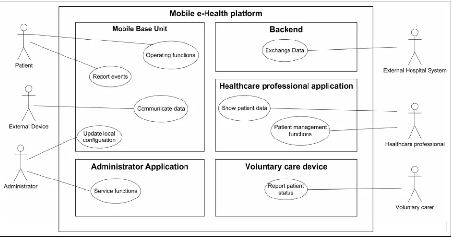
Since exact system interaction relies too heavily on the scenario properties, we will only provide a top level use-case, showing the most common interactions at a highly abstract level. This gives us an overview of the relations between the actors and the systems, as is shown in Figure 3-1. The relations between the healthcare professional and administrator applications and the backend system are not shown.
Figure 3-1 Top-level use case diagram
The table below gives a short description of the use-cases illustrated in Figure 3-1.
# Use-case Actor Description Mobile base unit
(1) Operating functions Patient Defines the operations that the patient can perform on the MBU, like starting a session and reporting activities.
(2) Report events Patient Defines what happens when the system wants to
report an event to the user, for example an alarm or incoming physician message.
(3) Communicate Device Data External device Defines the interaction between the external device and the MBU. The exact interaction is usually defined by the device manufacturer.
(4) Update local configuration Administrator The administrator can change the configuration of the MBU, this use-case defines how.
Administrator applications
(5) Service functions Administrator When the patient runs a session, the administrator can check the configuration and status of the device, and possibly make changes to the configuration.