Tracking of Objects in Video Scenes with Time
Varying Content
Amal Mahboubi
IRCCyN UMR 6597 CNRS EPUN, rue Christian Pauc La chantrerie, BP 60601, 44306 Nantes, France Email: [email protected]
Jenny Benois-Pineau
LABRI, CNRS UMR 5800, Universit´e Bordeaux-1, 33405 Talence, France Email: [email protected]
Dominique Barba
IRCCyN UMR 6597 CNRS EPUN, rue Christian Pauc La chantrerie, BP 60601, 44306 Nantes, France Email: [email protected]
Received 27 July 2001 and in revised form 5 February 2002
We propose a method for tracking of objects contained in video sequences. Each video object is represented by a set of polygonal regions. A bottom up approach (spatial segmentation/motion estimation) is applied for the initialisation of the method, a limited human interaction is used to build the semantic map of the first frame in video sequence. The tracking of this model along a video sequence is based on detecting and indexing new objects in a video scene. Semantic rules are used to label new objects and, the current state of segmentation is validated by forward projection of the background.
Keywords and phrases:new region extraction, labelling, object indexing, forward projection.
1. INTRODUCTION
The new ongoing standard of video representation and cod-ing MPEG4 [1] gives tremendous possibilities for the com-position of heterogeneous video scenes combining video ob-jects of various nature. The main challenge behind MPEG4 technology is the development of efficient and truly au-tomatic methods for extracting and tracking of objects in video. Once video objects are known at each time instant, they can be manipulated, put into another scene and so on. Numerous research works, developed recently [2, 3, 4, 5, 6], are devoted to the problem of automatic tracking of a se-lected video object planes (VOP) in a scene. The focus of study [2] is an object tracking which combines motion and spatial information in order to be able to track objects which do not present either homogeneous texture or motion. The method has been applied to the problem of the generation of video objects for content-based functionalities in object-based coding schemes. To extend this work, [3] presents an interesting technique for generic object tracking. This method perfects the first tracking scheme [2] by projecting region-based partition. This projection accommodates the previous partition information in the current image. Then
the object partition is re-segmented and it is projected on the following image using motion information. Nevertheless, this method assumes that objects have been defined in the first image and the process is not able to correctly detect a new object in the scene. To mitigate those consequences, it introduces the concept of user interaction in the algorithm to handle variation of objects. The works [4, 5] surveyed the region-based active contours approaches. The first study in-troduces the active contour criteria and the second presents the use of a B-spline parametric contours for object track-ing. The temporal gradient is a term of temporal evolution of scene content. Here the principle is based on applying the force based over few contour points, then contour evolution depends only on the evolution of these interpolated points and no more on each point of contour.
the deformation of objects. The spatial segmentation used is based on the minimum description length criterion. Mo-tion compensaMo-tion is performed using affine motion model per region estimated with a multiresolution scheme and re-laxation. The encountered problems of this method are the possible artefacts in spatial segmentation and errors in mo-tion estimamo-tion and in the occlusion areas as well. To remedy to that, a splitting of regions is proposed to correct these arte-facts according to the object definition or prediction error.
But other faces of spatio-temporal segmentation remain unstudied. The main one is an automatic semantic interac-tion between different areas in a natural video scene, that is, the ability to correctly label asobject, new object, background all areas in video scenes with strong changes between succes-sive time instants. In this context, we propose a tracking of objects in video scenes with time varying content.
The method starts with the extraction of video object from a complex natural video scene at the initial time in-stant, using a fine spatial partition of image plane. The geom-etry of each spatial primitive is represented by a piece-wise linear approximation of the border. Affine motion model of each polygonal region is estimated by means of gradient de-scent method. Then all regions are classified semantically by means of human interaction. After that, connected regions are merged in each semantic class to build a hierarchical rep-resentation of the scene using motion homogeneity criteria. The tracking of changed content is based on motion estima-tion of regions along the time and on textural and topological coherence measures.
Correction or confirmation of labelling for the current frame is based on a forward projection of the background taken at specified moments in the sequence.
The paper is organised as follows. Section 2 describes the initialisation of object-based partition of video scenes. Gen-eral tracking scheme is described in Section 3. Section 4 rep-resents the indexing of VOPs in case of time-varying con-tent. Section 5 describes the validation of the automatic la-belling. Finally, the main results of the tracking are presented in Section 6.
2. INITIALISATION OF SPATIO-TEMPORAL PARTITION OF VIDEO SCENES
To extract objects to be tracked, a spatial colour-based seg-mentation of a video frame at the initial time instant is ap-plied. The spatial segmentation is the result of a morpholog-ical method based on modified watershed [7]. It consists of four classical steps of a morphological scheme: image sim-plification, gradient computation, marker extraction, water-shed algorithm. In our approach we especially developed as-pects of the watershed method. After image simplification using reconstruction by opening-closing filters, morpholog-ical gradient is computed [7, 8]. The result of this step is the gradient image which highlights the grey level contours con-tained in the filtered image. Then the marker is extracted, the result here is a binary image (marker image) where 1 repre-sents the pixels with a gradient magnitude lower than a fixed threshold. Finally, region growing by watershed in colour
(a) (b)
(c) (d)
(e) (f)
Figure 1: The process of the spatial segmentation. (a) Original frame, (b) filtered image, (c) gradient image, (d) marker image, (e) watershed image, (f) final image.
YUV space is fulfilled. Namely, each connected area in the marker image is labelled. It represents a seed of future region characterised by its mean colour vector ( ¯y,u,¯ v¯)T
i. Then the seeds are expanding absorbing pixels on their border if their colour distance from mean vector ( ¯y,u,¯ v¯)T
i is less than pre-fixed threshold. This threshold depends on mean colour val-ues of region. After all pixels have merged for a given thresh-old value for each region, the relaxation process with corre-sponding thresholds allows for further merging until all pix-els are labelled in image plane.
The result of the watershed segmentation is too redun-dant as it gives a very fine partition containing several re-gions. Therefore we apply a hierarchical merging based on a relative contrast criteria. Adjacent regions of the final result represent a rich partition of image plane [8]. Figure 1 dis-plays the different steps of the spatial segmentation.
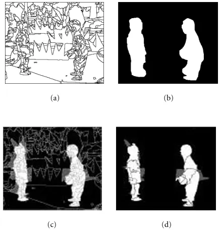
(a) (b)
(c) (d)
Figure2: The process of the first semantic classification. Sequence “Children” frame att=3 (a) spatial segmentation, (b) user mask, (c) first result of the semantic classification, (d) final result of the manual semantic classification and motion-based merging (black for Background, white for the VOPs and grey for Uncertain).
with parameter vectorΘ=(tx, ty, k, θ)T. According to it, an elementary displacement vector (dx, d y)Tat each pixel posi-tion (x, y) in a given region is expressed as
Herexg, yg are the coordinates of the gravity centre of the region,tx,t y, are translation parameters,divis a zoom pa-rameter, androtis a rotation parameter [10].
These regions should be labelled semantically to provide VOPs corresponding to meaningful objects in a scene. Purely automatic labelling is possible only for simple scenes, where a strong difference of the dynamic range and of the textural characteristics of objects and the background is observed. In general case of natural scenes, an object can be partly static and thus, it cannot be distinguished from the background based on motion difference. The colour and texture of object can be similar to the background. Therefore, a user inter-action is required to completely extract objects in a general case. We propose a minimal human intervention. The user creates a binary semantic class mask on the first frame by encircling objects, here we have an image with 0 in the back-ground and 1 inside objects (the encircled area) as shown in Figure 2b. This binary image calleduser maskis then used for the initial VOP labelling.
Each polygonal region (Figure 2a) is superimposed on the user mask (Figure 2b) to get the initial classification (see Figure 2c). Thus the three semantic classes can be intro-duced:
(1) Object: is the class of objects in the scene.
(2) Background: this class denotes generally the scene background.
(3) Uncertain: this class represents the ambiguous area on VOPs borders.
The semantic labelling of each region is based on the ratio of region pixels bellowing to object area in user mask. Denote by ΩRithe set of region pixels which are labelled as object in user mask: ΩRi ={pi ∈ Ri/Mask[pi]= 1}. Also denote byΓRithe set of region pixels belonging to the background ΓRi={pi∈Ri/Mask[pi]=0}. Then, the semantic label ofRi
Here Thobj is the ratio of region pixels inside object mask with regard to the whole number of region pixels; Card de-notes the cardinal of pixel set. An example of this semantic labelling is given in Figure 2c.
The labelled spatial regions constitute a fine partition of the image plane which is too redundant with regard to the scene content (see Figure 2a). Therefore, a motion-based merging process is necessary to construct more meaningful region-based partition. We follow the motion-based merg-ing strategy proposed in [11] to construct a nested hier-archical polygonal partition inside each semantic class (see Figure 2d).
Finally, each VOP is indexed in the video scene by the following method.
Each polygonal region in the image plane corresponds to a region-node in the region adjacency graph (RAG). Starting from an arbitrary Object Class node in RAG, all the graph is traversed by the so-calledIn-Depth Searchalgorithm [12] and the maximal subgraph with only Object Class nodes is isolated. This subgraph corresponds to a connected VOP in the scene. All region-nodes of this subgraph receive a label, Object Index.The process is reiterated for all remaining Ob-ject Class nodes with incremented ObOb-ject Index label.
Resulting from this process, the label of each region in image plane partition is set to Uncertain, Background or its own Object Index value corresponding to the VOP index.
3. TRACKING SCHEME
(i) projecting of polygons in the direction of time axis, (ii) adjusting of predicted borders by an active contour
model,
(iii) segmenting of regions with changed content, and (iv) merging of regions at timet+ 1.
Thus the spatio-temporal partitionSt+1is obtained fromSt. In scenes with changing content, it is necessary to label new regions as belonging to new or preexisting VOPs, to the Back-ground or to Uncertain class. The method presented here in-corporates solutions for labelling the new regions and cor-recting errors of segmentation due to diverging tracking pro-cess in the case of strong motion. The tracking of polygonal partition proposed in [10] can yield the appearance of new regions between timestandt+ 1, which receive new labels. There are two reasons for the creation of new regions in the segmentation map.
When projecting a spatio-temporal partition St to the next frame at step (i) with affine model (1), overlapped and uncovered areas are formed in image plane at time t+ 1. In our previous work [10], we studied in detail process-ing of occlusions in overlapped areas. For these occlusions, their motion-based assignment to already existing regions was proposed. Thus they do not yield new regions. Another situation is observed in case of uncovered areas, which do not have a prehistory. They can appear in the neighbourhood of VOPs. They also appear on the borders of video frames in case of background motion. They can also be observed in-side VOPs (self-uncovered areas).
The second reason of generation of new regions by track-ing method [14] is the motion-based segmentation of re-gions with increased motion compensation error (step (iii) in tracking scheme). In fact if the error of motion compen-sation with affine model (1) increases betweentandt+ 1, it can be supposed that the given region is not well described by a single motion model. Therefore, it should be split into smaller regions homogeneous with regard to chosen motion-based criterion. Much details relative to this phase are given in Section 4.2. Thus the problem here is to correctly label split regions.
Theuncoveredandsplitregions contain both parts of new objects or preexisting objects and of the background. They are to be labelled with Object Index value, Background, or Uncertain labels. We show in Section 4 how this goal can be achieved.
The final step (iv) of tracking scheme consisting in merg-ing regions is necessary to reduce the redundancy of segmen-tation, but it can yield segmentation errors in case of weak relative motion of objects and the background. Therefore in this work we add the validation of current segmentation with its state in the past including the initial state, when semantic labelling is based on human interaction.
4. NEW REGION LABELLING
As we noted above, new regions issued from uncovered areas and also from motion-based splitting. In order to correctly label these regions we propose two different approaches. The
t
Figure3: Diagram of a back-projection.
labelling of an uncovered region is based on the texture anal-ysis of its spatio-temporal neighbourhood and the label dis-tribution of its support in the past. The labelling of a split region is based on motion analysis.
4.1. Uncovered regions
Regions in uncovered areas formed by projection of segmen-tation, can be adjacent to VOPs borders, or to be situated inside an articulated VOP. To label these areas, two measures are combined: a score of pixels belonging to a specific class (Object, Uncertain, Background) in the past reference frame on the one hand, and a texture similarity measure in the cur-rent frame on the other hand. These two measures are mixed in one decision rule.
The first measure denoted Score refers to the class to which each pixel of region Rt+1 back-projected into frame
Itdoes belong. The second measure denotedLindicates the class of a region in the neighbourhood ofRt+1in the current frame, which has the most similar texture to the texture of
Rt+1. Trust weights are assigned to each of these measures and the resulting class label for the regionRt+1is that maximising the global trust measure.
Denote byRt+1
k a new uncovered region in frame att, with its motion parametersθt+1
k computed in backward direction according to the model (1). Denote byRt
kthe back projection ofRt+1
k into image plane attrealised with motion parameters θt+1
k , as is shown in Figure 3. (Note that the displacements (1) can yield the projection of a pixel ofRt+1
k into an inter-pixel position. Then the nearest pixel is taken.)
Denote by OT = {ot(x, y)} the observation filed cor-responding to the value of semantic label in pixel (x, y) in frame att. Then the score of regionRt+1
k with regard to the class Cj, j = 1, . . . ,3 (Object, Background, Uncertain) in
(a) (b) (c)
Figure4: Diagram of uncovered region and its neighbourhood.
measured by its weight:
The computation of texture similarity measure is based on assumption of Gaussian grey-level distributions in limited windows surrounding the given region. These windows are constructed by dilating the regionRk. The assumption here is that the regionRt+1
k most likely belongs to such a class (Ob-ject, Background, Uncertain) with which it has the most sim-ilar texture. Supposing Gaussian distribution of grey-level value inside the regionRt+1
k , we will also suppose Gaussian distribution in limited windows surrounding the region. For each region Rt+1
ki connected with Rtk+1 in region adjacency graph, the windowWkiis defined as
Wki=δε◦Rkt+1∩Rtki+1. (6)
Here δε denotes the morphological dilation operator with structured element of radiusε.
Figure 4 depicts the method: in Figure 4a the region is denoted by hatched pattern, Figure 4b presents a dilated re-gion, the resulting windows are shown in Figure 4c (hatched pattern).
Thus the parameters of windows{Wki}Ni=1in neighbour-hood ofRkwill be meanµkiand varianceσki2. The neighbour likelihoodτkiis computed as (see [13])
τki=
It expresses the hypothesis of the same Gaussian distri-bution of the grey level both inRt+1
For the given classCj there is no region of this class in the neighbourhood ofRt+1
k , thenLk j =0.
SegmentationSt SegmentationSt+1
Figure5: Diagram of split region.
The amplitude of this similarity with regard to other classes can be expressed by its weight:
WeightLj Rk
Finally, the class label of the region is assigned according to the maximum of the mixed function of its past labels and texture similarity:
The coefficientαallows for privileging one measure over an-other. In the actual study it was set to 0.5.
4.2. Split regions
In order to introduce the method for labelling split regions we will describe how these split regions are obtained in gen-eral tracking scheme.
When a regionRtkis re-segmented at timet+1, the result-ing set of regions{Rd
k}is called split regions (see Figure 5). The split method (iii) is based on a motion criterion us-ing Markov random field modellus-ing [14]. Firstly, we select re-gions having a significantly large surface (Size(Rk)>Thsize) then we study the increase of the mean square prediction error (MSE) inside the regions. To do this a morphologi-cal filtering is applied to the region mask before the MSE computation in order to exclude the influence of occluding borders. If this MSE is higher than the splitting threshold (MSE(Rk) > Thsplit) then the motion-based label [15] seg-mentation method is applied to split the region.
The motion-based segmentation method consists in the op-timisation of the energy functional:U(O, E, θ, n)=U1(E) +
U2(O, E, θ, n), whereU1 corresponds to the a priori mod-elling of label field andU2to conditional likelihood knowing
E,θ, andn.
HereO={o(x, y)}is the observation field corresponding to the motion compensation error in each pixel (x, y),E =
(e(x, y)) is the label field,θare motion parameters. The method includes three phases:
(1) detection of a region to split (segmentation of region which satisfies thsizeand thsplit) and estimation of their parameters;
(2) initialisation of segmentation map: detection of new regions inside the given one. Here for the introduced motion model, the square error of motion compen-sation in each pixel is compared to a threshold. The ill-estimated pixels are regrouped into connected com-ponents and the motion parameters are re-estimated. The process is reiterated until the stability of labelled regions;
(3) optimisation of the segmentation map (estimation of the optimal label field E). For all the pixel-sites in the regions issued from the first step, the ˜r label supply-ing the minimal energy in the neighbourhood of each pixel-sitesis found:
Herel is the label of pixel in the neighbourhood of pixel-sites,dthe elementary displacement according to (1).
If the best candidate labelr supplies high local energy, then the label is re-assigned. The process is reiterated. The optimisation is realised by ICM method.
When the resulting split regions are constructed, the problem is to define which of them corresponds to a new moving object superimposed on the preexisting background or to a new detail in the preexisting object. The method we propose is based on the measurement of a differential mo-tion activity of each split region. The assumpmo-tion here is that a new significant region belonging to a new object strongly changes its motion between two successive frames. Here, to measure this activity it is necessary to compute motion vec-tor of each pixel of region at time t+ 1 and of the same pixel of region at timet. Letrt+1
ki denote a subregion result-ing from motion-based segmentation of regionRt+1
k at time t+ 1. Letθt
kbe the motion parameter vector of Rk at time t,θt+1
ki is the motion parameter vector ofr t+1
ki . If the region rt+1
ki is back-projected into the image plane at time t, then to the pixel position (x, y) at t+ 1 corresponds the posi-tion (x+dx, y+d y). The elementary displacement vectors
d(x, y, θt+1
ki ),d(x+dx
t+1, y+d yt+1, θt
k) are computed at time t+1 andtfor each pixel position (x, y) and (x+dx, y+d y), re-spectively, with motion parameters of the regionsrt+1
ki andR t k.
Then the measure of differential motion activity we in-troduce is expressed as
If this measure is stronger than the activity threshold, then the region Rt+1
ki is labelled as Object-class region. Such a labelling corresponds to the assumption that objects can strongly change there motion but the background cannot do it.
5. CONFIRMATION OF SEGMENTATION BY THE PAST Errors in motion estimation and errors in merging regions represent the risk of an automatic tracking scheme. To im-prove labelling, we introduce the forward bringing process, this study is similar to the recent literature [16, 17, 18, 19] on mosaic image construction from video. A review of liter-ature [16, 17, 18] shows that a mosaic image can be seen as a summary representation of the video. The work [16] defines the mosaic image as the global view of the scene background resulting from camera motion compensation. The study [17] presents a mosaicing methodology which overcomes restric-tions on the different types of camera motion (translating sideways, panning camera, or both) by using a manifold, where shape is determined adaptively based on the motion of the camera during the mosaicing process. The survey [18] suggests the minimisation of the alignment error between the already defined mosaic image and the current image to get a better reconstruction.
Generalising the principle of mosaicing, it can be ex-pressed as bringing all pixel values in video sequence into one image plane by motion compensation.
This principle in its simple form (2D affine motion (1)) will be used now to confirm or correct the segmentation at a current moment of time, using its state in the past. At the beginning of a video sequence, the semantic labelling of re-gion (Object, Background, Uncertain) is based on human in-teraction. Object and Uncertain regions being excluded, the background set of pixels in the first frame iscertain,in the sense that it corresponds to user interpretation. This certain background will now be used in segmentation correction by theforward briningprocess, which includes two steps:
(1) certain background projection; (2) segmentation correction.
5.1. The forward projection of the background
Background
OP
Segmentationt0 Segmentationtn Back0projected attn Figure6: Forward projection of Back0diagram.
tracked label mapS0, S1, . . . , Sn. Each pointpof Back0is
pro-jected with the motion parametersθR of its own region ac-cording to the tracked label map when the region label is Background(see the black area in the right image of Figure 6). If at an intermediate time instantt0 < t < tnthe projected pixelpis not labelled as Background in a segmentation map
St, then we take the parameters of the dominant background region inSt to project pixel ponto the image plane at time t+ 1 (see grey area in the right frame of Figure 6).
At timet0, p has (x0, y0) as coordinates and (xt, yt) at timetwhere
xt=xt0+ t
i=0
dxi, yt=yt0+ t
i=0
d yi (14)
and (dxi, d yi) the elementary displacement computed with motion parameters at timei.
Here, as in projection of regions described in Section 4.1, we take the nearest pixel position for each pixelpof Back0at timetif the projected coordinates are not integer. (Neverthe-less other interpolation methods can be used to compute the projected grey-level value.)
The principle of segmentation correction is based on the assumption of intensity conservation in the background. That is, if the motion is well estimated, then the displaced frame difference (DFD) satisfies
DFD xt, yt
=It x t, yt
−It0 x t0, yt0
=0, (15)
where (xt, yt) are computed by (14).
When we obtain the projection of Back0 at time t we can reconstruct its grey-value, for that we get back the ini-tial value of each pixel p ∈ Back0 stored at initial timet0. Figure 7b corresponds to the projected Back0mask.
5.2. Segmentation correction
The problem now is to project the background Back0 into the image plane at timetand to compare the projected grey-level value with the current value by means of (15). If new objects appear in the background, then the DFD (15) will be strong. Nevertheless, if the segmentation error is observed at timetdue to the false merging of the background and ob-jects, then the low value of DFD (15) in falsely labelled pixels could help the correction. Thus the correction rule is as fol-lows: If|DFD(p)|>Th in a pixel corresponding to the pro-jected background, then the pixelpis considered to belong to an object. Otherwise the pixel pbelongs to the background.
(a) (b)
(c) (d)
(e) (f)
Figure7: Extraction of the ambiguous region. (a) Back0att0, (b) Back0at timet=15, (c) the tracking label map at timet=15, (d) the Back0label map at timet=15, (e) the DFD frame at timet=15, (f) the ambiguous region in grey.
Figure 7 illustrates this approach. Figure 7a shows the ini-tial state of the segmentation—“certain” background is de-picted in black. Figure 7f represents a divergent segmenta-tion with merged object and background. Figure 7b shows the background mask projected at frame at time t = 13. Figure 7e shows the difference computed on projected mask of Figure 7b (objects are added for better comprehension). Figure 7d shows the result of such a labelling (the Back-ground is depicted in black). We call the obtained map a semantic bringing map. Then the current semantic labelling map (Object, Background, Uncertain) issued from the com-plete tracking, will be compared with the semantic brining mask. Here we realise a VOP validation and the background validation in the current frame att.
The background validation
Ri
(a) (b)
Ri Rk
Rk+2 Rk+1
(c)
Figure8: The split labelling using the bringing process: (a) tracking result, (b) bringing partition, (c) the correction labelling.
Figure9: The tracking label map after the VOP validation.
them is segmented in one or more new Background re-gions depending on the distribution of pixels with weak DFD inside. For the rest of pixels they remain in their class (see Figures 8 and 9). Figure 8 helps the reader to focus on the bringing process. Figure 8a displays an ambiguous regionRi resulting from tracking, where Label(Ri)=Object, and label in bringing map (Figure 8b) is Background depicted as dark areas. Then we splitRiinto:
• the new Background regionsRkandRk+1,
• the rest of pixel set, structured in connected regions, in this case two regionsRiandRk+2.
Figure 9 illustrates the bringing process on a test image. In order to regularise segmentation map, we realise a pre-liminary filtering of small connected components in seman-tic bringing mask.
As an effect of this validation step some or all new regions (uncovered/split) are labelled as Object or as Background. So the following step is the VOP indexing. Each new Object re-gion is affected to a preexisting VOP if it is directly adjacent to the VOP, otherwise it is indexed as a new VOP. The fi-nal step in our tracking scheme is the merging process which is realised separately in the VOP and the Background, only the Uncertain regions can be merged indifferently to VOP or Background.
6. RESULTS AND PERSPECTIVES
The proposed automatic indexing of objects in scenes with a changed content was experimented on the sequences
“Chil-t=5
t=7
t=9
t=10
Figure10: Uncovered region classification: the left frames are the uncovered area in black and the right frames are the result of the classification process (sequence “Children”). Background is in black, Object in white, and Uncertain in dark grey. (The pale grey-level in right frames is the color of the rest of region.)
dren,” “Akiyo,” and “Coastguard” in Common Intermediate Format (CIF) at 12 frames/sec (MPEG4 test sequences).
The quality of obtained segmentation maps was assessed visually in terms of extraction and tracking of principal ob-jects.
The results of semantic classification of uncovered areas are shown in Figure 10. Here the left image depicts these ar-eas in grey, the right image corresponds to the results of clas-sification.
The labelling ofsplitregions is illustrated in Figure 11. It can be seen that new moving objects are correctly labelled.
Finally, the tracking results are shown in Figures 12 and 13, the validation level is shown in Figure 14.
t=5
t=7
t=9
t=10
Figure11: Split region classification: the left frames are the split area in black and the right frames are the result of the classifica-tion process (sequence “Children”). Background is in black, Object in white, and Uncertain in dark grey. (The pale grey-level in right frames is the color of the rest of region.)
15b at timet=5, the two methods were applied to the same initial partition of the frame into a set of spatio-temporal re-gions described in Section 2. Figure 15a shows the result of tracking by the method described in [6]. Figure 15b depicts results of tracking method proposed in this paper. Compared to our results, the boundary obtained by the method de-scribed in [6] for the same extracted area is more precise. This is due to the use of the spatial (grey-level and colour-based) segmentation. Generally speaking, our method gives an overestimation of object area, while the method used in [6] gives theinterior boundof objects. What is especially ap-parent is the capacity of our method to track all meaning-ful objects in the scene, that is, the objects with sufficiently strong relative motion compared to the motion of the back-ground. (The method in [6] “loses” the ball in the sequence “Children” while our method is able to catch it at any time it
t=3
t=5
t=7
t=9
Figure 12: The semantic label of the segmentation. (Sequence “Children.”) The left column shows the segmentation, the right
col-umn shows the semantic label.Background,Object,
Uncer-tain.
moves.) Furthermore, both methods are not free from arte-facts when relative motion of regions is weak (see the “hand-ball” region at timet=9). Nevertheless, the forward bring-ing process of VOP validation corrects the false labellbring-ing, and thus shows the strength of the developed method.
t0=3 t=5
t=7 t=9
t=11 t=13
(a)
t0=3 t=5
t=7 t=9
t=11 t=13
(b) Figure13: Tracking result (a) Sequence “Akiyo,” (b) sequence “Coastguard.”
Original framet0=3 Original framet=13
Back0att0=3 Back0att=13
Tracking maskt=13 Bringing maskt=13 Akiyo sequence
Original framet0=3 Original framet=13
Back0att0=3 Back0att=13
Tracking maskt=13 Bringing maskt=13 Coastguard sequence
t=5
t=7
t=9
t=11
t=13
t=15
t=17
t=19
t=21
t=23
t=25
t=27
t=29
t=31
(a) (b) (a) (b)
Nevertheless, the tracking of the semantic classification can present some errors in thin areas and unavoidable mistakes due to errors of motion estimation. Fortunately, the situa-tion is set upright again by the introducsitua-tion of the forward bringing process, whose first results are promising. We hope that this method can provide an alternative to human update along tracking.
ACKNOWLEDGMENTS
The authors thank Dr. Stefan Pateux, from INRIA/IRISA, who kindly provided Figure 15a, the tracking results of “Children” sequence using the method described in [6]. This work was supported by the French national RNRT (R´eseau National de Recherche en T´el´ecommunication) re-search project in the frame work of project OSIAM.
REFERENCES
[1] ISO/IEC JTC1/SC29/WG11 N2202, “Information technol-ogy-coding of audio-visual objects: visual,” ISO/IEC 14496-2 Committee Draft (MPEG4: Visual), Tokyo, March 1998. [2] F. Marqu´es and C. Molina, “Object tracking for content-based
functionalities,” inSPIE Conference on Visual Communica-tions and Image Processing, vol. 3024, pp. 190–199, San Jose, Calif, USA, February 1997.
[3] F. Marqu´es and J. Llach, “Tracking of generic objects for video object generation,” inIEEE International Conference on Im-age Processing, vol. 3, pp. 628–632, Chicago, Ill, USA, October 1998.
[4] S. Jehan, M. Barlaud, and G. Aubert, “Detection and track-ing of movtrack-ing objects ustrack-ing a new level set based method,” inInternational Conference on Pattern Recognition, Signal Pro-cessing Conference, Barcelonne, Spain, September 2000. [5] P. Frederic and M. Barlaud, “B-spline active contour for fast
video segmentation,” inWorkshop on Image Analysis for Mul-timedia Interactive Services, pp. 47–51, Tampere, Finland, May 2001.
[6] S. Pateux, “Tracking of video objects using a backward pro-jection technique,” inProc. Visual Communication and Im-age Processing, vol. 4067, pp. 1107–1114, Perth, Australia, June 2000.
[7] P. Salembier, “Morphological multiscale segmentation for im-age coding,” Signal Processing, vol. 38, no. 3, pp. 359–386, 1994.
[8] A. Mahboubi, J. Benois-Pineau, and D. Barba, “Segmentation spatiale couleur des images par une approche morphologique et hi´erarchique,” in CORESA ’2000, Poitiers, France, 19– 20 October 2000, session-algorithmes pour fonctionnalit´es avanc´ees-.
[9] H. Nicolas and C. Labit, “Region-based motion estimation using deterministic relaxation schemes for image sequence coding,” inProc. IEEE Int. Conf. Acoustics, Speech, Signal Pro-cessing, vol. 3, pp. 265–268, San Francisco, Calif, USA, March 1992.
[10] L. Wu, J. Benois-Pineau, P. Delagnes, and D. Barba, “Spatio-temporal segmentation of image sequences for object-oriented low bit-rate image coding,” Signal Processing: Image Communication, vol. 8, no. 6, pp. 513–544, 1996.
[11] J. Benois-Pineau, F. Morier, D. Barba, and H. Sanson, “Hier-archical segmentation of video sequences for content manip-ulation and adaptive coding,”Signal Processing, vol. 66, no. 2, pp. 181–201, 1998.
[12] C. Prins,Algorithmes de Graphes, Eyrolles, Paris, 1994.
[13] L. Wu, Segmentation spatio-temporelle d’images anim´ees en vue d’un codage `a fort taux de compression, Ph.D. thesis, uni-versit´e de Nantes, France, 1995.
[14] J. Benois-Pineau, L. Wu, and D. Barba, “Content-based bor-der preserving coding for structure retrieval and content ma-nipulation of image sequences,” inPicture Coding Symposium Advance Program, pp. 553–558, Melbourne, Australia, March 1996.
[15] F. Heitz and P. Bouthemy, “Multimodal motion estimation and segmentation using Markov random fields,” inProc. 10th IEEE International Conference Pattern Recognition, vol. 1, pp. 378–383, Atlantic City, NJ, USA, June 1990.
[16] H. Nicolas, “Mosaic representation and video object manip-ulations for post-production applications,” inIEEE Int. Conf. on Image Processing, vol. 2, pp. 451–455, Chigaco, Ill, USA, October 1998.
[17] S. Peleg, B. Rousso, A. Rav-Acha, and A. Zomet, “Mosaicing on adaptive manifolds,” IEEE Trans. on Pattern Analysis and Machine Intelligence, vol. 22, no. 10, pp. 1144–1154, 2000. [18] H. Walin, C. Christopoulos, A. Smolic, Y. Abdeljaoued,
and T. Ebrahimi, “Robust mosaic construction algorithm,” ISO/IEC JTC1/SC29/WG11 MPEG00/M5698, Report, No-ordwijkerhout, The Netherlands, March 2000.
[19] L. Bonnaud, C. Labit, and J. Konrad, “Interpolative coding of image sequences using temporal linking of motion-based seg-mentation,” inProc. IEEE Int. Conf. Acoustics, Speech, Signal Processing, pp. 2265–2268, Detroit, Mich, USA, May 1995.
Amal Mahboubi was born in Sidi-Bel-Abbes, Algeria, on February 11, 1972. She received the engineering degree in com-puter science from Sidi-Bel-Abbes Univer-sity in 1997 and DEA degree in 1999 from Paul Sabatier University, Toulouse, France. In 1999, she joined the IRCCyN laboratory as a doctoral student, she is currently work-ing toward the Ph.D. degree in applied au-tomatic computer science. Her current re-search interests are in the areas of video analysis.
Jenny Benois-Pineau graduated from Moscow Technical University of Electronic Engineering (MIET, Moscow, Russia) and received her Ph.D. degree in computer science and control systems in 1989 from this university. In 1990 she joined l’Ecole Polytechnique de l’Universit´e de Nantes for her post-doctoral research in image processing and coding. Since 1992 she has worked as associate professor at EPUN.
Dominique Barbawas born in France on June 6, 1944. He recieved the Ph.D. in telecommunications (University of Rennes) and doctorate in mathematical sciences, speciality computer sciences (University of Paris VI) in 1972, 1981, respectively. From 1973 to 1984, he was Assistant Professor at INSA of Rennes, working in the field of digital image processing with psychovisual quality criterium. From 1984 to 1985, he