Systems Reference Library
IBM 1130 Card/Paper Tape Programming
System Operators Guide
This publication provides the information necessary to operate the IBM 1130 Card and Paper Tape Programming Systems: FORTRAN Compiler, Assembler and Compressor, Subroutine Library, and Utility Programs. Primarily intended for the machine operator, the manual describes the loading and restart procedures for the programming systems in detail.
PREFACE
The 1130 Card/Paper Tape Programming System Operator's Guide is divided into four sections:
1. Assembler and Compressor
2. FORTRAN
3. Subroutine Library 4. Utility
Each section gives a brief description of the program-ming system and describes the loading procedures in detail. In addition, the manual provides information on card formats, user options, error waits, and pro-gram restarts.
Throughout this publication all references to locations in storage are in hexadecimal; therefore, the subscript 16 has been omitted.
The reader should be familiar with the following publications:
IBM 1130 Functional Characteristics (Form A26-5881)
This publication supersedes and makes obsolete the publication, IBM 1130 Utility Routines (Form C26-S931).
IBM 1130 Computing System Input/Output Units (Form A26-5890)
IBM 1130 Subroutine Library (Form C26-5929)
IBM 1130 FORTRAN Language (Form C26-5933)
IBM 1130 Assembler Language (Form C26-5927)
Machine Requirements
The minimum machine configuration required for operation of the programming systems are:
1. IBM 1131 CPU Modell with a minimum of 4096 words of core storage
2. IBM 1442 Card Read Punch, or IBM 1134 Paper Tape Reader and IBM 1055 Paper Tape Punch.
Copies of this and other IBM publications can be obtained through IBM Branch Offices. A form has been provided at the back of this publication for readers' comments. If the form has been detached, comments may be directed to: IBM, Programming Publications Dept. 234, San Jose, Calif. 95114
© International Business Machines Corporation 1966
ASSEMBLER AND COMPRESSOR PROGRAMS· ••••••••••• Card Assembler Programs . . . 2
Pass 1 Procedure •••••••••••••••••••••••••••• 2 Pass 2 Procedure ••••••••••••••••••••••••••• 2 Assembler Card Formats ••••••••••••••••••••••• 3 Card Compressor Program •••••••••••••••••••••••• 4 Procedure •••••••••••••••••••••••••••••••• 4 Compressed Deck Format. • • • • • • • • • • • • • • • • • • • • •• 4 Card System Options. • • • • • • • • • • • • • • • • • • • • • • • • • •• 4 Uninterrupted Assembly ••••••••••••••••••••••• 4 Consecutive Assembly •••••••••••••••••••••••• 4 Error Detection • • • • '.' • • • • • • • • • • • • • • • • • • • • • •• 4 PACH • • • • • • • • • • • • • • • • • • • • • • • • • • • • • • • • • •• 4.1 Compression of Oversize Decks. • • • • • • • • • • • • • • • • •• 4.1 Card System Waits and Error Conditions for Assembler
and Compressor •••••••••••••••••••••••••••••• 5 Restart Procedures • • • • • • • • • • • • • • • • • • • • • • • • • •• 5 Error Detection Codes • • • • 0 • • • • • • • • • • • • • • • • • • • • 6
Paper Tape Assembler Program. .. • • • • • • • • • • • • • • • • • •• 6 Assembly Procedures •••.•••••••••••••••••••••• 6 Assembler Tape Format ••••••••••••••••••••••• 7 Paper Tape Compressor Program. • • • • • • • • • • • • • • • • • •• 7 Compressor Procedure • • • • • • • • • • • • • • • • • • • • • • • •• 7 Compressed Tape Format •••••••••••••••••••••• 8 Paper Tape Waits and Error Conditions for Assembler
and Compressor •••••••••••••••••••••••••••••• 8 Error Codes ••••••••••••••••••••••••••••••• 8 Error Conditions •••••••••••••••••••••••••••• 8
FORTRAN ••••••••••••••••••••••••••••••••• 9 Card System Compiler Loading •••••••••••••••••••• 9 Card Load Instructions •••••••••••••••••••••••• 9 Card Load Errors. • • • • • • • • • • • • • • • • • • • • • • • • • •• 9 Control Record Options ••••••••••••••••••••••• 10 1800 System Control Record Options •• • • • • • • • • • • • • • 12 Optional Tracing ••••••••••••••••••••••••••• 12 FORTRAN Printouts •••••••••••••••••••••••••• 12 Object Deck Loading Procedures •••••••••••••••••••• 14 Card Load Instructions •••••••••••••••••••••••• 14 Keyboard Input of Data Records •••••••••••••••••• 15 Object Program Data Record Format ••••••••••••••• 15 FORTRAN I/O Errors ••••••••••••••••••••••••• 15 Paper Tape System Compiler Loading •••••••••••••••• 16 Compiler Load Instructions ••••••••••••••••••••• 16 Paper Tape Load Errors ••••••••••••••••••••••• 16 Source Record Format •.••••••••••••••••••••••• 16.1 Paper Tape Object Program Loading Procedures 16.1 Object Program Load Sequence •••••••••••••••••• 16.1 Object Program Load Instructions ••••••••••••••••• 16.1
i i I
Form C26-3629 Page Revised 9-1-66 By TNL N26-0556
CONTENTS
SUBROUTINE LIBRARY •••••••••••••••••••••••• 17 ISS Pre-operative EtTors ••••••••••.•••••••••••• 17
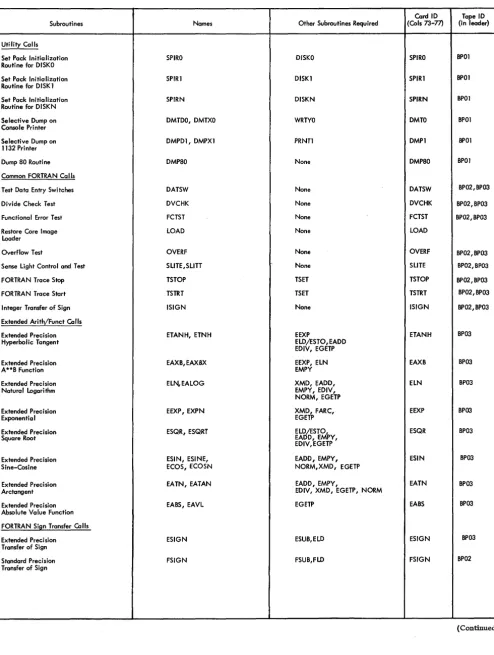
Card Subroutine (CARDO and CARD 1) Errors ••••••••• 17 Console Printer Subroutine (TYPEO and WRTYO) EJTOrs ••• 19 Keyboard Subroutine (TYPEO) Functions •••••••••••• 19 Paper Tape Subroutines (PAPT) •••••••••••••••••• 19 Adding and Removing Subroutines • • • • • • • • • • • • • • •• 19 1130 Subroutine Library Listing • • • • • • • • • • • • • • • • •• 20
UTILITY ROUTINES •••••••••••••••••••••••••• 26 Loading Routines • • • • • • • • • • • • • • • • • • • • • • • • • • • •• 26 Card System Relocating Loader ••••••••••••••••• 26 Card System Core Image Converter • • • • • • • • • • • • • •• 28 Card System Core Image Loader • • • • • • • • • • • • • • • •• 31 Paper Tape System Relocating Loader ••••••••••••• 31 Paper Tape System Core Image Converter. • • • • • • • • •• 31.1 Paper Tape System Core Image Loader ••••••••••••• 31.2 Utility Input/Output Routine ••••••• 0 • • • • • • • • • • • • • 31.2
I/O Character and Record Format •••••••••••••••• 31.2 Control Card Format •••••••••••••••••••••••• 32 User's Exit Option--Card and Paper Tape ••••••••••• 32 I/O Routine EITor Checks ••••••••••••••••••••• 34 Operating Instructions -- Card and Paper Tape •••••••• 34 Dump Routines •••••••••••••••••••••••••••••• 34 Keyboard Routine •••••••••••••••••••••• 0 • • • • • 36
Card Reproducing Routine •••••••••••••••••••••• 37 Console Routine ••••••••••••••••••••••••••••• 37 Disk Pack Initialization Routine (DPIR) •••••••••••••• 38 Construct Paper Tape Routine •••••••••••••••••••• 39 Operating Notes ••••••••••••••••••••••••••• 41
APPENDIX A. CORE MAP •••••••••••••••••••••• 42
APPENDIX B. CORE REQUIREMENTS AND PROGRAM
TIMES ••••••••••••••••••••••••••••••••••• 43
APPENDIX C. SAMPLE PROGRAMS •••••••••••••••• 45
APPENDIX D. 1130 CARD DECK AND PAPER TAPE
IDENTIFICA TION •••• • • • • • • • • • • • • •• 49
APPENDIX E. RELOCATABLE CARD AND PAPER
TAPE FORMATS •••••••••••••••••• 51
APPENDIX F. BINARY CARD •••••••••••••••••••• 54
APPENDIX G. ERROR WAITS AND PROGRAM WAITS •••• 55
APPENDIX H. PAPER TAPE READER ERROR (CHECKSUM) RESTART ••••••••••••••••••••••• 57
APPENDIX I. CONSOLE AND INTERRUPT RESTART
PROCEDURES • • • • • • • • • • • • • • • • • • • •• 59
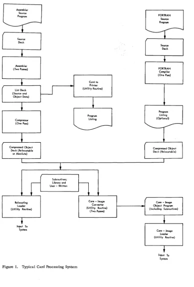
The primary input to the 1130 computing system is from cards or paper tape. The handling of data
Assembler Source Program
Source Deck
Assembler (Two Passes)
List Deck (Source and Object Data)
Compressor (One Pass)
Compressed Object Deck (Relocatable
or Absolute)
Subroutines;
Card to Printer (Utility Routine)
Program Listing
r-
Library and ~User - Written
L - - - . - I
~ ______ -L __ ~ __ ~ r---~---L---~
Relocating Loader (Utility Routine)
+
Input To System
Figure 1. Typical Card Processing System
Care - Image Convertor (Utility Routine)
(Two Passes)
iv
INTRODUCTION
from either source is basically the same. A typical card processing system is shown in Figure 1.
FORTRAN Source Program
Source Deck
FORTRAN Compiler (One Pass)
Program Listing (Optional)
-Compressed Ob jec:t Deck (Relocatable)
Core - Imoge Object Program (Including Subroutines)
Core - Image Loader (Utility Routine)
Input To System
[image:4.615.41.431.150.726.2]The IBM 1130 Assembler, available in both paper tape form and card form, is the medium by which a symbolic source program is converted (assembled) into a machine language program. Mainline pro-grams and subroutines intended for use with the 1800 card/paper tape system can also be assembled with this assembler. The assembler is a two-pass pro-gram. In addition, after the second pass, a com-pressor program must compress the object program before it can be loaded into the CPU for execution. The operation (using the card system) is as follows:
• Pass 1 is initiated by loading the assembler deck, followed by the source progr'am (see Figure 2). During pass 1, the assembler gen-erates a symbol table for use in the second pass. The maximum size of the symbol table and, hence, the maximum number of symbols that can be defined in a program is determined by the size of core storage, thus:
SOURCE PROGRAM DECK
ASSEMBLER DECK
CORE IMAGE LOADER
1130 SYSTEM (PASS 1)
Figure 2. Card Assembler, Pass 1
SOURCE PROGRAM
ASSEMBLER AND COMPRESSOR PROGRAMS
Size of Core Storage (words),
4096 8192
Maximum Number of Symbols in Table
550 1915
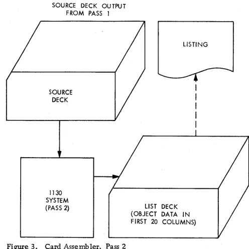
• At the end of the first pass the assembler waits for the user to reload the source program for the second pass. During pass 2, object data in the form of hexadecimal digits and error codes is punched into the first 19 columns of each source card. The resulting deck is a list deck only; it cannot be loaded directly to core stor-age (see Figure 3). If the program will be reassembled later, either another copy of the source deck must be available or columns 21-80 of the list deck must be reproduced to make a new source deck (see Card System Options).
• At the end of the second pass, the list deck can be listed to determine if any errors were de-tected. If a loadable deck is to be made, the compressor program is loaded, followed by the
SOURCE DECK OUTPUT FROM PASS 1
SOURCE DECK
1130 SYSTEM (PASS 2)
Figure 3. Card Assembler, Pass 2
LISTING
LIST DECK (OBJECT DATA IN FIRST 20 COLUMNS)
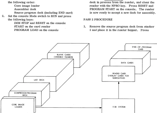
[image:5.612.43.568.205.656.2] [image:5.612.312.560.391.639.2]list deck and a number of blank cards. The data from the list deck is read, converted to compressed binary form, and stored in core storage. After the list deck has passed through the card reader, the compressed data is punched into the blank cards that follow the list deck (see Figure 4).
• The resulting binary object program deck is acceptable as input to the relocating loader or to the core image converter.
CARD ASSEMBLER PROGRAMS
The assembly procedures for pass 1 and pass 2 . are as follows:
PASS 1 PROCEDURE
1. Place cards in the 1442 Card Read Punch in the following order:
Core image loader Assembler deck
Source program deck (including END card) 2. Set the console Mode switch to RUN and press
the following keys:
IMM STOP and RESET on the console ST ART on the card reader
PROGRAM LOAD on the console
LIST DECK
COMPRESSOR PROGRAM DECK
CORE IMAGE LOADER
BLANK CARDS (VARIABLE NUMBER)
Figure 4. Compressor Program Operation
2
The loader feeds the assembler deck into the inside stacker (stacker 1) and the source pro-gram deck into the outside stacker (stacker 2). 3. Press reader START to process the last two
cards (see Card System Options). The card system assembler checks card columns 1-20 on pass 1 and pass 2, immediately after read-ing a source card. At this time these columns should be blank. If a punch is detected the assembler waits with AAAA in the accumulator. 4. To continue the same assembly, remove the
deck from the hopper and clear the reader with the NPRO key. Remove the two ejected cards from the stacker and replace the first card with a duplicate, except for columns 1-20 which must be blank. Place these two cards in proper sequence in front of the unprocessed portion of the deck. Reload this deck in the reader and press reader START. Press PROGRAM START on the console to continue assembly.
5. To start a new assembly, remove the source deck in process from the reader, and clear the reader with the NPRO key. Press RESET and PROGRAM START on the console. The reader is now ready to accept a new deck for assembly.
PASS 2 PROCEDURE
1. Remove the source program deck from stacker 2 and place it in the reader hopper. Press
END - OF - PROGRAM CARD
DATA CARDS
HEADER CARD OVERLAY CARDS FOR
SUBROUTI NES
[image:6.612.41.563.292.669.2]START on the reader. The assembler now completes assembly of the source program, selecting the cards into stacker 1.
2. Press START on the reader to process the last two cards. The output of pass 2 is a list deck.
The list deck can be listed offline, or on-line through the use of a utility routine.
ASSEMBLER CARD FORMATS
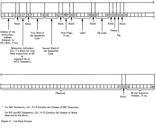
The list deck card format is shown in Figure 5. The.IBM Symbolic Assembly Program Card (Electro No. J76378) format is shown in Figure 6.
Columns 1-16
18-30, 35-71 32-33
73-77 78-80
Form C26 -3629 Page Revised 9-1-66
By TNL N26-0556
Hexadecimal data
IBM card code or EBCDIC Only the indicated charac-ters should be used ID field
Sequence number
The EBCDIC special characters, illustrated on the card, are generated by an IBM 029 Card Punch and the IBM card code special characters by an '1:BM 026 Card Punch. The blocks across the 12 row
of the card are for 80 column interpreters, and those on the 11 row are for 60 column interpreters.
I
I
I
1 1
I
14 5 6 7 8 91 1 112 13 1 116 171819 20 21 1 1I
J2526 271I
13031323334 351 1 1 1I I
:
Instruction; Address Assigned to
First Word of the Assemb led Code * the Label, if any
Relocation Indicators; Col. 7 is Blank for One-Word Instructions or DC
or Exponent for an XFLC Statement.
Second Word of the Assembled
Code
Error F lags I
if any
* For ESC Statements, Col. 9-12 Contains the Number of ESC Characters For SSS and BES Statements, Col. 9-12 Contains the Number of Words Reserved for the Block.
Figure 5. List Deck Format
I
Label Op Code
Tag
80
~--"'"" ,..---..,,/ ID and Sequence Blank Number / if any
[image:7.612.43.542.275.696.2]Form C26-3629 Page Revised 9-1-66
By TNL N26-0556
Ulm
I
WORD'I
WORD 2W
U W
W
t--;;O;:;PE;:;;RA:;;:;N:;;DS;-;A:;;;ND"'R::::EM::-:-A:::::RK~S -~-oll"l'n-"""or---"""!rrTlll-"""!"ttl_~11
10. AND SEO)i
~1!
...
~
[..J
1 ."'.. ...
I
~
I " , . . I . . " . . Ih,j
II-::OP::::ER~ANd:~-=rsT'. 7.AN=~"""U'-=IRE=M+':R=KS=----!...o
...II.--..!..!~
!I
nI :
I D. AND SEO. NO.I
~It ~ 0 000 00 00000000 0 0
Do
0 0 0 0 0 0 0 0COD
000000 0 000000D
0
0 000'J CD 1 2 3 4 • 1 • 10 1112 13 ,. 15 ,. ,. ,. 21 22 23 24 25 21 21 29 30 32 33 35 31 37 31 39 4D 41 42434445 4& 47 4& 49 50 51 52 53 54 55 51 57 51 5110 .,12 831M 65 66 67 ~ 69 70 11
!)~]g 1A1A 1A 1A1A1'A1A \\ \1'~1'~ .~..,..,.~ 01 ;1;1;1;1;1'~1;1'~1IJC~rJUQml1'~1;1[G[~DO~JD
3747516771.,910
I . In E I C D H O L L E8CDHOLL
...
~-'
__::~ ~o
23 CO 23 eB
23 eB 23 eB 23 eB 23 Be 32 eB
:~T:·T· :~T23:·L·T23:" :~';.~LST:LT:LT
012 3\ 2 \
2'~ 2'~
2\ 2'~2'~
2 '\ 2 ¢'0: DO
*
0
2 \ 2 \2 ¢!0 :
DO*
D
~ .. '\ ' .. ' .. " .. 2 2 2~ _ ~~ L \3\3\3\3\3\3\3\3·S'.'S,~3\3\3'S'I·S': \\\\\333
~E ~ 4040 40 40404040 00:,00:, c:.u4°"u4°"u c:.u'l.u\°o:, 00 0"u4'l.u4\4'l.u4'l.u4°"u4\4°'t4<*"<i!~*{@4°,,4'l.u4<*"<i!b* ~.@ V"u·"u':.uo"u444
. ~
~EI ~ 5E5E 5E 5E5E5E5E \\ \5\5\ \\\\ [IJ \5\5\5\5\5\5\5\5( )-.'OOOD5\5\5( )-" , .... \\\\\555 ..:I ~ 6 F 6 F 6 F 6 F 6 F 6 F 6 F
V'l.
'~ 6 \ 6 \ \ '~ '~ '~ 0 [ \ 6 \ 6 '~ 6 '~ 6 '~ 6 \ 6 " 6 \ 6 + ;> = [ ~: : . '.: 6 '~ 6 '~ 6 + ;> = 0U
0
0 '~'~"'~" 6 6 6DiII~
11111111111111 ... \1\1\ \ \ \ \xO
~x7'lox7'lox1\1".1"x7'lox1\1J,?1*00D7'Iox7'lox11,?"*·r: ~x\~x~.\111
.
~~~_~_JI ~
:::: :: ::::::::
~~ ~:~:~ ~~~~ ~~ ~:~:~:~:~:~:~:~:~~~~~~~~:~:~:~~~~~~~~. ~~~:::::
1 2 3 4 6 1 9 10 11 12 13 14 15 16
,1,'
21 2223 24 25 27 21 29 30 32 33 35 36 31 36 3940 41 424~ 44 45 .. 4' .. 4\ 5CI 51 52 53 54 5551 51 58 5960 6162 83 64 8566 61 •• 69 10 11 If.l 7~ 7! 11 ~ 711,.llii~l'l5l'l
• Figure 6. Symbolic Assembly Card
CARD COMPRESSOR PROGRAM
PROCEDURE
The procedure for compression is as follows:
1. Place cards in the reader in the following order: Core image loader
Compressor program deck List deck from pas s 2 Blank cards
2. Set the console Mode switch to RUN and press the following keys:
IMM STOP and RESET on the console ST ART on the card reader
PROGRAM LOAD on the console The list deck is read in by the compressor program and a compressed binary object deck is punched into the blank cards and fed into stacker 2. The list deck and any excess blank cards are fed into stacker 1.
In the event that a card with an assembler error code is detected during compression, ,the system WAITs with 9696 in the .accumulator.
If this error halt occurs, the user can terminate or continue the compression by pressing PROGRAM START (see PACH). The erroneous card is ignored. A new compression can begin after the END card is read.
COMPRESSED DECK FORMAT
Each card in the compressed deck contains up to 54 16 -bit words, excluding the ID (identification) and
4
sequence fields. The cards and their contents are Rhown in Appendix E.
CARD SYSTEM OPTIONS
Card system options include the following:
UNINTERRUPTED ASSEMBLY
• The output from pass 1 of an assembly (in stacker 2) can be placed directly behind the END card to allow the assembler to immediately begin pas s 2. The output of pas s 2 is stored in stacker 1.
CONSECUTIVE ASSEMBLY
• At the end of pass 2, another program can begin assembly immediately. This allows the user to place the first card of the second program immediately after the END card of the first program when the first program is being read and punched in pas s 2.
ERROR DETECTION
• If Console Entry switch 15 is ON before pass 2 begins, the only data punched will be error codes
I
for erroneous statements. This allows a program to be checked for errors during an assembly without requiring the entire source deck to beduplicated for the next assembly. If errors are detected with switch 15 on, only cards containing errors need be reproduced. Columns 18-19 must be blanked.
PACH
• If erroneous source cards were ignored during compression, the compressed object deck can be corrected by patching. The user can also alter an object deck by patching. The card compressor accepts the mnemonic op code PACH followed by corrected hexadecimal source record cards and produces compressed binary object patch cards with a zero checksum.
A patch deck is produced as follows:
1. Set the incomplete object deck aside.
2. Make a patch header card by punching PACH in columns 27-30 of a blank card.
3. Consult the assembler listing for source errors. 4. Punch corrected source cards: enter corrected
data in columns 1-16 as indicated in Figure
5--Form C26-3629 Page Added 9-1-66
By TNL N26-0556
List Deck Format. The remaining card columns can be blank.
5. While under the control of the compressor program, place the PAC H card, corrected source cards, and blank cards in the card reader.
6. Press reader START and PROGRAM START
(PROGRAM LOAD if the compressor is being reloaded).
7. A compressed binary object patch deck is pro-duced by the compressor.
8. Remove the END card from the incomplete object deck set aside in step 1 and place the patch deck behind the object deck.
9. Place the END card behind the patched object deck. The corrected binary object deck is acceptable as input to the relocating loader or to the core image converter.
COMPRESSION OF OVERSIZE DECKS
If the program being compressed is larger than the compressor can store before punching (see Card
System Waits and Error Conditions for Assembler and Compressor), the user may place a number of blank cards in the list deck at some point after the first several hundred cards of the list deck.
When these blank cards are sensed, the com-pressor punches out the portion of the binary object deck accumulated this far. Any remaining blank cards are passed on into stacker 1, and compression begins again when the next card in the list deck is sensed (this procedure may leave some blank cards in the list deck).
If not enough blank cards have been inserted in the list deck to hold the portion that has been read at that point, compression continues when list cards are again sensed; the unpunched portion of the list deck is punched when the next blank cards are sensed.
Note that decks may be compressed together. Batching is allowed with no blanks between decks.
CARD SYSTEM WAITS AND ERROR CONDITIONS FOR ASSEMBLER AND COMPRESSOR
RESTART PROCEDURES
In addition to the errors listed below, there are other WAITS described in Appendix G.
Symbol Table Overflow
• When the symbol table is full, the assembler halts with FOFO in the accumulator. If this occurs, either of two corrective procedures can be used:
1. Divide the program into segments and assemble each segment separately, or 2. Reduce the number of symbols by using
relative addressing. For example, the following sequence of instructions
label Operation F· T
1IIIIlili
25 30 ~~ 35 .co .jS
8.EG I AI L D 1-1- 0 N £, ,
,
IS7 0 1-1- 8.u {: £,1? , ,
L /)
1-1- H F 0
,
,A 1-1- B U F 2 , ,
lsr a 1-1- BIU F,3, , , 1-1- , , ,
0 N£ 0 C ... 1- l - I, I I I
/3,U F E:R D C
:}::':Ol
•
,H F,O D C
'::{;/'FO
I IR.uF 2- D C ~r~~~~~ 0 ,
8 lIF :3 0 c ~~~~~~~j~~ 0 I I I
I ,
can also be written
label Operation
: : 111111:11135 .jS
~21 _ _ _ 25 ::J::: . .;;;.27 _ _ 3;;;;.0
~LCJ.t;j
'"
L t> :;:::::8,(;c
0 N. ,, S TO f:::::, /Jd?t
c
0 N+,'I , I 1. i -'- L f)
- -
::::{8,6
c
0 Nf,2/I
--
B,G C 0 N+
3,
I L S 7 0 I--~ BIG C 0 N +,4 I I, .,.,."",1-l -
.
/3GC O,N D c I
.
,
D C ::::::::::1-1- 0 I I
I D C 1-1- /.~o
.
II I DC 1--1-- 0 I I
DC 1--1- 10.
.
I I I 1 " - ' - - Iand eliminate four symbols.
Oversize Program
If the compressor encounters more list deck cards than it can handle before blank cards are sensed, the compressor waits with FFFF in the accumulator. The following procedure is used to restart.
1. Remove the unprocessed portion of the list deck. 2. Clear the reader with the NPRO key.
3. Place the two non-processed cards ahead of the remaining portion of the list deck.
4. Insert blank cards into the reader, followed by the remainder of the list deck.
5. Press reader START.
The compressor then punches binary cards for the part of the list deck that has been read and passes the remaining blank cards. When the first card of the unprocessed portion of the list deck is sensed, the compression continues. This process can be repeated as necessary to compress the entire program.
Read Error
If an error occurs during reading the reader stops in a not-ready status.
1. Remove the remainder of the deck from the hopper.
2. Press the NPRO key.
3. Place the two non-processed cards ahead of the unused portion of the deck.
4. Reload the deck in the hopper.
5. Press reader START.
Assembler and Compressor Programs 5
Punch Error
If an error occurs during punching the reader stops in a not-ready status.
1. Remove the deck.
2. Pres s the NPRO key to clear the two cards remaining in the reader.
3. Duplicate the first card, except for columns 1-20 which must be blank, and discard the erroneously punched card.
4. Place the two cards ahead of the unused portion of the deck.
5. Reload the deck in the hopp'er.
6. Press reader START.
The Punch Error procedure applies to the assembler only. For the compressor:
1. Press NPRO.
2. Discard the mispunched card.
3. Insert more blank cards in the hopper.
4. Press reader START.
Errors occurring on the last card of a deck are not noted until after reader START is pressed.
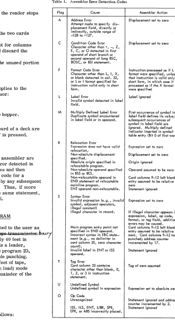
ERROR DETECTION CODES
Error detection codes for the 1130 assembler are listed in Table 1. For the first error detected in each statement the assembler stores and then punches the code in column 18; the code for a
second error is stored, overlayed by any subsequent errors, and punched in column 19. Thus, if more than two errors are detected in the same statement, only the first and last are indicated.
PAPER TAPE ASSEMBLER PROGRAM
The paper tape assembler is supplied to the user as self-loading p...'PTC/g ~eFf8Fat8Q t~Q traRsm-is-sion bltl{;')l
"'OOde/8 elul:AR:QI) tape, approximately 40 feet in length. The beginning of the tape is a leader, several feet long, that contains the program ID, preceded and followed by delete code punching. Following this leader are several feet of tape, punched in the IPL (initial program load) mode (i. e., four bits per frame); the remainder of the tape is binary.
ASSEMBLY PROCEDURES
Loading Assembler Program
The assembler tape is loaded as follows:
6
Table 1. Assembler Error Detection Codes
Flag Cause
A Address Error
Attempt made to specify dis-placement field, directly or indirectly, outside range of
-128 to +127.
C Condition Code Error Character other than +, -, Z, E, C, or 0 detected in first operand of short branch or second operand of long BSC, BOSC, or BSI statement.
F Format Code Error
Character other than L, I, X, or blank detected in col. 32,
or L or I format specified for instruction valid only in short form.
L Label Error
Invalid symbol detected in label field.
M Multiply Defined Label Error Duplicate symbol encountered in label field or in operand.
R Relocation Error
Expression does not have valid relocation.
Non-absolute displacement specified.
Absolute origin specified in relocatable program.
Non-absolute operand specified in BSS or BES.
Non-relocatable operand in END statement of relocatable mainline program.
ENT operand non-;elocatable.
S Syntax Error
Inva lid expression (e. g., inva lid symbol, adjacent operators, i IIega I constant)
Illegal character in record.
Main program entry point not specified in END operand. Incorrect syntax in EBC state-. ment (estate-.gstate-., no delimiter in
card column 35, zero character count) •
Invalid label in ENT or ISS operand.
T Tag Error
Card column 33 contains character other than blank, 0, 1, 2, or 3 in instruction statement.
U Undefined Symbol
Undefined symbol in expression 0 Op Code
Unrecognized
ISS, ILS, ENT, LlBR, SPR, EPR, or ABS incorrectly placed.
Assembler Action
Displacement set to zero
Displacement set to zero
Instruction processed as if L format were specified, unless that instruction is valid only in short form, in which case it is processed as if the X format were specified
Label ignored
First occurrence of symbol in label field defines its value; subsequent occurrences of symbol in label field are ignored. Multiply defined indicator inserted in symbol table entry (Bit 0 of first word).
Expression set to zero
Displacement set to zero
Origin ignored
Operand assumed to be zero
Card columns 9-12 left blank; entry assumed to be relative zero
Statement ignored
Expression set to zero
If illegal character appears in expression, label, op code, format, or tag field, additional errors may be caused. Card columns 9-12 left blank; entry assumed to be relative zero • Card columns 9-12 not punched; address counter incremented by 17.
Statement ignored
Tag of zero assumed
Expression set to absolute zero
[image:11.612.190.541.56.707.2]1. Set the console Mode switch to RUN; press IMM STOP and RESET on the console. 2. Place the tape in the reader so that the read
starwheels are over one of the frames of
delete code in the leader beyond the program ID. 3. Press PROGRAM LOAD on the console.
Error Check
At the end of the tape are several inches of delete code, which constitute a trailer. When the last data character of the tape is read, the loading routine transfers control to the assembler. The as sembler performs a checksum of the data read in from the tape and, if there is no read error, attempts to read a program tape. In this attempt, the last few inches of delete code are read and the reader stops with the not-ready code showing in the accumulator (see Error Codes).
If, however, the checksum test at the end of loading of the assembler tape is not satisfied, the assembler waits without reading past the trailer. The appearance of the checksum error code in the accumulator, in conjunction with this condition, indicates an error occurred in reacting the assembler. The as sembler should be reloaded. Repeated errors of this type indicate a defective assembler tape or a machine malfunction.
Pass 1 Procedure
In the absence of a checksum error, the program to be assembled can be entered when the assembler halts and the not-ready code shows in the accumu-lator. The input tape should have several inches of delete code leader preceding the first source record and should have a similarly punched trailer.
1. Mount the source program tape on the reader.
2. Press PROGRAM START to begin pass 10f
the assembly.
The tape reader reads the source program tape and waits at the end; the not-ready code is displayed in the accumulator.
Pass 2 Procedure
1. Before beginning pass 2, simultaneously press FEED and DELETE on the paper tape punch to produce a leader punched with the delete code. Release FEED before releasing DELETE to prevent the possibility of producing feed codes (00), which are not valid PTTC/8 characters.
2. Mount the source tape again and press PRO-GRAM START. A list tape is generated during pass 2.
3. At the end of pass 2, simultaneously press FEED and DELETE to produce a few inches of trailer for the list tape that has been generated. Again, release FEED first.
ASSEMBLER TAPE FORMAT
The symbolic program input to the assembler is punched on PTTC/8 tape, one frame per character. The format of the tape records is the same as the card system except for the following:
1. The tape does not contain preceding blanks corresponding to card columns 1-20. 2. The tape does not contain blanks or data
corresponding to card columns 72-80.
3. Trailing blanks need not be punched. Therefore, up to 51 characters (corresponding to card columns 21-71) can appear in the tape record.
Tape records are separated by NL (new line) characters (code DD). The delete character (code 7F) is ignored whenever it is read, but the reader stop character (RS, code OD) causes the program reading the tape to wait and start reading again when PROGRAM START is pressed. The case shift characters (codes OE, 6E) are allowed, but are not considered to occupy a space in the format.
The output from the assembler is a list tape, similar to the input tape, but with 20 frames added to the beginning of each record corresponding to card columns 1-20. The list tape is the input to the compressor program.
PAPER TAPE COMPRESSOR PROGRAM
COMPRESSOR PROCEDURE
The operating instructions for the paper tape com-pressor are the same as those for the assembler with the following exceptions:
• The compressor tape is somewhat shorter than the assembler tape.
• The input tape is the list tape generated during pass 2 of the assembler program.
• The output is a binary tape in standard system relocatable format (although the program may be
absolute). This tape is suitable for input to the relocating loader or core image converter.
• There is no second pass; therefore, the leader for the binary output tape should be punched before mounting the list tape.
• A listing on the Console Printer can be obtained by turning on Console Entry switch 15. Page skipping is implemented by means of a line counter for standard 11-inch-depth paper and is controlled by Console Entry switch 14.
Fifty-eight lines are printed, then eight lines are skipped when switches 14 and 15 are on. The setting of the Console Entry switches can be altered at any time during the compression. A carrier return takes place before the first line is printed.
COMPRESSED TAPE FORMAT
The output from the compressor is a binary tape with records identical, word-for-word, to the corresponding card system cards. (ID and sequence numbers are omitted; refer to Appendix E for tape formats, and to Appendix H for illustration of typical compressed tape record.) Each binary
record is preceded by a one-frame word count that gives the total number of words in the record (not counting the word count). Trailing zeros are de-leted from all non-data records.
At the beginning and end of the tape and between records the delete codes are recognized.
All tapes should contain leaders and trailers of delete code.
8
PAPER TAPE WAITS AND ERROR CONDITIONS FOR ASSEMBLER AND COMPRESSOR
ERROR CODES
The following waits requiring manual intervention-may occur while assembling or compressing:
Accumulator Display
7001 AOOI 9001
9002
FFOO
Cause
Reader not ready during loading Punch not ready
Reader not ready during pas s 1 processing
Reader not ready during pas s 2 processing
Checksum error (incorrect data read during loading)
ERROR CONDITIONS
• A checksum error indicates a defective tape or a machine malfunction in reading the processor tape. If several attempts to read the processor fail, the tape should be replaced. ~9 I\.pf)9aQi&-·H-f6F ghe.GkSY:JJl l:'€starl' pI 8@S8tl1"e.
The IBM 1130 FORTRAN Compiler is a program, supplied by IBM, that translates source program statements into a form suitable for execution on the IBM 1130 Computing System. The translated state-ments are known as the object program. The com-piler detects certain errors in the source program and writes appropriate messages on the console printer or 1132 Printer. The compiler also produces a listing of the source programs and storage alloca-tions. Programs intended for use with the 1800 card/
I
paper tape system can be compiled with this compiler. For 1130 FORTRAN I/O logical unit definitions, the I/O unit numbers are permanently set as des-cribed in Table 2.• Table 2. 1130 FORTRAN I/O Logical Unit Definitions
logica I
Unit Kind of Record Size
Number Device Transmission Allowed
1 Console printer Output only 120
2 1442 Card Read Input/output 80
Punch
3 1132 Printer Output only 1 carriage control + 120
4 1134-1055 Input/output 80, plus max. of
Paper Tape 80 case shifts for
Reader/Punch PTTC/8 code,
plus NL code.
6 Keyboard Input only 80
7 Plotter Output only 120
CARD SYSTEM COMPILER LOADING
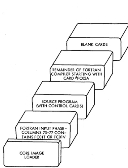
The FORTRAN compiler is divided into two logical parts: an input phase and a series of compilation phases. The loading sequence for compilation is shown in Figure 7.
CARD LOAD INSTRUCTIONS
1. Place the deck in the 1442 Card Read Punch in the order shown in Figure 7. (Sufficient blank cards should be placed behind the compiler to allow object deck punching. )
2. Press IMM STOP and RESET on the console.
3. Press START on the 1442.
4. Press PROGRAM LOAD on the console.
FORTRAN INPUT PHASE-COLUMNS 73-77 CON-TAINS FCOIT OR FCOIV
CORE IMAGE LOADER
BLANK CARDS
Form C26-3629 Page Revised 9-1-66
By TNL N26-0556
FORTRAN
Figure 7. Loading Sequence for FORTRAN Compilation
The source deck and the relocatable object program deck will be in the outside stacker (stacker 2) when the compilation is completed.
CARD LOAD ERRORS
In addition to the card load errors described below, there are other program WAITS described under Core Image Loader in Appendix G.
Program Loop
If the program loops after any phase of the com-piler has been read in, check the system I/O units for a "not ready" condition.
1442 Errors
Read Errors. Clear the 1442 with the NPRO key. Place the two nonprocessed cards in front of the unprocessed portion of the deck in the reader hopper and press reader START. If the error occurs during
[image:14.617.317.524.86.359.2] [image:14.617.41.290.298.470.2]Form C26-3629 Page Revised 9-1-66
By TNL N26-0556
the core image loader program load it is also neces-sary to press PROGRAM START.
Feed Errors. Feed check errors should be treated in the same manner as read errors. Observe whether one 0r two cards are passed out on NPRO, and place them in front of the unprocessed portion of the deck.
Punch Errors. Clear the 1442 with the NPRO key, discard the erroneously punched card, replace the blank cards in the hopper, and press reader START to continue.
CONTROL RECORD OPTIONS
Option Control Cards
When using the FORTRAN compiler, the user can specify certain options by means of control cards. Control cards must precede the source program. They need not be in any specific order, but each must have an asterisk in column 1. The control record name can appear free-form: any place between columns 2 and 72, inclusive. Comments are not per-mitted on these control cards.
The *IOCS, *NAME, and *SAVE LOADER cards can be used only in mainline programs; the others may be used in both mainline programs and sub-routines. Every card having an asterisk in column 1 will be listed on the output device assigned by the program.
Any unrecognizable FORTRAN control record is considered to be a comments record and the option is not performed. No error occurs during compila-tion.
The effect of each control card on compilation is described in the paragraphs that follow.
*IOCS (CARD. TYPEWRITER, KEYBOARD, 1132 PRINTER, PAPER TAPE, PLOTTER) This card must be used to specify any
1/0
device required for execution of the program; however, only the devices required should be included. Because the *IOCS card can appear only in the mainline program, it must in-clude all the I/O devices used by all FORTRAN sub-programs that will be called. The device names must be in parentheses with a comma between each name.Assembly language subroutines referenced by a FORTRAN mainline program can use any I/O sub-routines for any device that is not mentioned in *IOCS and that is not on the same interrupt level as a device in *IOCS. Otherwise, the subprograms must use FORTRAN I/O routines (CARDZ, PAPTZ, PRNTZ, WRTYZ, TYPEZ, PLOTX) •
• 10
*LIST SOURCE PROGRAM The source program is listed as it is read in.
*LIST SUBPROGRAM NAMES The names of all subprograms (including EXTERNAL subprograms) called directly by the compiled program are listed.
*LIST SYMBOL TABLE The following are listed:
• Variable names and their relative addresses
• Statement numbers and their relative addresses
• Statement function names and their relative addresses
• Constants and their relative addresses
*LIST ALL The source program, subprogram names, and symbol table are listed. If this card is used, the other *LIST control cards are not required.
*EXTENDED PRECISION Variables and real
con-stants are stored in three words instead of two, and the compiler generates linkage to extended precision routines. When this control card is used, the program does not conform to the ASA basic FOR TRAN standard for data storage; it may require modification in order to be used with other FORTRAN systems.
*ONE WORD INTEGERS Integer variables are allocated one word of storage rather than the same allocation used for real variables. Whether this control card is used or not, integer constants are always contained in one word. When this control card is used, the program does not conform to the ASA basic FORTRAN standard for data storage; it may require modification in order to be used with other FORTRAN systems.
*NAME XXXXX The program name represented by XXXXX is punched in columns 73-77 of the object deck (columns 78-80 are sequence numbered). This control card is used only on mainline programs since subprogram names are automatically taken from the FUNCTION or SUBROUTINE statement and punched into the deck.
This Control record does not cause any punching in the object paper tape but does give a listable name to the mainline program.
*ARITHMETIC TRACE The compiler generates
linkage to trace routines whenever a value is assigned to a variable on the left of an equal sign. If Console Entry switch 15 is on at execution time, the trace
printout routine prints the value of the assigned variable (see Optional Tracing).
*TRANSFER TRACE. The compiler generates linkage to trace routines whenever an IF statement or computed GO TO statement is encountered. If Console Entry switch 15 is on at execution time, the trace printout routine prints the value of the IF expression or the value of the computed GO TO index (see Optional Tracing).
If tracing is requested, an *IOCS control card must also be present to indicate that either the console printer or the 1132 Printer is needed. If
both the console printer and the 1132 Printer are indicated in the *IOCS card, the 1132 Printer is used for tracing.
The traced value for the assignment of a variable on the left of an equal sign of an arithmetic statement is printed with one leading asterisk. For the expres-sion of an IF statement, the traced value is printed with two leading asterisks. The traced value for the index of a computed GO TO statement is printed witli three leading asterisks.
*SAVE LOADER. If this control card is used, the source statement CALL LOAD can be included in the FORTRAN program. The loader will not be overlaid by variables in storage, and the CALL LOAD statements will cause the next program in the reader to be loaded, if it is in core image form. The CALL LOAD feature can be used only in card programs that have been converted to core image. This feature is not available in the paper tape system.
I
** Header Information If the 1132 Printer is used for output, the infor!p.ation contained in card col-umns 3-72 is printed at the top of each page printed out during compilation.Operating Notes - *LIST Control Cards
I
A constant in a STOP or PAUSE statement is treated as a hexadecimal number. This number and its decimal eqUivalent appear in the list of constants.Variables and constants that require more than one word of storage have the address of the word nearest the zero address of the machine. In the
case of arrays, the given address refers to the ad-dressed word of the first element. In the case of a two-or three-word integer, the integer value is contained in the addressed word. The first variable listed might not be addressed at 0000 because room may be required for generated temporary storage locations.
Form C26-3629 Page Revised 9-1-66
By TNL N26-0SS6
The relative address for variables not in COM-MoN would be the actual address if the program started at storage location zero. The relative ad-dress for variables in COMMON would be the actual address if the machine had 32K storage. The relo-cating loader or core image converter makes any necessary adjustments. Variables in COMMON are adjusted to reside in the high-order core location of the machine being used (e. g., first COMMON variable will be loaded to 8191 on an 8K machine).
The actual storage location at which loading begins is variable and can be obtained as follows:
• When the relocating loader is used with a FOR-TRAN mainline deck that uses the *SA VE LOADER control card, relative address zero of the mainline program is at absolute location 027C.
This configuration can be used to debug the program up to, but .not including, any CALL LOAD statements. The CALL LOAD statement can be executed only with the core image loader.
• When the relocating loader is used without the *SAVE LOADER control card, relative address zero must be computed as follows:
If the number of words for variables not in COMMON is equal to or greater than 454, relative address zero is at absolute location 00B6.
If the number of words for variables not in COMMON is less than 454, relative address zero is at absolute location 027C, minus the number of words for variables.
• When the core image loader is used with a FOR-TRAN mainline deck that uses the *SA VE LOADER control card, relative address zero of the main-line is at absolute location 00D6.
• When the core image loader is used without the *SAVE LOADER control card, relative address zero must be computed as follows:
If the number of words for variables not in COMMON is equal to or greater than 32, relative address zero is at absolute location 00B6.
If the number of words for variables not in COMMON is less than 32, relative address zero is at absolute location 00D6, minus the number of words for variables.
Form C26-3629 Page Revised 9-1-66
By TNL N26-0556
1800 SYSTEM CONTROL RECORD OPTIONS
The following control records are valid only for programs that are to be executed on an 1800 System.
*IOCS (1443 PRINTER, MAGNETIC TAPE) The 1443 PRINTER or MAGNETIC TAPE options must be specified in an 10CS record for programs requiring those devices. Programs using either the 1443 PRINTER or MAGNETIC TAPE options can be executed only on an 1800 System.
I
*MULTIPLE DEVICE or *MULTIPLE DEVICE(CARD, TYPEWRITER, KEYBOARD) This control
record, which is valid for 1800 System programs only, indicates that more than one of the same type I/O device i~ attached to the system (for the pur-pose of this control record a 1053 and an 1816 are considered to be the same type).
The multiple device control card causes the com-piler to generate linkage to the multiple device
FORTRAN I/O subroutines. If a multiple device control card is not present in a mainline program, linkage to the single device (type Z) subroutines will be generated. A multiple device control card must also be present in any subprogram requesting a device specified in the mainline *IOCS control card.
Without the parentheses, the multiple device control card causes the 0 version (no error parameter) of the CARD, WRTY, and TYPE subroutines to be selected. This selection is accomplished via an A version of these subroutines.
With the parentheses, the multiple device control card signifies that multiple devices are being used and the 1 version (error parameter) of the subroutines are requested. CARD, TYPEWRITER, and KEY-BOARD are the only names which will have any effect when used within the parentheses of this control card.
Table 2.11ists the subroutine options.
OPTIONAL TRACING
The user can elect to trace only selected parts of the program by placing statements in the source program logic flow to start and stop tracing. This is done by executing a CALL to either subroutine:
12
CALL TSTOP (to stop tracing) CALL TSTRT (to start tracing)
• Table 2-1. Subroutine Called for I/O Device in *IOCS
SUBROUTINE CALLED
I/O Device No Multiple Device *Multiple Device *Multiple Device (with units Specified
Control Card Control Card named) in *IOCS
Control Card
Card CARDZ CARDO via CARD 1 (CARDO
CARDA via CARDA if called but not specified in parentheses)
Magnetic MAGTZ MAGT MAGT
Tape
Typewriter TYPEZ TYPEO via TYPE1 (TYPEO TYPEA via TYPEA if
called but not specified in parentheses)
Keyboard WRTYZ WRTYO via WRTY1 (WRTYO
WRTYA via WRTYA if called but not specified in parentheses)
1443 PRNTZ PRNTl PRNT1
Printer
Paper PAPTZ PAPTl PAPTl
T __
I'"·'
PlotterThus, tracing occurs only if:
• The trace control records were compiled with the source program.
• Console Entry switch 15 is on (can be turned off at any time).
• A CALL TSTOP has not been executed, or a CALL TSTRT has been executed since the last CALL TSTOP.
FORTRAN PRINTOUTS
Compilation Messages
Near the end of the compilation, core usage infor-mation and the features supported (control cards in deck) are printed out as follows:
FEA 'FURES SUPPORTED EXTENDED PRECISION ONE WORD INTEGERS TRANSFER TRACE ARITHMETIC TRACE IOCS
SAVE LOADER
CORE REQUIREMENTS FOR XXXXX
COMMON YYYYYVARIABLES YYYYY PROGRAM YYYYY
where XXXXX is the name of the program designated in the *NAME control record or in the SUBROUTINE or FUNCTION statement, and YYYYY is the number of words allocated for the specified parts of the
I
program Unreferenced statements are considered as possible errors and listed unconditionally.Compilation Error Messages
During compilation, a check is made to determine if certain errors have occurred. If one or more of these errors is detected, the error indications are
Form C26 -3629 Page Added 9-1-66 By TNL N26-0556
printed at the conclusion of compilation and no object program is punched. Only one error is detected for each statement. In addition, because of the interaction of error conditions, the occurrence of some errors might prevent the detection of others until the detected errors are corrected.
The error message appears in the follOwing format:
xxxxx
+ YYY ERROR TYPE AAwhere XXXXX is the last encountered valid state-ment number, YYY is the count of statestate-ments from statement XXXXX, and AA is the error code. Declarative statements are not counted unless they contain errors. Statement numbers on declarative statements are ignored.
Error Code Definitions
1. Non-numeric character in statement number 2. More than five continuation cards, or a
tinuation card encountered in an invalid posi-tion in the program
3. END statement missing
4. Undeterminable, misspelled, or incorrectly formed statement
5. Statement out of sequence
6. Statement following transfer statement or STOP statement does not have statement number 7. Name longer than five characters, or name not
starting with an alphabetic character
8. Incorrect or missing subscript within dimension information (DIMENSION, COMMON, or type) 9. Duplicate statement number
10. Syntax: error in COMMON statement 11. Duplicate name in COMMON
12. Syntax: error in FUNCTION or SUBROUTINE statement
13. Formal parameter (dummy argument) appears in COMMON
14. Name appears twice as a formal parameter in the argument list of a SUBROUTINE or FUNC-TION statement
15. *IOCS control record in a subprogram 16. Syntax: error in DIMENSION statement 17. Subprogram name in DIMENSION statement 18. Name dimensioned more than once, or not
dimensioned on first appearance of name 19. Syntax: error in REAL, INTEGER, or
EXTER-NAL statement
20. Subprogram name in REAL or INTEGER statement
21. Name in EXTERNAL statement that is also in COMMON or DIMENSION statement
22. IFIX or FLOAT in EXTERNAL statement 23. Invalid real constant
24. Invalid integer constant
25. More than 15 names, or duplicate names, in statement function argument list
26. Right parenthesis missing from a subscript expression
27. Syntax: error in FORMAT statement
28. FORMAT statement without statement number 29. Field width specification greater than 145 30. In a FORMAT statement specifying E or F
conversion, w greater than 127, d greater than 31, or d greater than w
31. Subscript error in EQUIVALENCE statement
32. Subscripted variable in a statement function 33. Incorrectly formed subscript expression 34. Undefined variable in subscript expression 35. Number of subscripts in a subscript expression
does not agree with the dimension information 36. Invalid arithmetic statement or variable; or,
in a FUNCTION subprogram, the left side of an arithmetic statement is a dummy argument or is in COMMON
37. Syntax error in IF statement 38. Invalid expression in IF statement
39. Syntax: error or invalid simple argument in CALL statement
40. Invalid expreSSion in CALL statement
41. Invalid expression to the left of an equal sign in a statement function
42. Invalid expression to the right of an equal sign in a statement function
43. If an IF, GOTO, or DO statement, a statement number is miSSing, invalid, incorrectly placed, or is the number of a FORMAT statement 44. Syntax error in READ or WRITE statement 45. *IOCS card missing with a READ or WRITE
statement (mainline program only)
46. FORMAT statement number missing or incorrect in a READ or WRITE statement
47. Syntax error in input/output list or an invalid list element; or, in a FUNCTION subprogram, an input list element is a dummy argument or is in COMMON
48. Syntax error in GOTO statement
49. Index of a computed GOTO missing, invalid, or not preceded by a comma
50. *TRANSFER TRACE or *ARITHMETIC TRACE control record, but no *IOCS control record in a mainline program
51. Incorrect nesting of DO statements, or the terminal statement of the associated DO state-ment is a GOTO, IF, RETURN, FORMAT, STOP, PAUSE, or DO statement
52. More than 25 nested DO statements 53. Syntax: error in DO statement 54. Initial value in DO statement is zero
55. In a FUNCTION subprogram, the index of DO is a dummy argument or in COMMON
56. Syntax error in BACKSPACE statement (1800 only)
57. Syntax error in REWIND statement (1800 only) 58. Syntax error in END FILE statement (1800 only) 59. Syntax error in STOP statement
60. Syntax error in PAUSE statement
61. Integer constant in STOP or PAUSE statement greater than 9999
62. Last executable statement before END statement is not a STOP, GOTO, IF, or RETURN statement 63. Statement contains more than 15 different
sub-script expressions
64. Statement too long to be scanned due to compiler expansion of subscript expressions or compiler addition of generated temporary storage loca-tions
65. *All variables undefined in an EQUIVALENCE list
66. *Variable made equivalent to an element of an array in such a manner as to cause the array
to extend beyond the origin of ' the COMMON area 67. *Two variables or array elements in COMMON
are equated, or the relative locations of two variables or array elements are assigned more than once (directly or indirectly)
68. Syntax error in EQUIVALENCE statement, or an illegal variable name in an EQUIVALENCE list
69. Subprogram does not contain a RETURN state-ment, or a mainline program contains a RETURN statement
*The detection of a code 65, 66, or 67 error blocks any subsequent error with one of these three codes.
In addition, undefined variables are listed by name at the end of compilation. A variable is not defined unless it is on the left side of an assignment statement, is in the list of a READ statement, is an index variable of a DO statement, is in COMMON, is a formal parameter of a subprogram, or is
equivalent to a defined variable. Undefined variables inhibit the output of the object program.
Undefined variables appearing only in subscript expressions generate error code 34, and are not listed here.
If the output of the object program has been inhibited, the following message is printed:
OUTPUT HAS BEEN SUPPRESSED
If an overflow condition results during compilation, the message,
PROGRAM LENGTH EXCEEDS CAPACITY
is printed.
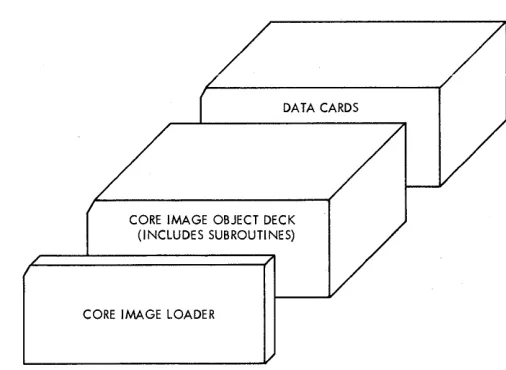
OBJECT DECK LOADING PROCEDURES
After an object deck has been punched, it can be left in relocatable form or converted to core image form. Figure 8 shows the loading sequence for an object program in relocatable form; Figure 9 shows the loading sequence for an object program in core image form.
The subroutine library might have been divided into standard and extended preCision decks. If this is the case, the preCision deck that corresponds to the compilation precision should be used. If trace control cards were included at compilation time, Console Entry switch 15 must be turned on whenever the trace printout is desired.
14
DATA CARDS
SUBROUTINE LIBRARY
SUBPROGRAMS PREVIOUSLY ASSEMBLED OR COMPILED
OBJECT PROGRAM DECK
RELOCA TI NG lOADER
Figure 8. Loading Sequence for Object Program in Relocatable Form
/
DATA CARDS
CORE IMAGE OBJECT DECK (I NCLUDES SUBROUTI NES)
CORE IMAGE LOADER
/1
Figure 9. Loading Sequence for Object Program in Core Image Form
CARD LOAD INSTRUCTIONS
The object program operating procedure is as follows:
1. Place the deck in the 1442 Card Read Punch. 2, Press IMM STOP and RESET on the console. 3. Press START on the 1442.
4. Press PROGRAM LOAD on the console.
[image:20.612.311.558.50.274.2] [image:20.612.302.555.314.499.2]sub-routine library deck. The library deck should be run out with the NPRO key before blank cards are placed in the reader. Ready the reader and press PROGRAM START to continue.
To restart a FORTRAN program that has been loaded in relocatable form, the procedure is as follows:
1. Set the Mode switch to LOAD.
2. Set 0198 into the Console Entry switches. 3. Press LOAD IAR.
4. Set the Mode switch to DISP. 5. Press PROGRAM START.
6. Set contents of the storage buffer register into the Console Entry switches.
7. Set the Mode switch to LOAD. 8. Press LOAD IAR.
9. Set the Mode switch to RUN.
10. Ready any I/O devices used with data repositioned for the first READ statement. 11. Press PROGRAM START.
The above procedure may not work if the program was stopped during an I/O operation. To continue, reload the object deck.
KEYBOARD INPUT OF DATA RECORDS
Data records of up to 80 characters can be read from the keyboard by a FORTRAN READ statement. Data values must be right-justified in their respective fields.
Keyboard .operation
If it is desirable to key in less than 80 characters, the EOF key can be pressed to stop transmittal. Also, the ERASE FIELD or BACKSPACE key can be pressed to restart the record transmittal if an error is detected while entering data. If the keyboard appears to be locked up, press REST KB to restore the keyboard. The correct case shift must be se-lected before data is entered.
Buffer Status After Keyboard Input
When the EOF key is pressed prior to completing a full buffer load of 80 characters, blanks are inserted in the remainder of the buffer. If more data is necessary to satisfy the list items, the re-maining numeric fields (I, E, or F) are stored in core as zeros and remaining alphameric fields (A or H) are stored as blanks. Processing is con-tinuous and no errors result from the above condi-tion.
Form C26-3629 Page Revised 9-1-66
By TNL N26-0556
OBJECT PROGRAM DATA RECORD FORMAT
Data records of up to 80 EBCDIC characters in PTTC/8 code can be read or written by the FOR-TRAN object programs. The delete and new-line codes are recognized. Delete codes and case shifts are not included in the count of characters. If a new-line code is encountered before the 80th char-acter is read, the record is terminated. If the 80th character is not a new-line code, the 81st character is read and assumed to/be a neW-line code. A new-line code is punched at the end of each output record.
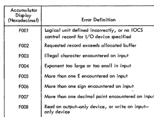
FORTRAN I/O ERRORS
If input/output errors are detected during execution, the program stops and cannot be continued. The error is indicated by a display in the accumulator. The error displays and their meanings are listed in Table 3.
When the output field is too small to contain the number, the field is filled with asterisks and execution is continued.
The input/output routines used by FORTRAN (PAPTZ, CARDZ, PRNTZ, WRTYZ, TYPEZ) wait on any I/O device error or device not in a ready condition. When the devices are ready, press PROGRAM START to execute the I/O operation.
Error detection in functional and arithmetic subroutines is possible by the use of source program statements. Refer to "FORTRAN Machine and Pro-gram Indicator Tests" in the manual, ruM 1130 FORTRAN Language (Form C26-5933).
Table 3. FORTRAN I/O Enor Indications
Accumu lator Display
{Hexadecimal} Error Definition
FOOl Logical unit defined incorrectly, or no IOCS control record for I/O device specified
FOO2 Requested record exceeds allocated buffer
FOO3 Illegal character encountered on input
FOO4 Exponent too large or too small in input
FOO5 More than one E encountered on input
FOO6 More than one sign encountered on input
FOO7 More than one decilmal point encountered on input
FOOS Read on output~nly device, or write on input-only device
[image:21.617.47.281.142.300.2] [image:21.617.319.571.523.713.2]Form C26-3629 Page Revised 9-1-66
By TNL N26-0SS6
PAPER TAPE SYSTEM COMPILER LOADING
In the paper tape FORTRAN system, the compiler loading sequence should be as follows:
1. Core image loader 2. FORTRAN input phase 3. Sourceprogram
4. Balance of FORTRAN compiler
COMPILER LOAD INSTRUCTIONS
The following procedure should be followed to initiate the program load:
1. Set the Mode switch to RUN and press IMM STOP and RESET on the console.
2. Ready the paper tape reader. Place the tape in the reader, positioning the tape so that the read starwheels are over one of the frames of delete code in the leader beyond the program ID. 3. Ready the paper tape punch. Create a leader
of delete codes by simultaneously preSSing DELETE and FEED. Reiease FEED beiore releasing DELETE.
4. Press PROGRAM LOAD on the console.
Any tape information can be loaded from separate strips of tape (i. e., control records, source state-ments). Each segment must be preceded by and followed by two or more inches of tape delete char-acters.
Program printouts and program options are the same as described in the preceding sections on the card system.
PAPER TAPE LOAD ERRORS
In addition to the paper tape load errors described below, there are other program WAITs described under C ore Image Loader in Appendix G.
Character other Than Delete Read After Source Tape
Phase 2· of the FOR TRAN compiler is preceded by two records, each containing a single dollar sign character. Detection of the first of these records causes the compiler to pass the second record
. 1 6
without processing and start loading phase 2 of the compiler when the first valid record containing program data is read.
If any character (other than DELETE) is read between the last character of the source tape (always a new line character) and the first dollar sign record of the second FORTRAN compiler tape, the compiler will not load correctly. A checksum error will occur. If a listing is being made and this error occurs, a dollar sign appears as the last character on the last printed line. In order to prevent this error from occurring, the user should be certain that the end of the last source tape is trimmed so that only DELETE characters are read. Do not open the read head while reading the trailer on this tape, as a NON-DELETE character can be
read.
Parity Error
A parity error during reading will cause the system to WAIT at 01E2 during phase 01 W (1132 Printer output) and at OIFA during phase OlU (Console Printer output). The WAIT address is displayed in the storage address register.
To continue, back the tape one frame and press PROGRAM START.
Reader Not Ready
A reader not-ready condition will cause the system to WAIT at 0190 during phase 01 W (1132 Printer output) and at 0194 during phase 01 U (Console Printer output). The WAIT address is displayed in the storage address register.
To continue, clear the cause of the not-ready condition; check that the tape tension switch is closed, check that the tape is loaded properly and is feeding freely. When the tape reader is ready, press PROGRAM START.
Punch Not Ready
A punch not ready condition will cause the system to WAIT with 050A in the storage address register. To continue, clear the cause of the not-ready condition; check that