IJEDR1401152
International Journal of Engineering Development and Research (www.ijedr.org)1
Simulation and Analysis of AC-AC Converter
With Improved Power Quality
1
Srujal R. Patel,
2Md Aftab Alam,
3Nigam K. Prajapati
1 M.Tech Scholar, 2Assistant professor, 3 Assistant Professor1,2Department of Electrical Engineering, UVPCE, Ganpat University, Kherva, India 3
Department of Electrical Engineering, HCET, Sidhpur, GTU, India
1[email protected], 2[email protected], 3[email protected]
_______________________________________________________________________________________________________ Abstract— AC to AC power converters are static systems using solid-state switching devices that directly convert ac power of a given frequency to ac power of some desired frequency. They are used to link ac power systems of different frequencies, to provide variable power frequency supplies for ac motor drives, and to generate constant frequency power from the output of variable-speed ac generators. AC/AC converters can be categorized into 1) Converters with a DC-link 2) Cycloconverters 3) Hybrid Matrix Converters 4) Matrix Converters. This paper includes the Study & Simulation of AC to AC converter with DC link subsequently the hardware design of single phase AC to AC converter, the topology comprises double power conversions viz. AC to DC and DC to AC conversion. Also, Power topology is simulated in PSIM 9.0 with PWM Generation using PIC microcontroller is discussed.
Keywords - AC/AC Converter, SPWM (Sine Pulse Width Modulation). Index Terms—Component, formatting, style, styling, insert.
I.INTRODUCTION
Today voltage and current source inverter are widely used in electrical motor drives. The DC voltage or current are usually obtained by using rectifiers with phase control and line commutation converter
Figure 1 (a) PSIM Simulation of 1-Phase Uncontrolled Rectifier
Figure 1(b) Input Current Waveform
The most important disadvantages of classical rectifiers are: low order current harmonics generation on the AC line, lagging displacement factor establishment to the utility grid that in its turn consume an important amount of reactive power, unidirectional power transmission and large DC link filter [1, 2, and 3]. Fig.1 (a) and (b) shows the PSIM simulation and waveform of uncontrolled rectifier, in which low order current harmonics generation on the AC line.
Besides, new limit has been applied by standards such as IEEE519- 1992 and IEC 61000-3-2/IEC 6100-3-4 that indicate the current harmonic limits of power electronic converters [4].to overcome these problems in past few years PWM rectifiers are used with its good capabilities such as power regeneration, low harmonic input current, sinusoidal input current wave form, high total power factor, controlled dc-link voltage, small filter, 4-quadrant operation (bidirectional power transmission), PWM rectifiers become more and more popular in industry application [3, 4].Two types of PWM converters, with a voltage source output and a
0 -100 -200 -300 100 200 300 Vin
IJEDR1401152
International Journal of Engineering Development and Research (www.ijedr.org)842
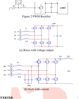
current source output can be used. First of them called a boost rectifier (Fig.2 (a), increases the voltage) operates at fixed DC voltage polarity, and the second, called a buck rectifier (Fig.2 (b), reduces the voltage) operates with fixed DC current flow.
Figure 2 PWM Rectifier
(a) Boost with voltage output
(b) buck with current
II.TOPOLOGYOFAC-ACCONVERTER
Fig. 3 shows a generic three-phase ac–ac converter diagram with active front-end. All key size and weight contributors are shown, including the input filter, dc link (filter and auxiliary circuits), output filter, switching devices, and heat sink, and need to be considered in the high density design. It should be noted that not all of these elements are needed for all topologies, or for all applications. The basic evaluation and comparison approach is formulated similarly to a design optimization problem. Design conditions and constraints are first identified, including performance constraints, such as power quality and EMI standards, and physical conditions and constraints, such as ambient temperature, maximum device junction temperature, and passive component thermal and electrical limits. With a given design objective (in this case, size or weight), key design parameters can then be varied and determined, including switching frequency, control/modulation strategy, minimum L and C values for both energy storage and filter passives, device losses, and cooling system thermal impedances
Figure 3 Typical Topology of 3-phase AC-AC converter
IJEDR1401152
International Journal of Engineering Development and Research (www.ijedr.org)843
III.SIMULATIONRESULTSOFSINGLEPHASEAC-DC-ACCONVERTER
1. Simulation of AC-DC Converter
Figure 4 shows the power circuit of the fully controlled single-phase PWM rectifier in bridge connection, which uses four Switches to produce a controlled dc voltage Vo. Using a bipolar PWM switching strategy, this converter may have two conduction states: (i) Switches S1 and S4 in the on-state and S2 and S3 in the off-state; (ii) Transistors S2 and S3 in the on-state and S1 and S4 in the off-state. In this topology, the output voltage must be higher than the peak value of the ac source voltage, to ensure a proper control of the input
current. When Switches S1 and S4 on. In this case, the inductor voltage is given by,
Therefore, in this condition a reduction of the inductor current is produced. When transistors T2 and T3 on. Here, the inductor voltage has the following expression
This means an increase in the instantaneous value of the input current.
Finally, when transistors T1 and T3 or T2 and T4 are in the on-state. In this case, the input voltage source is short-circuited through inductor L, which yields
Equation implies that the current value will depend on the sign of .
The waveform of the input current is can be controlled by appropriately switching S1–S4 or S2–S3, originating a similar shape to the one shown in Fig.5 for the single-phase boost rectifier.[6]
Figure 4 PSIM schematic diagram of a single phase AC-DC Controlled
0.08 0.085 0.09 0.095 0.1
T i m e (s) 0
-0.5 -1 0.5 1 1.5
IJEDR1401152
International Journal of Engineering Development and Research (www.ijedr.org)844
Figure 5 Results of PWM, Input voltage, Input Current and Output DC voltage waveform 2. Simulation of DC-AC Inverter
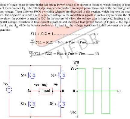
A basic topology of single-phase inverter in the full bridge Power circuit is as shown in Figure 6, which consists of four switching devices, two of them on each leg. The full-bridge inverter can produce an output power twice that of the half-bridge inverter with the same input voltage. Three different PWM switching schemes are discussed in this section, which improve the characteristics of the inverter. The objective is to add a zero sequence voltage to the modulation signals in such a way to ensure the clamping of the devices to either the positive or negative DC. In the process of which the voltage gain is improved, leading to an increased load fundamental voltage, reduction in total current distortion and increased load power factor. In Figure 7, the top devices are assigned to be S
11 and S21 while the bottom devices as S12 and S22, the voltage equations for this converter are as given in the following equations.
... (1)
( ) ... (2)
( ) ... (3)
Figure 6 single phase full bridge inverter topology
0.058 0.06 0.062 0.064 0.066
T i me (s) 0
0.2 0.4 0.6 0.8 1
Vcomp1
0
-200 200
Vin
0 -2 2
Iin
0 0.01 0.02 0.03 0.04 0.05 0.06
Time (s) 0
20 40
IJEDR1401152
International Journal of Engineering Development and Research (www.ijedr.org)845
The voltages
and the output voltages from phases A and B to an arbitrary point n,
the neutral voltage between
point n and the mid-point of the DC source. The switching function of the devices can be approximated by the Fourier series to be equal to ( ) where M is the modulation signal which when compared with the triangular waveform yields the switching pulse. Thus from Equations 1, 2 and 3, the expressions for the modulation signals are obtained as( )
... (4)( ) ... (5)
Equations (4) and (5) give the general expression for the modulation signals for single-phase dc-ac
converters.
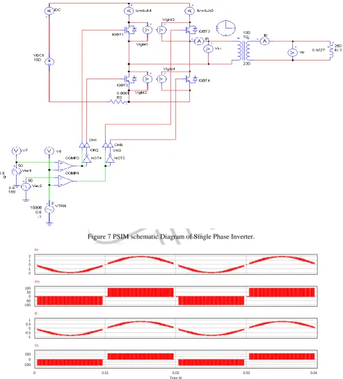
Figure 7 PSIM schematic Diagram of Single Phase Inverter.
Figure 8 Input voltages, Input Current, Output AC voltage waveform
0 -1 -2 1 2
Iin
0 -50 -100 50 100
Vin
0 -0.5 -1 0.5 1
I0
0 0.01 0.02 0.03 0.04
Time (s) 0
-200 200
IJEDR1401152
International Journal of Engineering Development and Research (www.ijedr.org)846
IV.CONCLUSION
An AC/AC converter using PIC 16F777 based control circuit has been implemented. A sine pulse width modulation scheme has been used for the hardware implementation. The converter consists of the two stages first stage AC to DC acts as a rectifier and second DC to AC acts as an inverter. The proposed converter can be further modified for the three phase topology and it can be used in uninterruptible power supply, UPQC and voltage regulator.
V.REFERENCES
[1]“PWM Rectifier with Active Filtering” M. Sc. Mariusz Cichowlas Warsaw University of Technology Faculty of Electrical Engineering Institute of Control and Industrial Electronics Ph.D. Thesis
[2] “Single Phase PWM rectifier” by Ing. Jan Bauer. Department of Electric Drives and Traction, Czech Technical University in Prague, Faculty of Electrical Engineering ,Technická 2 166 27 Praha, Czech Republic
[3]“Implementation of a Single-phase Unipolar Inverter Using DSP TMS320F241” Narong Aphiratsakun, Sanjiva Rao Bhaganagarapu and Kittiphan Techakittiroj Faculty of Engineering, Assumption University Bangkok, Thailand
[4]“Design and Development of Unipolar PWM Switching Pulses for SINGLE PHASE FULL BRIDGE INVERTER APPLICATION” by BAHARUDDIN BIN ISMAIL
[5]“Microcontroller Based Sinusoidal PWM Inverter for Photovoltaic Application”, S. M. Mohaiminul Islam, Gazi Mohammad Sharif School of Engineering and Computer Science, Independent University, Bangladesh
[6]Second Edition Power Electronics Handbook Devices, Circuits and Applications by Muhammad Rashid. Page(s): 195-198 [7]N. Mohan, T. Undeland & W. Robbins (1995) Power Electronics: Converters, Applications and Design, 2nd Edition, Wiley,