(;%
0;533#
DQG
#
(;%
0;533
6;
#;
PP
#
7DSH
#
'ULYH
Copyright
Copyright 1994 by Exabyte Corporation. All rights reserved. This item and the information contained herein are the property of Exabyte Corporation. No part of this document may be reproduced,
transmitted, transcribed, stored in a retrieval system, or translated into any language or computer language in any form or by any means, electronic, mechanical, magnetic, optical, chemical, manual, or otherwise, without the express written permission of Exabyte Corporation, 1685 38th Street, Boulder, Colorado 80301. Disclaimer
Exabyte Corporation makes no representation or warranties with respect to the contents of this document and specifically disclaims any implied warranties of merchantability or fitness for any particular purpose. Further, Exabyte Corporation reserves the right to revise this publication without obligation to notify any person or organization of such revisions or changes.
Trademark Notices
AMP is a trademark of AMP Incorporated. Beckman Industrial is a trademark of Emerson Electric Company. Dale is a registered trademark of Dale Electronics, Inc. dataMate is a registered trademark of Methode Electronics, Inc. EXABYTE is a registered trademark and EXATAPE is a trademark of Exabyte Corporation. Molex is a registered trademark of Molex Incorporated. All other product names are trademarks or registered trademarks of their respective companies.
Revision History
Revision Date Description
000 January 1994 Initial release
Exabyte Corporation 1685 38th Street Boulder, CO 80301 Phone: (303) 442-4333
Safety Standards
The EXB-8200 and EXB-8200SX meet the following safety standards: UL Standard 1950, 1st Edition, Information Technology Equipment; CAN/CSA Standard C22.2 No. 950-M-89, Safety of Information Technology Equipment; and IEC 950/EN60950, Safety of Information Technology Equipment including Electrical Business Equipment (TUV).
FCC Notice
This equipment has been tested and found to comply with the limits for a Class B digital device pursuant to Part 15 of FCC rules. These limits are designed to provide reasonable protection against harmful interference in a residential installation. This equipment generates, uses, and can radiate radio frequency energy and, if not installed and used in accordance with the instructions, may cause interference to radio and television communications. There is no guarantee, however, that interference will not occur in a particular installation. If this equipment does cause interference to radio or television reception, which can be determined by turning the equipment off and on, the user is encouraged to try to correct the interference by one or more of the following measures:
■ Reorient or relocate the receiving antenna.
■ Increase the separation between the equipment and receiver. ■ Connect the equipment into an outlet on a circuit different from
that to which the receiver is connected.
■ Consult the dealer or an experienced radio/TV technician for help and for additional suggestions.
Changes or modifications not expressly approved by Exabyte Corporation could void the user’s authority to operate the equipment. CDC Notice
This digital apparatus does not exceed the Class B limits for radio noise emissions from digital apparatus set out in the Radio Interference Regulation of the Canadian Department of Communication.
VDE Notice
Product Warranty Caution
The EXB-8200 and EXB-8200SX 8mm Cartridge Tape Subsystems (tape drives) are warranted to be free from defects in materials, parts, and workmanship and will conform to the current product specifications upon delivery. For the specific details of your warranty, refer to your sales contract or contact the company from which the tape drive was purchased.
The warranty for the tape drive shall not apply to failures caused by:
■ Physical abuse or use not consistent with the operating instructions or product specifications provided by Exabyte’s personnel or agent for the applicable equipment.
■ Modifications by other than Exabyte’s personnel or agent in any way other than those approved by Exabyte, provided the warranty shall not be voided by the repair or replacement of parts or the attachment of items in the manner described in maintenance or installation instructions provided by Exabyte. ■ Repair by other than Exabyte’s personnel or agent in a manner
contrary to the maintenance instructions provided by Exabyte. ■ Removal of the Exabyte serial number tag.
■ Physical abuse due to improper packaging of returns.
CAUTION
Returning the tape drive in unauthorized packaging may damage the unit and void the warranty. Refer to the packing instructions in this book for information.
Contents
Welcome . . . 7
About This Guide . . . 8
Conventions Used in This Guide . . . 8
For More Information . . . 8
1 Installing the Tape Drive . . . 9
Unpacking the Tape Drive . . . 10
Ensuring ESD Protection . . . 10
Setting the SCSI ID . . . 11
Preparing the Tape Drive for the SCSI Bus . . . 13
Installing the Tape Drive in a PC Drive Bay . . . 16
Performing the Initial Power On . . . 19
2 Operating the Tape Drive . . . 22
Reading the LEDs . . . 22
Selecting Data Cartridges . . . 23
Setting the Write-Protect Switch . . . 25
Loading a Data Cartridge . . . 26
Unloading a Data Cartridge . . . 26
3 Preventive Maintenance . . . 28
Determining When to Clean the Tape Drive . . . 28
Using the 8mm Cleaning Cartridge . . . 29
Caring for Data Cartridges . . . 30
Replacing Data Cartridges . . . 31
4 Packing the Tape Drive . . . 32
Packing the Tape Drive for Shipment . . . 33
Environmental Requirements for Shipment . . . 34
Appendix A Installation Requirements . . . 35
Setting the SCSI ID with DIP Switches . . . 35
Selecting a SCSI Cable . . . 36
SCSI Cable Connector . . . 38
Attaching the Tape Drive to a Frame . . . 38
Chassis Grounding (optional) . . . 40
Power Cable Connector . . . 40
Appendix B Tape Drive Specifications . . . 42
W
elcome
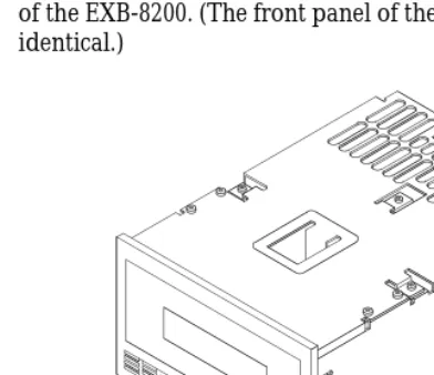
Thank you for selecting the EXABYTE® EXB-8200 or EXB-8200SX 8mm Cartridge Tape Subsystem (tape drive). The EXB-8200 and the EXB-8200SX (shown below) are high-capacity, high-performance, and highly reliable streaming tape drives for PC, super-mini, and mainframe computer systems. Packaged in a standard 5.25-inch form-factor, the EXB-8200 and EXB-8200SX are identical on the outside. The EXB-8200SX supports a high-speed search capability that operates at 75 times the normal tape speed of approximately 0.5 inches per second.
About This Guide
Use this guide as you install and operate the tape drive. In addition to instructions for installation and operation, this guide provides information about selecting and maintaining data cartridges, cleaning the tape drive, and packing the tape drive for shipment.
Conventions Used in This Guide
This guide uses the following conventions to highlight special information:
Note: Notes provide hints or suggestions about the topic or procedure being discussed.
Important
Information in Important boxes will help you
successfully complete a procedure or avoid additional steps in a procedure.
CAUTION
Information in Caution boxes explains how to avoid damaging the tape drive, the data cartridge, other equipment, or data recorded on tape.
For More Information
1
Installing the Tape Drive
This section provides instructions for the following tasks:
■ Unpacking the tape drive and ensuring ESD protection (page 10)
■ Setting the SCSI ID (page 11)
■ Preparing the tape drive for the SCSI bus (page 13)
■ Installing the tape drive in a PC drive bay (page 16) ■ Performing the initial power on (page 19)
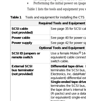
Table 1 lists the tools and equipment you will need.
Required Tools and Equipment
SCSI cable (not provided)
See page 35 for SCSI cable requirements.
Power cable See page 40 for power cable requirements.
Power supply See page 42 for power specifications.
Optional Tools and Equipment
SCSI ID jumpers or remote switch
Use a female Molex® 14-57-3065 (or equivalent) cable connector on the remote switch cable.
External SCSI bus terminator (not provided)
Differential tape drive: If the tape drive terminates the SCSI bus, use a Methode Electronics, Inc. dataMate® DM103-01-0 (or equivalent) differential external terminator. Single-ended tape drive: If the tape drive terminates the SCSI bus, you can remove the tape drive’s internal terminators (R-packs) and use a dataMate DM103-02-0 (or equivalent) single-ended external terminator.
Mounting frame or brackets, four
#6-32 screws, screwdriver
Depending on your installation requirements, can be used to mount the tape drive.
Flat-nose wiring pliers
Can be used to remove the R-packs from a single-ended tape drive. See page 13.
M3-0.5 × 6 mm self-tapping screw
[image:9.612.162.460.195.542.2]Can be used for additional chassis grounding.
Unpacking the Tape Drive
The tape drive’s packaging is designed to protect the tape drive from shock, vibration, moisture, and electrostatic discharge (ESD). Save all original packaging in case you need to repack or ship the tape drive.
CAUTION
If the temperature of the room in which you are unpacking the tape drive differs from the storage location by 15° C (27° F) or more, let the tape drive
acclimate in its packaging to the room environment for at least 12 hours before opening the box. This helps prevent condensation damage to the drive.
After you unpack the tape drive, check the contents of the carton against the packing list and inspect the tape drive for possible damage. If a part is missing or the tape drive is damaged, notify the carrier and your vendor immediately.
Note: If the tape drive has been stored for more than six months, follow the instructions on page 20 when applying power for the first time. (Check the MLCH label on the top of the tape drive to find out when the tape drive was manufactured.)
Ensuring ESD Protection
Follow these procedures to protect the tape drive from electrostatic discharge (ESD):
■ Leave the tape drive in its antistatic bag until you are ready to install it.
Setting the SCSI ID
After unpacking the tape drive, you can change the tape drive’s SCSI ID from 0 (the default), if necessary. Do not use SCSI ID 7. This SCSI ID is used by your SCSI adapter card.
You can use one of the following methods to set the ID:
■ Attach jumpers (shunts) to the pins on the tape drive’s SCSI ID jumper block. Jumpers are already installed on the jumper block when the tape drive is shipped.
■ Connect a remote switch to the SCSI ID jumper block on the back of the tape drive.
These methods are explained in the following sections.
Setting the SCSI ID with Jumpers
To set the SCSI ID using jumpers, follow these steps:
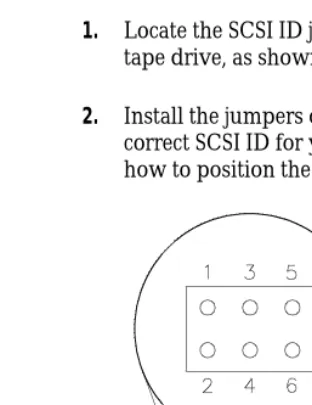
1. Locate the SCSI ID jumper block on the back of the tape drive, as shown in Figure 1.
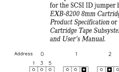
[image:11.612.223.379.339.541.2]2. Install the jumpers on the jumper block to obtain the correct SCSI ID for your configuration. Figure 2 shows how to position the jumpers for SCSI IDs 0 through 7.
Setting the SCSI ID with a Remote Switch
If you want to set the SCSI ID remotely, you can attach a remote switch assembly (not provided with the tape drive) to the tape drive’s SCSI ID jumper block. To set the SCSI ID with a remote switch, follow these steps:1. Locate the SCSI ID jumper block on the back of the tape drive, as shown in Figure 1.
2. If necessary, remove the jumpers from the pins.
3. Connect a remote switch to the jumper block. Ensure that the remote switch is no more than 30.5 cm (12 inches) from the jumper block. See Table 1 on page 9 for connector requirements.
4. Change the settings on the remote switch to the correct
[image:12.612.99.297.376.496.2]SCSI ID for your configuration. The switch settings should emulate the jumper positions shown in Figure 2.
Note: For specific information about pin assignments for the SCSI ID jumper block, refer to the EXB-8200 8mm Cartridge Tape Subsystem Product Specification or the EXB-8200SX 8mm Cartridge Tape Subsystem Product Specification and User’s Manual.
Preparing the Tape Drive for the SCSI Bus
The SCSI bus that you attach the tape drive to must be terminated correctly to ensure proper operation. The devices that are physically located at each end of the SCSI cable must have terminators installed. All other devices on the SCSI cable must not have terminators installed.
If the tape drive will be located at the end of the SCSI bus, you must terminate the tape drive. The procedure you use depends on whether the tape drive uses a single-ended or a differential SCSI configuration.
Terminating a Single-Ended Tape Drive
The single-ended tape drive includes three single in-line package resistor terminators (R-packs) that can be left in place if the tape drive terminates the SCSI bus.
CAUTION
The R-packs must be removed if the tape drive does not terminate the SCSI bus or if you plan to use an external SCSI bus termination.
Optional External Termination
If desired, you can terminate the single-ended tape drive externally by removing the R-packs from the back of the tape drive and installing an external terminator. Exabyte recommends a Methode Electronics, Inc. dataMate DM103-02-0 single-ended external terminator.
Removing the R-Packs
To remove the R-packs, follow these steps:
2. Using a pair of flat-nose wiring pliers, carefully grasp each R-pack at the center and pull it straight out. Be careful not to squeeze the pliers too tightly or you may break the R-pack.
Replacing the R-Packs
If you need to put the R-packs back in the tape drive, make sure that pin 1 of each R-pack is aligned with pin 1 of the socket and that no pins are bent. As shown in Figure 3, the writing on the R-pack should face upward. Pin 1 of the R-pack is marked with a colored line or dot and should line up with the right side of the socket.
CAUTION
[image:14.612.99.341.58.213.2]If you replace an R-pack, be sure to use the correct type to avoid damaging the tape drive. The tape drive uses three 8-pin, 7-resistor R-pack terminators, rated at 220/330 ohms. Replacement R-packs are available from Exabyte (part number 002196).
Terminating a Differential Tape Drive
The differential tape drive does not include internal terminators. If a differential tape drive terminates the SCSI bus, it must be terminated externally. See page 9 for information about the recommended terminator.
Connecting the SCSI Cable
The tape drive uses a standard 50-pin single-ended SCSI cable connector. Push the keyed connector on the SCSI cable on to the SCSI connector on the back of the tape drive. The connector is keyed so that it can be connected only one way.
Figure 4 shows the location of the SCSI connector.
[image:15.612.247.435.274.417.2]Note: The SCSI cable for connecting the tape drive to the host is not provided with the tape drive. Refer to page 36 for information about the requirements for the SCSI cable.
Installing the Tape Drive in a PC Drive Bay
If you are planning to mount the tape drive in a full-high PC drive bay, follow the guidelines in this section. Otherwise, refer to Appendix A for installation requirements, then resume reading on page 19, Performing the Initial Power On.”
Note: The steps for installing a drive in your computer may be different. Refer to your owner’s manual for specific instructions.
Before beginning, prepare your computer as follows:
1. Turn off the computer and attached devices.
2. Unplug the power cord.
3. Remove the computer’s cover as described in your computer owner’s manual.
4. Remove the cover plate(s) from the drive bay(s) you intend to use. Refer to your computer owner’s manual for instructions.
Note: For some computers you may need to use two half-high drive bays to accommodate the tape drive.
5. If necessary, remove one of the floppy disk drives to provide an empty full-high drive bay for the tape drive.
CAUTION
Mounting Procedure
Follow these steps to mount the tape drive:
1. Check for the presence of a load resistor in the computer. If it is present, disconnect the load resistor cable from the power supply. Refer to your computer owner’s manual for more information.
2. Use #6 × 32 screws to attach two slide rails to the sides of the tape drive (see Figure 5). The tapered end of each rail should point toward the rear of the tape drive.
3. From the front of the computer, thread the SCSI cable into the computer through the open bay. Slide the tape drive into the bay until the faceplate is flush with the front of the bay.
[image:17.612.216.456.198.356.2]4. Secure the tape drive to the drive bay as instructed in your computer owner’s manual.
5. Connect the SCSI cable to your SCSI adapter card (see Figure 6).
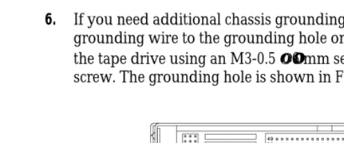
[image:18.612.100.346.83.281.2]6. If you need additional chassis grounding, connect a grounding wire to the grounding hole on the back of the tape drive using an M3-0.5 × 6 mm self-tapping screw. The grounding hole is shown in Figure 7. Figure 6 Inserting the drive into the drive bay and
[image:18.612.96.345.406.509.2]7. Connect power cable from the power supply to the 4-pin power connector on the back of the tape drive.
CAUTION
■ Make sure that the PC power is off before you
connect the cable.
■ Do not force the plug into the connector. The keyed
edges of the plug and the connector must match.
8. Replace the computer’s cover.
Performing the Initial Power On
The procedure you use to perform the initial power on depends on how long the tape drive has been stored. If you are not sure how long the tape drive has been stored, check the MLCH (machine level control history) label on the top of the tape drive to find out when the tape drive was
manufactured. Although the tape drive may have been operated since it was manufactured, for the purpose of the initial power on, assume that it has been stored throughout this period.
Tape Drive Stored for Less Than Six Months
If the tape drive has been stored for less than six months, the only step you need to perform for the initial power-on is to apply power to the tape drive.After POST completes, both the amber and green LEDs turn off , if there is no data cartridge loaded. If a data cartridge is loaded, the green LED remains on. The tape drive is ready for normal operation.
Important
If the amber LED does not go out after the power-on initialization and self-test are complete, an error has occurred. Contact your vendor.
Tape Drive Stored for Six Months or More
If the tape drive has been stored for six months or more, perform the following steps using your backup software to ensure that the tape drive’s internal lubrication is properly distributed:1. Apply power to the tape drive. The tape drive performs its POST as on page 19.
2. Locate a data cartridge that does not contain any valuable information. Set the write-protect switch to write enabled (see page 25).
3. Press the unload button on the front of the tape drive. Insert the data cartridge with the label side up and the write-protect switch facing you.
4. Push the door shut and wait while the tape drive loads the tape and positions it at LBOT. When the amber LED is off and the green LED is on, the tape is loaded and the tape drive is ready.
5. Write approximately 500 MBytes of data to the tape.
7. Repeat steps 5 and 6 at least two times or for two hours (whichever is greater).
Note: If errors occur, reset the tape drive and repeat steps 5 though 7 as appropriate. If the error recurs after the break-in period, contact your vendor.
2
Operating the Tape Drive
This section includes information about the following:
■ Reading the tape drive’s LEDs
[image:22.612.112.308.191.360.2]■ Setting the write-protect switch on the data cartridge ■ Loading and unloading a data cartridge
Figure 8 shows the controls and indicators on the front panel of the EXB-8200. (The front panel of the EXB-8200SX is identical.)
Reading the LEDs
The tape drive uses two LEDs to indicate its operating states. The LEDs indicate the following general conditions:
■ The green LED indicates that the tape drive can accept a tape access command.
■ The amber LED indicates SCSI bus activity and tape drive error conditions
Table 2 shows specific combinations of LEDs that may occur during tape drive operation. You may occasionally observe LED combinations and sequences not described in Table 2. These other combinations represent special or unusual conditions that are beyond the scope of this table.
Tape Drive State
LEDs (n = On o = Off
Amber LED Green LED
POSTa ■ ■
Power Up (with tape) o ■
Power Up (without tape)b o o
Servo errorc ■ o
Tape Inserted ( not loaded) o o
Tape Positioned at LBOT o ■
Unload o o
a The tape drive is performing power-on self-test diagnostics. This takes about 65 seconds.
b The green LED may go off before the amber LED if no tape is loaded. c Refer to page 26 for information about clearing servo errors.
Selecting Data Cartridges
[image:23.612.161.457.137.286.2]By selecting high-quality data cartridges and storing them properly, you can expect a long shelf-life and optimal data integrity from them. High quality tapes also help maintain tape drive reliability by minimizing wear on the recording heads.
Choosing High-Quality Data Cartridges
Available from Exabyte, EXATAPE 8mm Data Cartridges are formulated specifically for use in Exabyte products. EXATAPE data cartridges reduce head and tape path wear and have a shelf life exceeding 30 years when used according to recommendations. Available in three sizes (112m, 54m, and 15m), EXATAPE data cartridges are the only data cartridges recommended for use with all Exabyte products.
CAUTION
Exabyte strongly recommends that you use EXATAPE data-grade metal-particle media in the tape drive.
Never use video-grade tape for data storage.
Video-grade tape can be less accurate than data-grade tape when recording high-density data and more abrasive to tape drive recording heads. In particular, Exabyte strongly discourages use of the following types of video-grade tapes:
✗ Extended length” (such as 135-, 140-, and 150-minute tapes)
Setting the Write-Protect Switch
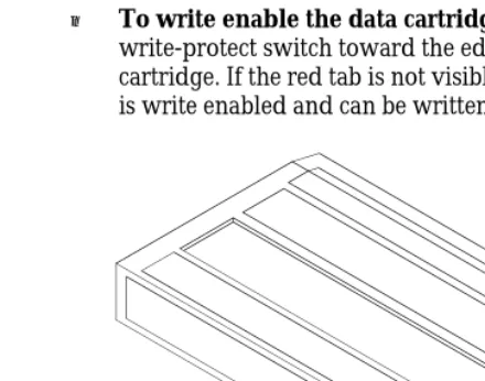
EXATAPE 8mm data cartridges are equipped with a write-protect switch, shown in Figure 9, to prevent data on the tape from being unintentionally overwritten.
Before loading a data cartridge in the tape drive, ensure that the write-protect switch is set correctly for the desired operation. You can use a ball-point pen or similar instrument to set the write-protect switch as follows:
■ To write protect the data cartridge, move the write-protect switch away from the edge of the data cartridge. If the red tab is visible, the cartridge is write protected and cannot be written to or erased.
[image:25.612.224.444.285.458.2]■ To write enable the data cartridge, move the write-protect switch toward the edge of the data cartridge. If the red tab is not visible, the data cartridge is write enabled and can be written to or erased.
Loading a Data Cartridge
To load a data cartridge into the tape drive, follow these steps:
1. Ensure that the write-protect switch is set correctly for the desired operation.
2. If you have just powered on the tape drive, be sure that the green LED is off, indicating that the tape drive has passed its power-on self-test and is ready to load the data cartridge.
3. If necessary, press the unload button to open the door on the tape drive.
4. Insert the data cartridge into the tape drive with the label side up and the write-protect switch facing you.
5. Gently close the door. The tape drive automatically loads the data cartridge and indicates ready status (green LED on).
Note: Most tape drives load the data cartridge
automatically. However, your application software may disable the autoload function. If the data cartridge does not go to the ready state after you close the door, consult your software documentation for information.
Unloading a Data Cartridge
Unload Button
The unload button is the only operator control on the tape drive. It is used to unload the tape from the tape drive.
To unload a data cartridge, press the unload button on the tape drive’s front panel. The tape drive completes the current operation, writes any buffered data to tape, rewinds the tape, unloads the tape from the tape path, and ejects the cartridge.
Error During Unload Procedure
If an error exists before or during the unload procedure, the unload sequence will be suspended and the amber LED will flash. To clear the error, press the unload button again. The unload sequence will be reattempted; however, unwritten data in the buffer will not be written to tape. The buffer and errors will be cleared.
CAUTION
3
Preventive Maintenance
The only routine maintenance required by the tape drive is regular cleaning of the tape drive heads and tape path. Use only an Exabyte or Exabyte-approved 8mm Cleaning Cartridge. Proper storage and maintenance of your data cartridges will maximize the shelf life of your tapes and assure data integrity.
Important
Using a cleaning method other than the Exabyte 8mm Cleaning Cartridge or an Exabyte-approved cleaning cartridge will void the warranty for the tape drive and can lead to premature head wear.
Determining When to Clean the Tape Drive
You should clean the tape drive’s heads and tape path either once a month or after every 30 tape motion hours,
whichever occurs first. However, if you are using the tape drive in a particularly dirty environment, or if you operate it infrequently, you may want to clean the tape drive more often than every 30 tape motion hours.
Using the 8mm Cleaning Cartridge
CAUTION
Do not rewind and re-use the cleaning cartridge. To prevent contamination of the tape drive and damage to the heads, do not use the cleaning cartridge for more than the number of cleaning cycles specified on the cartridge label. Reusing the material in the cleaning cartridge will redistribute contaminants previously removed from the tape path. Discard the cleaning cartridge after you have used it for the specified number of cleaning cycles.
To use the cleaning cartridge, follow these steps:
1. Apply power to the tape drive. When the power-on self-test is complete, press the unload button and remove any data cartridge from the tape drive.
[image:29.612.242.419.379.520.2]2. Check the usage record on the label of the cleaning cartridge to make sure that there is at least one cleaning cycle remaining (see Figure 10). If there are no cleaning cycles remaining, discard the cleaning cartridge and use a new one.
3. Insert the cleaning cartridge in the tape drive and close the door.
4. The cleaning cycle is performed automatically by the tape drive and takes approximately 15 seconds. When the cleaning cycle is complete, the cleaning cartridge is automatically unloaded and ejected from the tape drive.
Important
If there are no more cleaning cycles remaining for the cleaning cartridge, the tape drive ejects it without completing the cleaning cycle.
5. If the cleaning cycle was successful, record the date the cleaning was performed on the cleaning cartridge label. Store the cleaning cartridge for future use if it still has cycles remaining. Or, discard it if no more cleaning cycles remain.
Caring for Data Cartridges
To maximize the shelf life of your tapes and assure data integrity, follow these guidelines when storing data cartridges:
■ Place a label or other reference information on the cartridge adjacent to the write-protect switch.
■ Store cartridges in a cool, non-magnetic environment. Follow the cartridge manufacturer’s specifications for storage temperature and other environmental requirements. Do not allow the temperature and humidity in the storage environment to fluctuate.
■ Store data cartridges as soon as possible after you have written data to them. Immediate storage helps avoid many of the conditions that can damage tapes, such as temperature and humidity fluctuation, particulate contamination, and excessive handling.
■ Store data cartridges with the write-protect switch in the protected position. See page 25.
■ Store each cartridge on one of its long edges, not flat on its side (see Figure 11). When a data cartridge is stored on its side, the tape inside the cartridge is actually on its edge. In this position, stress is placed on the tape edges and can lead to tape damage. For the same reason, never stack cartridges on top of each other or lean them at an angle for extended periods of time.
Replacing Data Cartridges
[image:31.612.197.424.248.374.2]4
Packing the Tape Drive
You can ship the tape drive with either one drive per carton (single-pack) or with four drives per carton (four-pack). Figure 12 on page 33 shows the single-pack carton and packing materials.
CAUTION
■ To avoid damaging the tape drive and voiding your warranty, be sure to use the original shipping materials (or replacement materials obtained from Exabyte) when repacking and shipping the tape drive.
■ To ensure that the packaging meets the required specifications, do not modify the packaging in any way. The shipping carton and packing materials are not intended to be used for shipping items other than or in addition to a tape drive.
Table 3 shows the dimensions and weights of the single-pack and four-pack shipping cartons.
Size Dimensions Weight (with tape drive)
Single-pack
34.3 cm long × 27.3 cm wide × 22.2 cm high (13.5 × 10.75 ×
8.75 inches)
1 tape drive: 3.6 kg (8.0 lbs)
Four-pack
58.4 cm long × 34.9 cm wide × 29.8 cm high (23.0 × 13.75 ×
11.75 inches)
[image:32.612.49.345.371.508.2]Packing the Tape Drive for Shipment
To pack the tape drive for shipment, follow these steps:
1. Obtain the original shipping carton or contact your vendor to receive a new one.
2. Assemble the carton and tape it shut at the bottom with two-inch (51 mm) packing tape.
3. Place each tape drive in an antistatic bag. Tape the bag shut.
4. Place the bottom packing cushion in the carton, with the fitted area for the tape drive or tape drives facing up.
5. Single-pack shipping carton (Figure 12):
a. Place the tape drive into the fitted area in the packing cushion.
[image:33.612.245.423.331.543.2]b. Place the top packing cushion over the tape drive, with the cardboard side facing down.
6. Four-pack shipping carton:
CAUTION
Do not use the four-pack shipping carton for fewer than four tape drives. If you are shipping one, two, or three tape drives, use a single-pack carton for each tape drive.
a. Place four tape drives in the bottom packing cushion’s slots. You can place the tape drives in the packing cushion so that either the front or back panel faces up.
b. Place the top packing cushion over the tape drives.
7. Close the carton and tape the top seam so that the carton is completely closed.
Environmental Requirements for Shipment
When shipping a tape drive, be sure to comply with the environmental specifications shown in Table 4.
Temp. Range 40° C to +60° C (40° F to +140° F)
Temp. Variation
1° C per minute up to a maximum of 20° C per hour (2° F per minute up to a maximum of 36° F per hour)
Rel. Humidity 10% to 90% non-condensing
Wet Bulb 26° C max (79° F max)
[image:34.612.52.345.358.455.2]Appendix A Installation Requirements
This appendix provides specific installation requirements for the tape drive. It also provides guidelines for the following tasks:
■ Setting the SCSI ID with DIP switches
■ Selecting the correct SCSI cable and connector (pages 36 and 38)
■ Attaching the tape drive to a frame (page 38)
■ Providing chassis grounding (page 40)
■ Connecting the tape drive to the power supply (page 40)
If you have already installed the tape drive in a PC, you can skip this appendix.
Setting the SCSI ID with DIP Switches
In addition to the methods described on pages 11 and 12, some versions of the EXB-8200 and EXB-8200SX may use DIP switches for setting the SCSI ID. If your tape drive has DIP switches next to the SCSI ID jumper block, you can use these switches to set the ID.
Use the following steps if your tape drive can use DIP switches to set the SCSI ID.
1. Locate the SCSI ID DIP switches on the back of the tape drive.
2. Change the DIP switch settings to the correct SCSI ID for your configuration. Figure 13 shows the settings for SCSI IDs 0 through 7.
[image:35.612.211.404.436.535.2]On Off
3. Make sure that the remote switch or jumpers are set to SCSI ID 0.
Note: For specific information about the pin
assignments for the SCSI ID jumper block, refer to the EXB-8200 8mm Cartridge Tape Subsystem Product Specification and the EXB-8200SX 8mm Cartridge Tape Subsystem Product Specification and User’s Manual.
Important
If you are using a remote switch or jumpers to set the SCSI ID, make sure that the DIP switches are set to SCSI ID 0 (the default). Similarly, if you are using the DIP switches to set the SCSI ID, make sure that the remote switch or jumpers are set to SCSI ID 0.
If you set both the DIP switches and the remote switch to a particular SCSI ID, the actual SCSI ID will be the logical OR of the two settings. For example, if the remote switch is set for SCSI ID 1 and the DIP switches are set for SCSI ID 2, the actual SCSI ID will be 3.
Selecting a SCSI Cable
The SCSI cable for connecting the tape drive to the host is not provided with the tape drive. You must provide a cable that complies with the appropriate safety and regulatory agency requirements. To comply with FCC, Canadian DOC, and VDE limits, the tape drive requires shielded cables when the cables are external to the mounting enclosure.
General Requirements
Ideally, to match the cable terminators, the cable should have a characteristic impedance of 122 ohms (differential) or 132 ohms (single-ended). However, since cables with this high of a characteristic impedance are not generally available, somewhat lower impedances are acceptable. A characteristic impedance of 100 ohms ± 10% is
recommended for unshielded flat or twisted-pair ribbon cable. A characteristic impedance greater than 90 ohms is recommended for shielded cables.
Note: To minimize discontinuities and signal reflections, ensure that cables used on the same bus have the same impedances.
Cable Length Requirements for Differential
Configurations
For differential SCSI configurations, ensure that the sum of all the SCSI cable lengths does not exceed 25.0 meters (82.02 feet). A stub length of no more than 0.2 meters (8 inches) is allowed off the mainline interconnection within any connected equipment. The stub length within the tape drive is less than 50 mm (1.97 inches).
Cable Length Requirements for Single-Ended
Configurations
SCSI Cable Connector
To connect the tape drive to the SCSI bus, use a 50-pin female ribbon cable connector (AMP No. 1-746285-0 or equivalent). The SCSI connector is located on the back of the tape drive. The connector is a 50-pin male ribbon cable connector, consisting of two rows of 25 pins with adjacent pins 2.54 mm (0.1 inch) apart. For information about the specific SCSI connector pin assignments for differential and single-ended tape drives, refer to the EXB-8200 8mm Cartridge Tape Subsystem Product Specification and the EXB-8200SX 8mm Cartridge Tape Subsystem Product Specification and User’s Manual.
Attaching the Tape Drive to a Frame
The main housing of the tape drive includes two sets of mounting holes (one set on the sides and one set on the bottom, as shown in Figures 14 and 15) to allow for a number of mounting positions. These mounting holes accommodate #6-32 screws. Refer to the EXB-8200 8mm Cartridge Tape Subsystem Product Specification and the EXB-8200SX 8mm Cartridge Tape Subsystem Product Specification and User’s Manual for detailed information about the spacing of these mounting holes.
When mounting the tape drive, follow these guidelines:
■ The mounting location must meet the environmental requirements discussed in the EXB-8200 8mm Cartridge Tape Subsystem Product Specification and the
EXB-8200SX 8mm Cartridge Tape Subsystem Product Specification and User’s Manual. These requirements specify limits for operating temperature, humidity, airflow, particulate contamination, shock, and vibration.
■ Use either the four mounting holes on the sides or the four mounting holes on the bottom (A” or B,” as shown in Figures 14 and 15). Using combinations of mounting holes from different sets may distort the frame.
■ Objects such as screw heads, cables, or adjacent devices must not press against the frame of the tape drive.
■ The ventilation slots at the sides and top of the tape drive must be free of obstruction so that adequate airflow is provided.
[image:39.612.208.409.228.375.2]■ There must be sufficient space to access and operate the front panel controls.
Chassis Grounding (optional)
If additional chassis grounding is desired, connect an M3-0.5 × 6 mm self-tapping screw to the grounding hole. The grounding hole is shown in Figure 7 on page 18.
Note: The power supply returns are connected to the chassis, so you cannot isolate logic common ground from chassis ground.
Power Cable Connector
The tape drive operates from standard +5 VDC and +12 VDC supply voltages; it cannot use external AC power. Safety agency certification requires that the supplied voltage be from a Safety Extra-Low Voltage source (per IEC 950). Refer to Appendix B for tape drive power specifications.
CAUTION
[image:40.612.99.305.52.216.2]The power connector used in the tape drive is compatible with power connectors used for standard 5.25-inch devices. To connect the tape drive to a power cable, use an
Appendix B Tape Drive Specifications
GeneralFront panel Unload button, LED indicators for
SCSI activity, tape motion,and errors
Back panel SCSI cable connector, power
connector, jumper block and DIP switch for SCSI ID, SCSI terminator R-packs (single-ended configuration)
Interface SCSI-1, single-ended or differential
Physical Characteristics
Form factor 5.25-inch full-high
Size 82.5 mm (3.25 inches) high×
146.0 mm (5.75 inches) wide× 203.2 mm (8.00 inches) deep
Weight 2.045 kilograms (4.5 pounds)
Environmental
Operating temperature +5°C to +40°C (+41°F to +104°F)
Non-operating temperature –40°C to +60°C (–40°F to +140°F)
Operating rel. humidity 20% to 80% Non-operating rel. humidity 10% to 90%
Data Handing
Maximum burst, asynchronous
1.5 MBytes/sec.
Typical burst 1.2 MBytes/sec. Sustained 246 KBytes/sec
Capacity 2.5 GBytesa
^
Power and Reliability
^ Supply voltages Standard +5 VDC and +12 VDC±5% ^
^
Tolerance 125 mVpp max.b Maximum current 2.8 Amps at +5 VDC;
0.40 Amps at +12 VDC
Average power consumption
10.41 watts at +5 VDC; 4.48 watts at +12 VDC
Mean time between failure 40,000 hours @ 10% duty cycle
a
EXATAPE 112m Data Cartridge (8200 format). b
Index
C
cable requirements power cable 40 SCSI cable 36 – 37 cartridges
See data cartridges
chassis grounding 18, 40 cleaning the tape drive
frequency 28 instructions 29 condensation 10 D
data cartridges care of 30 – 31 loading 26 replacing 31 storing 30 – 31 unloading 26 – 27 write-protect switch 25 differential SCSI
cable requirements 37 termination 9, 15
DIP switches for setting SCSI ID 35 E
electrostatic discharge 10
EXATAPE 8mm Data Cartridge 24 G
grounding, chassis 18, 40 H
handling the tape drive 10 I
installation
attaching tape drive to a frame 39 attaching to a frame 38 – 39 cable requirements 36, 38 connecting the power supply 19 connecting to the SCSI bus 13, 15 grounding 18, 40
power cable requirements 40 setting the SCSI ID 11, 35 J
jumpers for setting SCSI ID 11 L
LEDs location 22
states indicated by 22 – 23 load procedure 26
M
maintenance
See preventative maintenance
mounting requirements 38 – 39 O
operating the tape drive 22 – 23, 26 – 27 P
packing the tape drive 32 – 34 power cable requirements 40 power supply
connecting tape drive to 19, 40 preventive maintenance 28 – 29 R
R-packs 13 – 14
remote switch for setting SCSI ID 12 resistor terminators 13 – 14 S
safety standards 3 SCSI bus
cable requirements 36, 38
connecting the tape drive to 13 – 15 differential SCSI 37
single-ended SCSI 37 stub length 37 termination 9, 13 – 14 SCSI ID
requirements for setting 11 setting with DIP switches 35 setting with jumpers 11 setting with remote switch 12 shipping the tape drive 32 – 34 single-ended SCSI
cable requirements 37 termination 13 – 14 T
tape drive
cleaning 28 – 30
controls and indicators 22 – 23 installation 9 – 14, 19 – 20, 38 – 40 loading a data cartridge 26 packing and shipping 32 – 34 providing chassis grounding 18 unloading a data cartridge 26 – 27 unpacking 10
terminators for SCSI bus 9, 13 – 15 U
Exabyte Corporation 1685 38th Street Boulder, Colorado USA 80301