0
BSc Thesis
GUIDELINES
STRUCTURAL
ANALYSIS IN BIM
Author:
R. Kemerink
Mail:
[email protected]
Company:
Schreuders Bouwtechniek
1
PREFACE
This basis for the research originates from my interest in the development of BIM, accompanied by my passion for architecture and structural engineering. As BIM is developing on different areas, the integration of all disciplines into one model is not there yet. How can we move forward to a more integrated BIM approach? It is my passion to find out and develop new possibilities and to improve the current situation in the building industry.
2
TABLE OF CONTENTS
Summary... 3
1. Introduction ... 4
1.1. Background ... 4
1.2. Problem Statement ... 5
1.3. Objectives and Research Questions ... 6
1.4. Contribution and Relevance ... 6
1.5. Terminology, Limits and Boundaries ... 7
2. Methodology ... 8
2.1. Research Phasing ... 8
2.2. Research Design ... 8
2.3. Verification & Validation ... 10
2.4. Research Design – Finalizing ... 10
3. Literature Review ... 11
3.1. Design Process ... 11
3.2. Application of BIM ... 11
3.3. Interoperability ... 12
3.4. IFC ... 13
3.5. Robot ... 14
3.6. Comparison IFC and Robot ... 14
4. Analysis of Current Workflow ... 15
4.1. Interviews ... 15
4.2. System Requirements ... 19
5. Concept Structural Analysis... 20
5.1. Proposed Method... 20
5.2. Interoperability with Structural Analysis Software ... 22
5.3. Modification in Spreadsheet ... 23
6. Verification & Validation ... 25
6.1. Verification Concept ... 25
6.2. Validation Concept ... 26
7. Discussion ... 28
8. Conclusion & Recommendations ... 29
References ... 31
3
SUMMARY
This document contains the research for the BSc Thesis that focusses on one of the features of Building Information Modelling (BIM), structural analysis, which is the determination of the effects of loads on physical structures and their components. The purpose of this research is to identify possible trajectories for the incorporation of the structural analysis in the BIM process, to develop a middleware that interacts between the architectural and structural design disciplines, and to recommend a practical solution for the client to adapt their workflow towards a more integrative structural design that can ensure improvements in efficiency of the design. The main questions of this research are; which technique can be adopted by the client for the better integration of structural analysis in their BIM process and workflow and how can this be integrated.
The research consists of two phases. The first phase is the preparation phase which is intended to gather background information about the subject. Therefore, a literature review containing state-of-the-art knowledge about this subject is presented, where the possibilities and difficulties that are present concerning structural analysis in BIM are investigated. Furthermore, this research contains interviews with employees at the company to investigate the current situation of the BIM workflow and to discuss this. The aim of this is to develop sufficient background knowledge for developing a strong argumentation to support the recommendations. Based on literature and interviews, a few trajectories for the integration of structural analysis are introduced, along with a new concept that entails an improvement on the information exchange between the different disciplines during a building project. The second phase is the production phase in which new knowledge is generated. New tools are developed to support the new concept. These tools have been verified by testing it on different projects and validated by giving a workshop to the employees and starting a conversation about the tools.
4
1.
INTRODUCTION
1.1. Background
In the past few years, the use of Building Information Modelling (BIM) has become conventional in the Architecture, Engineering and Construction (AEC) industry. BIM is a 3D model-based process that gives AEC professionals the insight and tools to integrate design and planning, so the industry is able to more efficiently plan, design, construct, and manage buildings and infrastructure [1]. The use of BIM in the AEC industry has established results like cost and time reduction, communication, coordination, and quality improvements [2]. Adapting the BIM method will help companies in the AEC industry to work more time and cost efficiently.
Building on Object-Oriented (OO) paradigm, BIM allows to integrate various types of project-related data (e.g., planning, material characteristics and quantities) in a single (or federated) model in a systematic way. Object-Oriented Programming (OOP) is based on objects. An object can be a variable, a data structure, a function or a method. Objects in BIM can contain non-geometrical information (e.g. material characteristics and costs). These objects can be organized into classes, so they can be gathered together. The objects can interact with each other and developers can add attributes and behaviour to them and focus on programming how objects are related and interacting with each other [3].
The purposes of using BIM lays with several aspects. The most obvious aspect is the visualisation that has been provided by the 3D model. A visualisation of the project results in a better customer services because proposals can be better understood. Also, the objects inside the model can easily be converted to a shop drawing, which is a detailed construction and fabrication drawing. Furthermore, BIM models can be used for: code reviewing, e.g. the fire department; by adding value to materials used in the model a BIM model can provide a cost estimate; construction sequencing which provides a better overview of the fabrication process and the building components on site or their delivery status; clash detection, e.g. interference of the window placements with the electricity cables; forensic analysis like an evacuation plan; and facility management [4].
5 1.2. Problem Statement
BIM is becoming the midpoint of information for stakeholders to elaborate on building projects. The more information is present in a structured way, the easier it will be to share information with other stakeholders involved in the project. A prevalent trend in the workflow of many companies in the AEC industry, is that structural analysis is not integrated within BIM. The issue present is that the architect and the engineer are both working on the same project but on different dimensions (i.e., one focuses on functionality/aesthetic and the other one on structural soundness/engineering). In case of the client, the architect is making the architectural design with the use of CAD and the engineer is analysing the structural design with the use of calculations in spreadsheets and other calculation software. Companies are not taking the full advantage of the communication and translation possibilities (i.e., the conversion of the architectural model into the structural model) that are possible in BIM. The issue described is called the lack of interoperability. For the structural aspect of the design, the architectural models are reduced and translated to only contain the mechanical sense of the model, e.g. the beam-truss structure. Then, a structural analysis will be carried out to analyse the stability of the structure. The structure needs to be optimized, which means adjustments to the structure will be done and the structural analysis has to be carried out again. This is an iterative process and will go on until design objectives are met. After optimizing the structure, it can be proposed for purchasing and fabrication steps. Even after this step changes are possible due to manufactory, and material arrangement issues. Requests to redesign can be raised both for architectural and structural concerns, which means that the information flow between the different stakeholders is very important. Changes in the architectural perspective might require a new structural model. This orthodox structural design approach lacks the ability to easily adopt to redesign requests and handling interactive and cooperative abilities at early conceptual design stages.
6 1.3. Objectives and Research Questions
The purpose of this research is to (1) identify possible trajectories for the incorporation of the structural analysis in the BIM process, to (2) develop a middleware that interacts between the architectural and structural design disciplines, and (3) to recommend a practical solution for the client to adapt their workflow towards a more integrative structural design that can ensure improvements in efficiency of the design. The meaning of ‘efficiency’ in this research is reducing time and costs, and improving communication, coordination and quality. This will be done by developing a guideline for integrating the structural analysis within BIM for the client.
The main question of this research is: “Which technique can be adopted by the client for the
better integration of structural analysis in their BIM process and workflow and how can this
be integrated?”. The main question is supported by the following research questions: Q1. Which BIM-compatible and BIM-supporting approaches/tools are available for
structural analysis?
Q2. What is the current scope of BIM application at the company?
Q3. Which method is the client currently using for the structural analysis? Q4. Which approach/tool better fits the BIM workflow of the company? Q5. How can the company best adopt the identified approach/tool?
1.4. Contribution and Relevance
Considering the client, the immediate contribution is an advice that fits the client’s workflow,
so it can adopt to a more integrated structural analysis and achieve a higher efficiency in their structural design process. Additionally, the findings of this study will contribute to improvements in the AEC2 industry, especially in the field of engineering. Engineering is of
great importance for guaranteeing safety during the construction and the use phase of a building. An integrated structural design would help the AEC industry with optimizing their structural design. An optimized design could result in improvements on cost efficiency and sustainability. This study will give the AEC industry guidance in the adoption of an integrated structural design by investigating and reviewing several possible trajectories.
7 1.5. Terminology, Limits and Boundaries
Terminology
AEC Architecture, Engineering and Construction
Autodesk Revit (Revit) BIM-software that includes features for architectural design, MEP (mechanical, electrical, and plumbing) and structural engineering, and construction
BIM Building Information Modelling
BIM model A digital model of an existing and/or planned building that consists of objects which contains information
CAD Computer Aided Design
Dynamo Visual programming environment that works with Revit and other software
FEM Finite Element Method
IFC Industry Foundation Class
Interoperability The ability to exchange data between applications to facilitate automation and avoidance of data re-entry
MVD Model View Definition
Robot Structural Analysis
Professional (Robot) BIM-software that is able to test the effects of structural loads and verify code compliance Structural analysis The determination of the effects of loads on physical
structures and their components
Limits and Boundaries
The limited timespan of this research makes it more difficult to validate all the possible trajectories for the incorporation of the structural analysis in the BIM process. Therefore, the research will verify and validate the method that is most suitable for the client.
8
2.
METHODOLOGY
This chapter explains the process of this research. In section 2.1 the processes will be grouped into 2 main phases and 7 sub-phases. In the following sections the process steps are presented, and it will be made clear how data for this research is collected, which research techniques are used and how information is analysed.
2.1. Research Phasing
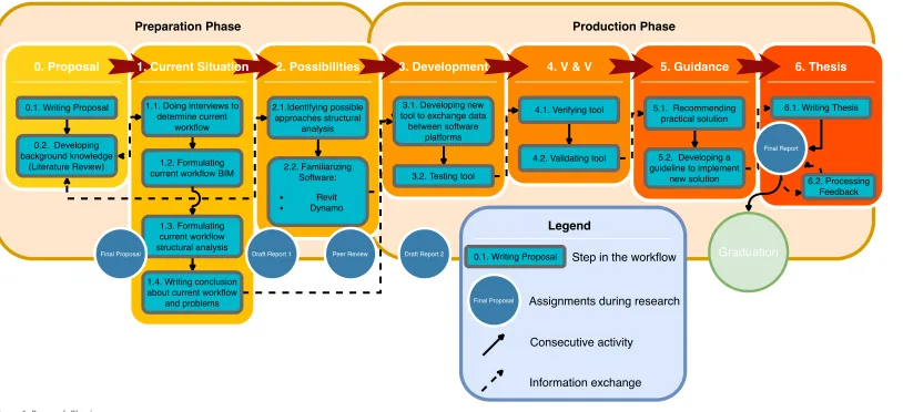
A global phasing of the project is presented in Figure 1. The whole research is categorized into two main phases; the preparation phase and the production phase. The preparation phase is intended to gather background information about the subject. The production phase is intended to develop the integration method. Every task has been given a number based on the phase and order. The process steps will be discussed in the upcoming sections.
2.2. Research Design
The beginning of this research is focussed on the first research question (Q1) “Which BIM-compatible and BIM-supporting approaches/tools are available for structural analysis?”. Several articles have been read to find out what has been done on this topic. An overview of the information about this topic is presented in a literature review (0.2) in section 3. This information is useful for the research because it provides insight into the possibilities and potential trajectories. The literature review will focus on (1) the existing solutions for the integration of structural analysis in the BIM process, and (2) how these new solutions affect the workflow of the stakeholders involved in a project. The findings of the literature review will be integrated with the answers to Q2 and Q3, to identify a potential solution that fits the
workflow of the client’s company.
Thereafter, the research questions (Q2) “What is the current scope of BIM application at the company?” and (Q3) “Which method is the client currently using for the structural analysis?”
will be answered. Both questions will help defining the source of the problem and will help identifying what possibilities for the integration of structural analysis in BIM fit the workflow of the client. To get answers to these questions, interviews (1.1) are held with employees working with BIM and structural engineering. The interviews are presented in section 4.1. The client is mainly working with Autodesk Revit which is BIM-supporting software that includes features for architectural design, MEP3, structural engineering and construction. It is
crucial to develop some basic understanding of the features and possibilities of Revit before next step of the research can be taken. Therefore, I must become familiar with Revit (2.2). Working with online tutorials will help attain knowledge and skills of Revit. Another software program I must become familiar with is Dynamo [7]. Dynamo is a visual programming environment that works with Revit. It can be used for manipulating data, generating geometry, automating processes, and connecting applications. Dynamo could be the tool that can be used to create a new medium where the information flow between the architect and the engineer can be improved by programming. In this research, Dynamo can be used to transfer data between different applications like Revit and Excel.
9
10 After finishing the preparation phase, with all background information and skills prepared, the research will continue with the production phase. Based on the findings of the literature review and the interviews, a method for integrating the structural analysis in BIM (3.1) will be designed. The design needs to fit the workflow of the client and help solving the missing integration of structural analysis in BIM.
2.3. Verification & Validation
When succeeded with phase 3, the method has to be verified and validated (4.1 – 4.2). The tool will be reviewed and verified based on the proper functioning of the system. The system is working properly if the tool is exchanging the data between the different software programs correctly. This will be verified by checking if the data that has been transferred corresponds to the data that would normally be present in the old workflow.
The validation will be based on the ability of the tool to meet its core objectives. A few criteria the tool will be evaluated on:
- Transferability: the tool should be able to transfer data from one software program to another without any errors or data loss. Without this criterion the tool would be useless to adopt to because it does not function properly.
- Usability: the tool should be easy to use. If there are many actions required from the user, or the tool is too difficult to understand and will be prone to errors made by the user.
- Time efficiency: the tool should not be slower compared to the old process. If the tool takes a lot of time, the whole project process will be slowed down.
- Applicability: it is preferred to use the tool in any case possible. If the tool can be used in complex projects, it will score high on this criterion.
2.4. Research Design – Finalizing
Depending on the review of the newly designed tool, a recommendation (5.1) will be provided for a practical solution for the client to adapt their workflow towards a more integrative structural design that can ensure improvements in efficiency of the design.
11
3.
LITERATURE REVIEW
This chapter contains a literature review of articles relevant to the subject of this thesis. There are a few topics that need to be investigated to provide background knowledge on the subject. The first topic is the current situation of the processes involved in a building project. This information serves as background information for the interviews in section 4. The following topic is BIM. What are the advantages and are there disadvantages or issues? What are the latest developments in BIM and how will BIM develop in the future? The other topic is structural analysis. To what extend is it used in BIM? What are the bottlenecks when applying structural analysis? And (Q1) which BIM-compatible and BIM-supporting approaches/tools are available for structural analysis?
3.1. Design Process
Because both processes are part of the whole design process of a building project, it is important to know the phases of a design process. The initial phase of a building project is the (1) sketch design which contains the wishes of the client, a program of requirements, the environmental situation, and the opportunities and limitations. Next the (2) preliminary design is elaborated. This is the first spatial and aesthetic design of a project to be represented to the client. Using 3D visualisations, the design can be clarified to the client who can give feedback or make additional wishes. In this phase there is still opportunity to make changes. After this opportunity the next phase is the (3) final design. In this phase the spatial relations, the appearance, the main dimensions and the materials are established. This design is technically elaborated in the (4) technical design phase. This phase contains the elaboration of material connections, the foundation, and a beam plan. Furthermore, the principle details are drawn. A principle drawing describes the way something (i.e. roof and frame connections) works or is put together (e.g., detailed drawing). The final phase is the (5) working drawings (e.g., fabrication/shop drawings) which contains the final dimensions and the structural information. This phase is followed by the execution. [8]
3.2. Application of BIM
Predominantly architects are using BIM, which can also be confirmed by the fact that one of the major application areas of BIM is the conceptual design support, which has been concluded out of a survey [9]. The same survey also showed that BIM users believed that BIM had a positive impact on the productivity of the company and improved the project outcomes, for example the reduction of requests for information (RFIs). Because RFIs are time consuming, the fewer RFIs the better the performance of a company will be. A few years ago, Azhar [4] stated that BIM had a lot of potential to develop in different fields.
12 3.3. Interoperability
Besides these advantages of BIM, there are still some issues present. Among others, interoperability is one of the greatest risks involved in the application of BIM. Because most structural analysis software based on FEM already existed before BIM, there are no proper standards for sharing information between these programs [11]. Interoperability is highly important for the performance of BIM. Therefore, the lack of interoperability is causing problems for companies which are working with different tools and programmes. The integration via open standards is critical in providing the information exchange throughout the project lifecycle [12]. Currently, two formats are being used for the integration of BIM models: Industry Foundation Classes (IFC) and green building Extensible Markup Language (gbXML). IFC describes geometry information, material properties and the relationships in a BIM model [13]. The gbXML schema facilitates the exchange of data between BIM models and Building Performance Simulations (BPS) tools [14]. Although, both formats are widely accepted by the AEC industry, its adoption does not ensure a data exchange without problems. The IFC schema does not capture the ways information is created and shared by practitioners [15]. And, gbXML is limited to simple design solutions because it lacks the ability to read complex geometries [16]. The client is working with the IFC scheme and is likely to have the same problems described. In the research the lack of interoperability between programmes and tools that the client is using will be tried to solve with the use of Dynamo. Usually, current issues on the development of structural design involve (1) the lack of flexibility, (2) dull or time-consuming labour works, and (3) communication gaps with different design aspects. (4) The space for discovering new and improved design solutions at early stage has been limited. Also, (5) the lack of unified data sources within the architectural and structural models are making it hard to covert data between the two models. The last issue
can be described by the terms ‘Lack of Interoperability’ [17].
BIM-enabled structural analysis is solving the lack of interoperability that is present between architectural and structural concerns. By its nature, most structural design elements are already present in a BIM model [17]. Which means they might only need minor adjustments to make BIM-enabled structural analysis possible. For example, the architect (and/or BIM modeller) could consider more factors other than geometrical properties during the architectural modelling process.
Implementing structural analysis in BIM has several advantages, such as not only considering the structural criteria, but becoming more conscious about the usability (e.g., safety, functionality) of the building as well. Another advantage is that higher level of communication between the stakeholders can result in better and more complex design solutions. Besides, with structural analysis in BIM it is possible to adjust throughout the design process and visualise the effects of different design options through analysis. On the other hand, there are a few issues that come along with BIM. An important issue is the loss of information during data exchange processes. In the future, BIM-enabled structural analysis will become more popular and the advantages are expected to become even bigger, which will result in more functional, sustainable and safer buildings. [17]
13 3.4. IFC
[image:14.595.76.520.167.253.2]An approach that is more collaborating with BIM is extracting and translating (Figure 2) information from the BIM model with the use of IFC. The structural information present in the BIM model can be stored in an IFC file, which can be imported by different structural analysis software programs. However, IFC comes with several difficulties. Three main difficulties of IFC will be discussed.
[image:14.595.181.405.230.416.2]Figure 2. Conversion of BIM model [18]
Figure 3. Wrong alignment [19]
(1) When designing the 3D model in Revit, the BIM modeller is not connecting the structural columns and beams properly. This results in a structural model where nodes are not connected the way they should be to carry out a proper structural analysis (Figure 3). This issue is also noticed in the article of Zotkin et al. [11], where they describe it as the inconsistencies in the vertices of elements. The coordinates of the nodes need to be aligned manually in the right node that bears the load. This is additional work that should be avoided. The paper of Ramaji et al. [19] discusses the development of a mechanism for the transformation of IFC building information models in the Coordination View to their equivalent structural models in IFC Structural Analysis View4 (SAV). The model automates the
transformation, modification, and additional operations that are necessary during the exchange of information between the different software programs. The paper describes how the nodes that are not aligned properly are merged to one point.
(2) Another difficulty of exchanging data with IFC is the fact that software programs implement the information in the IFC file in different ways which leads to inaccuracy. A tool has been designed to solve this issue [18]. It uses algorithms that overcome the differences in the representation syntax and grammar of different structural analysis software. MVDs defined by BuildingSMART are good solutions for the exchange of information. However, the IFC SAV has not been updated since 2007. Instead, they have developed IFC4 Design Transfer
14 View (DTV) which has been released in 2015. IFC4 DTV basically covers the IFC SAV. However, IFC4 DTV has one disadvantage.
(3) The receiver of the IFC file is able to suggest/demand changes, and changes may be made to the model directly. But, bidirectional exchange of information (i.e. making changes and send the full model back to continue) is out of reach. This is fine for data exchange processes that are linear. When one process is over, the other one can start. However, the data exchange between the architect, BIM modeller and the engineer involves a iterative process where readjustments are being made during the design process. Therefore, having to make suggestions/demands to make changes takes more time compared to having a bidirectional exchange of information. BuildingSMART suggests using their Open BIM Collaboration Format (BCF) to support solving this issue [20]. BCF gives structure to the way suggestions or demands are being written down. The format offers the possibility to add remarks, screenshots etc., on top of the IFC model layer. It separates the communication from the model which improves the coordination between parties [21]. It is a format that allows the addition of textual comments, screenshots and more on top of the IFC model layer for an improved communication Despite the development of IFC and the number of tools that provide IFC import and export, IFC is still used to a limited extend in the construction industry due to the various challenges which the industry faces. [22]
3.5. Robot
Besides working with different software programs, it is also possible to integrate the structural analysis within Revit with the use of the Structural Analysis Toolkit. The toolkit supports the BIM process and allows structural engineers to analyse and check the structure within the Revit environment. The analytical model created in Revit can be extended to Autodesk®
Robot™ Structural Analysis Professional (Robot). The tool has a bidirectional link between Revit and Robot and is able to; transfer a structural model from Revit to Robot and vice versa, update a structural model in one program after making readjustments in the other program, and transfer results of a static analysis and required reinforcement calculated in Robot to the Revit model [23]. This approach holds the same difficulty as IFC, namely the wrong alignment of structural elements (difficulty 1). To use the integration with Robot, this issue needs to be solved.
3.6. Comparison IFC and Robot
15
4.
ANALYSIS OF CURRENT WORKFLOW
In this chapter the interview questions and its results will be presented. Along with the literature review, the interviews frame the prior knowledge of this subject. Based on the interviews, the current workflow is elucidated and visualised with the use of a diagram. Besides, the interview can be seen as an introduction of my research to the employees that are involved and to make sure that they are aware of what my research entails. Therefore, the employees are able to help me with follow-up questions during my time at the company.
4.1. Interviews
[image:16.595.67.527.463.755.2]To answer the second and third research question, (Q2) “What is the current scope of BIM application at the company?” and (Q3) “Which method is the client currently using for the structural analysis?”, a BIM modeller and a structural engineer working at the company have been interviewed. The BIM modeller is responsible for creating and maintaining the BIM model. I have asked the BIM modeller a set of questions that can be found in Table 1. The questions are related to the process of his work and the purpose is to find out if he is noticing any difficulties in their work and establish the communication issues that arise with the structural engineering part of BIM. The structural engineer is carrying out the structural analysis of building projects. The questions for the structural engineer can be found in Table 2. The main purpose of the interview is the same as the interview with the BIM modeller and is focussed on discovering the current challenges that are present. Another purpose of the interviews is to start a conversation amongst the employees and to discuss future possibilities. During the interviews, I took notes to document the interview. In the next section, the results of the interview with the BIM modeller will be presented in the next subsection followed by the structural engineer in the subsequent subsection.
Table 1. Interview format BIM modeller
Question Relevance of question
What is your profession? And how would you describe it?
Before going in depth, it should be clear what the employees’
contribution to the company is. What is the input, the process and
the output?
Sketching a clear information flow of all the information that is input and the information that is produced along with the conversion of this information. (Q3)
How goes the communication between you and the structural engineer/BIM modeller?
To find out whether internal communication could be an issue.
With which other stakeholders do
you have contact, and how? To find out whether external communication could be an issue. Where are the difficulties? What
is error-prone? What issues do occur?
Trying to find out if the employee is aware of difficulties mentioned in literature or if the employee has other difficulties that are not mentioned yet.
What information is present in the
BIM models you are creating? Finding out what the scope of BIM is. (Q2) In what Level of Detail are you
working?
16
Table 2. Interview format Engineer
Question Relevance of question
What is your profession? And how
would you describe it? Before going in depth, it should be clear what the employees’ contribution to the company is.
What is the input, the process and
the output? Sketching a clear information flow of all the information that is input and the information that is produced along with the conversion of this information. (Q3)
How goes the communication between you and the structural engineer/BIM modeller?
To find out whether internal communication could be an issue.
With which other stakeholders do you have contact, and how?
To find out whether external communication could be an issue.
Where are the difficulties? What is
error-prone? What issues do occur? Trying to find out if the employee is aware of difficulties mentioned in literature or if the employee has other difficulties that are not mentioned yet.
To what extend are you involved in
BIM? Finding out if he is working with BIM, how much knowledge he has of BIM.
Results Interview BIM modeller
The process of the BIM modeller starts with the receipt of a grid plan derived from an architect. Additionally, he receives the principle details from an architectural office. Initially, the BIM modeller designs a model based on a ‘closed box’ concept. This concept contains the
spatial objects in terms of spaces or volumes (i.e., there are just walls and no cut-outs). The contractor is appointed to design the shell of the building, which holds the location of the windows and doors. Afterwards, the BIM modeller will receive back the model with the additions of the contractor. The additions need to be checked on feasibility by the BIM modeller. After the technical design, the installer has some MEP additions to the project as well. Frequently, these adoptions are too late, which means that readjustments need to be done. Readjustments might also influence the structural analysis which might require recalculation. This will result in a lower operational efficiency. After the readjustments, the BIM modeller will design the working drawing. To find out to what extent the client is working in BIM, I have asked the BIM modeller in what Level of Detail (LOD) he is working in BIM. The LOD describes a state of development or detail the BIM model is in. LOD is used in agreements between different project stakeholders to determine the accuracy of the model in a certain time frame. The BIM modeller at the company is working between LOD 300 and LOD 400, which means that the objects are materialized and exact in terms of dimensions, shape, location, orientation and quantities. Besides, the objects contain additional information concerning the detailing, the manufacturing of components in factories, and the assembly of components on site [25].
17 project are not passed on properly. The BIM modeller emphasises the lack of proper communication and deliberation that comes along with it.
Results Interview Engineer
As an engineer he is calculating, and designing steel, concrete, or wood constructions for projects, varying from bigger projects like the construction of the city hall of Hengelo, to projects like the installation of a dormer. The engineer is especially involved in a lot of smaller projects. This makes him less involved in the BIM workflow, because BIM is mainly used in bigger projects. The use of BIM in smaller projects does not really show improvements on efficiency which makes using BIM redundant. Just like the BIM modeller, the first information the engineer receives, originates from the architect of the project. From these sketches he makes the first calculations for the construction. For this he uses several tools depending on what to be calculated. Excel is used for quick calculations, Technosoft’s calculation software
is used to calculate 2D structures (portals and trusses), and for 3D structures he uses AxisVM. AxisVM is a calculation tool based on the Finite Element Method (FEM). For example, AxisVM can provide a floor plan containing an approximation of the deflection of the floor using a heat map. AxisVM and Technosoft are both BIM compatible, which means that information between these programs can be imported and exported to BIM models with the use of IFC. In this phase, the reinforcement is not included yet. The output of the engineer consists of an advice to the client of the project. The advice contains the dimensioning of the construction. This information will be returned to the architect or the contractor for further adjustments. The process of the structural analysis is an iterative process depending on the phase of the design process. Every phase, the dimensioning of the structure will become more detailed. The final detail to be included is the reinforcement.
18
Conclusion Interviews
Concluding from both interviews, communication is very important. There is a lot of information going back and forth between stakeholders. It is especially difficult to work with stakeholders outside the company. Inside the company there is the lack of smooth interoperability between the different methods of the BIM modeller and the structural engineer. Considering the research questions (Q2) “What is the current scope of BIM application at the company?”, the client is already working on a detailed level in BIM (LOD300+), although the current situation does not involve any sort of structural information in BIM except for material characteristics and the analytical lines (Figure 2, p. 13, Structural Model). For example, how beams are connected to each other (e.g., clamping, hinge) is not included in the model, as well as forces that occur on the building. This information which is necessary for the structural analysis is generated in different software programs. This brings us to the third research question (Q3) “Which method is the client currently using for the structural analysis?”. Currently, the client is using mainly calculation software from Technosoft. The software requires a manual drawing/input of the structural model which is a time-consuming process.
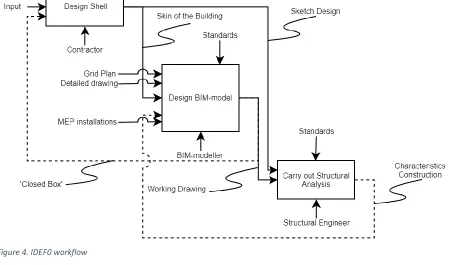
With the aid the background knowledge about the design process described in the literature review, and the results from the interviews, the workflow is visualised with the use of an IDEF05 box diagram (Figure 4). In this workflow there are several flows (dotted lines) that
[image:19.595.74.523.421.686.2]represent feedback to an earlier stage which requires modifications. Now these stages are rather separated, and all have their own way of working. Feedback to an earlier stage results in rework. What would be more efficient is a workflow where the feedback automatically updates the state of an earlier stage without making manual adjustments.
Figure 4. IDEF0 workflow
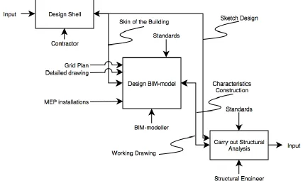
19 Figure 5 represents an IDEF0 workflow that would be the ideal situation. The different stages of a building projects are all connected to each other. Information can be easily be exchanged in both directions. This is not the case in the current workflow. As described in the interview with the engineer, his work entails an iterative process where changes are being made during the project. Because the lack of interoperability, iterations can result in a lot of time consuming and tedious work. In this research, a concept has been created that aims to improve the process of revisions by creating a new format to store data. In next section the concept will be explained.
Figure 5. IDEF0 ideal workflow
4.2. System Requirements
20
5.
CONCEPT STRUCTURAL ANALYSIS
This chapter introduces a concept that tries to solve the lack of interoperability between different software programs in a building process. In the first subsection the concept will be explained in detail. In the following subsections the concept has been created with the use of specific software. However, the concept is not restricted to the software used in this study and can be achieved with other software as well.
5.1. Proposed Method
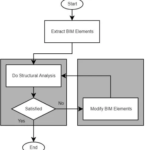
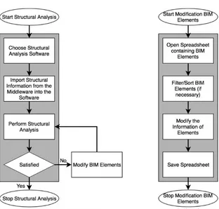
[image:21.595.179.419.329.575.2]In this concept, the necessary information for structural analysis is automatically extracted from the BIM model and structured in such a way that it can be easily used by structural analysis software. Additionally, the proposed method would allow the engineer to update the model based on the required changes in a semi-automated way. The general process of the concept is presented in Figure 6 where the two grey blocks represent the two different layers of development that are involved in this concept. The left layer represents (1) the interoperability with structural analysis software and the right layer (2) the modification of elements inside the BIM model. Both layers will be explained in the following subsections.
Figure 6. General Concept Structural Analysis Process
21 The next part of the concept involves a structural analysis (Figure 7). Part of the structural analysis is the analysis on the beam grid. Instead of drawing a 2D representation of the beam grid, it can be extracted from the BIM model which already contains the dimensions of the beam grid. The concept creates nodes and beams which connect to the nodes. With this information, a structural analysis can be carried out.
Figure 7. Flowchart Structural Analysis Figure 8. Flowchart Modication BIM Elements
22 5.2. Interoperability with Structural Analysis Software
Throughout this research I found that the exchange of information between the different disciplines in a building project can be improved. Engineers are creating new models from already existing models that are more filtered down than the original model, so it only contains the information they need to make calculations. Even though there are possibilities of extracting specific data from the original model, these possibilities are not used and sometimes not known.
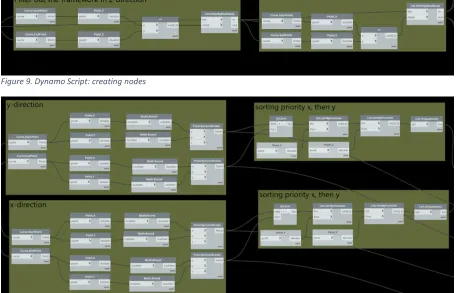
[image:23.595.70.526.344.637.2]In deliberation with the structural engineer at the company, another process has been created that fits the concept described in previous paragraph. The process entails the extraction of specific data from a BIM model to the data that is required for the structural analysis. The structural engineer is using Technosoft to specify and calculate the foundation of a building project. Therefore, in this research, Technosoft has been analysed to develop a tool. However, any calculation software that is accommodated with the ability of importing spreadsheets can be used. As for Technosoft, the software requires the x and y coordinates of nodes (i.e., joints) in a beam grid and are stored into a spreadsheet. Since the geometry of the beam grid already exists in the BIM model, this data can be extracted and manipulated with a Dynamo script.
Figure 9. Dynamo Script: creating nodes
Figure 10. Dynamo Script: sorting nodes
23 the two nodes it is connected to (Figure 11). The list of nodes containing the coordinates and the list of beams containing the node numbers can be copy pasted into Technosoft which will automatically draw the structure of the beam grid.
Figure 11. List of Beams
Currently, the engineer is redrawing the grid in Technosoft manually. With this tool it is possible to use the spreadsheets to import the beam structure. This will save time, especially when the project contains a lot of elements.
5.3. Modification in Spreadsheet
During the design phase of a project modifications in the structure of the building are likely to occur. Modifications made during the process result in rework and take up more time than necessary. Too reduce this amount of time, a concept has been created. In this research the concept is realized with Dynamo, collaborating with Revit and Excel. The visual script created in Dynamo is able to read information of the structural elements present in the BIM model and stores its relevant information in a spreadsheet (in this case Excel). Figure 12 shows how the parameters from each element is derived.
24 When all modifications are finished, the data in the spreadsheet can be imported to the BIM model. All modifications that have been made in the spreadsheet will then be applied. An example of an adjustment could be changing all columns on the top floor in grid A to columns with a smaller thickness. Figure 13 presents on the top left corner the row of columns that needs adjustment. The top right corner shows that these columns have a thickness of 450mm in the BIM model. By changing this value to another possible value (e.g., 300mm) in Excel (bottom left corner) and running the Dynamo script, the bottom right corner shows that the columns have been adjusted to 300mm in the BIM model.
25
6.
VERIFICATION & VALIDATION
To verify if the developed concept is working consistently and properly, the concept has been tested on other BIM models than the initial model that has been used to develop the concept. The BIM models are originated from the client. The projects consist of steel and concrete constructions or a combination of both. The concept should provide the same format of data as the initial model to verify its compatibility. Thereafter, the tools are validated. Due to the short amount of time, the validation of the tools is based on a discussion that took place in a workshop I provided for the employees. In this workshop the tool has been presented and explained to the employees involved with the BIM process. Afterwards the employees have been asked to take part in a survey to provide their own feedback on the developed concept.
6.1. Verification Concept
An important part of the tool is extracting the right data from the BIM model. Therefore, the script uses parameter names that are used in Revit. It is important that the names of the parameters are consistent in all projects. If not, the parameter names should be changed manually. Otherwise warnings will show up and the tool will fail to execute. Therefore, it is required to use the same parameter names throughout all projects to prevent necessary adjustments to the script. Considering that the parameter names are consistent, the tool provides the results that it is intended to provide.
The first BIM model is a concrete building. Within this project there are no structural columns nor structural framing elements present which results in the Dynamo script not being able the read the data that it wants to read. However, the interoperability process is generating coordinates for the nodes and some beams that connect the nodes.
The second BIM model tested is a combination of steel and concrete. The extraction of the structural columns has been executed, however with a minor bug caused by the difference in
[image:26.595.120.523.580.701.2]the naming of the ‘Column Location Mark’ parameter (CLM). The left row of Table 3 shows the format of the parameter that has been present in the initial model, the right row shows the second BIM model. The Dynamo script splits the cell based on a dash. Because the CLM of the second BIM model has two dashes (and sometimes even three) it causes disruption in the spreadsheet created. The numbers between parentheses describe the distance from the nearest grid line. These are not relevant for the use of this concept. To solve this issue the Dynamo script needs to be adjusted.
Table 3. Different Column Location Mark formats
Ideal Column Location Mark Format Disruptive Column Location Mark Format
Column Location Mark : A-1 Column Location Mark : B-1 Column Location Mark : C-1 Column Location Mark : D-1 Column Location Mark : E-1 Column Location Mark : F-1 Column Location Mark : G-1
26 As for the structural framing, the Dynamo script was not able to find this in the model. This is not a problem in the script but an issue that is due because of different naming. Instead of
using ‘Structural Framing’, ‘Structural Framing (Girder) is used in the BIM model. This issue does not occur when generating the nodes and the beam grid. These have been formatted reasonably well. However, because the second BIM model contains more levels, the beams have overlap which causes ambiguity in the structural analysis software. This is something that needs investigating. (See Figure 16 in Appendix III)
The third BIM model is construction which only contains steel and is a relatively simplistic construction. Again, CLM has not been transferred correctly and because of multiple levels the beams have overlap in the structural analysis software. It also appears that some beams are not connected to the nodes correctly. This could be solved by changing the level of accuracy in Dynamo. Nevertheless, this model has been able to extract most of the data correctly.
The fourth BIM model has a construction that is mainly concrete. Unfortunately, the same issue as the first BIM model occurs which is due to a different type of creating the BIM model.
6.2. Validation Concept
Due to the fact that the model is not yet ready to be used in the daily process of the client, and the lack of time to finish the model of this concept, the validation of the model is based on a workshop I gave at the company with employees that were interested and had time to join. In this workshop I explained them how the concept works and how to use it. During the workshop they were able to ask question, give feedback or start a discussion. Based on the workshop I created an online survey. The survey addressed the concept and the employees were asked to provide a score to each criterion mentioned in subsection 2.3. Since the transferability and the applicability are not something that the employees have been able to assess, they have been asked to provide feedback on the usability and the time efficiency of the model and to rate (1-5) these criteria compared to the current process of the client. The feedback is therefore based on the knowledge of the employees that they have gained throughout my time at the company and the workshop I gave.
Transferability
As noted from the verification of the model, there are some matters with the transferability of the current state of the model. Because of different parameter names used in projects, the model is not able to read the right information. The model should be changed to solve this issue. This however, is not a failure of the model, but something that needs to be kept in mind.
Usability
27 using in combination with Technosoft or any other software that uses this input for structural analysis.
Time efficiency
As for the time efficiency of the model, the employees also came to the average score of 3, whereas the two tools involved are both ranked differently. The employees mentioned that adjusting of structural elements within spreadsheets could save them a lot of time. However, the process of the integration with structural analysis software is not considered to achieve an improvement on time efficiency.
Applicability
The model does not make a difference in the type of structure that is used, both steel and concrete structures are tested, and the model should be able to produce the right results if
the ‘structural columns’ are being used in the BIM model which was not the case with the verification models. The model would be perfectly suitable for simplistic structures, rather a box designed building which consists of a beam grid with a flat surface.
28
7.
DISCUSSION
This section contains a critical analysis of the results established in the previous sections. Limitations and remarkable results are indicated and explained.
During the research I have gained the knowledge that it should be possible to export the beam grid from the Revit file into a DXF-file. The Technosoft software is able to import this DXF-file. This process could be more integrated than running Dynamo but requires knowledge on how to export and import the right information with the right settings. The engineer is not familiar with this process. However, the BIM modeller might be, which makes it interesting to have conversations about this and to develop agreements on how to implement this way of sharing information.
The verification of the model brought a few issues to light. The first issue (1) appeared in the Column Location Mark (CLM) of structural columns. Because some columns are not located on the grid lines that have been created in the BIM model, an additional number is added to the name of the CLM. This causes the columns (of the spreadsheet) to move to the right. This however is not a huge issue and can be ignored. The downside of this issue is that the data inside the format cannot be sorted on grid lines correctly and the first row (of the spreadsheet) is not matching with the data it contains and needs to be adjusted. A solution for this would be changing the Dynamo script so it generates the correct data in each column.
The other issue that appeared is (2) the overlap of beams in the beam grid. Because of multiple levels in a project and the structural analysis software being two dimensional, it results in having multiple beams between two nodes. A way to solve this would be adding a specific level as a constraint, so only elements on that level are gathered. Another option would be deleting the beams manually in the structural analysis software. This would take more time but might still be faster than drawing the whole beam grid manually.
Concluding from the used BIM models, the tool that has been designed has a few remarks. The tool gave proper results with steel structures. Yet, the tool has been created with the use of a sample file that contained a concrete structure. Apparently, the BIM models provided by the client did not contain any concrete columns or beams, but only concrete walls and floors. Therefore, those BIM models are not suitable to be used with this tool. Yet, the tool should be able to provide the right data for both concrete and steel structures.
A vital note to the tool is the importance of using the same parameter name throughout all projects. A different parameter name results in the tool not being able to extract the right data.
29
8.
CONCLUSION & RECOMMENDATIONS
This research has primarily investigated the current situation of structural analysis in BIM within the company and in the AEC industry. Thereafter it has focused on the more BIM enabled approaches that are also possible to adopt to. Besides, a new concept has been introduced which focusses on creating a middleware which allows BIM software and structural analysis software to collaborate and to make modifications outside of BIM. Considering the literature review, the interviews with employees and the design of a new concept, this research has established some results that are summarized in this section. To support this, the research questions are answered.
Main Question: “Which technique can be adopted by the client for the better integration of
structural analysis in their BIM process and workflow and how can this be integrated?”
Q1. Which BIM-compatible and BIM-supporting approaches/tools are available for structural analysis?
Q2. What is the current scope of BIM application at the company?
Q3. Which method is the client currently using for the structural analysis? Q4. Which approach/tool better fits the BIM workflow of the company? Q5. How can the company best adopt the identified approach/tool?
Starting with the Q1, in this research there are two approaches analysed with the use of literature. IFC is a file format that can be used to store specific information of a BIM model for different purposes (e.g. structural information). Many programs used in the AEC industry are able to work with IFC. However, IFC for structural engineering purposes is not as well developed as for MEP purposes for example. Another approach which integrates structural analysis with the BIM process is Robot for Revit. Robot is able to make a bidirectional link with the analytical model present in Revit. When in either of the two software programs changes are made, changes will be updated in both programs. However, the bidirectional link is limited to only one structural analysis software which is Robot. Both IFC and Robot require the BIM model to have a properly aligned analytical model. Which usually is not the case.
The current scope of BIM application at the company (Q2/Q3) has been analysed by interviews and observations. The client is working with different software programs for different purposes. The BIM modeller is mainly working with Revit and keeps the BIM model updated based on the input of other stakeholders. The structural engineer is not familiar with BIM at all. The engineer is used to working in different software programs. For example, Technosoft Raamwerk/Balkrooster and AxisVM is used for the structural analysis of the building. The information generated with this software is not included in the BIM model and is only present in separate files. With this approach comes a fair amount of rework, like redrawing the beam grid of a building. However, the dimensions of the beam grid are already present in the BIM model.
30 Adopting to Robot might also be interesting for the client. However, it is questionable what the consequences will be and if carrying out one structural analysis meets the requirements for the building projects the company is involved in. The use of Robot (and the other approaches) would require the BIM model to have proper alignment of the analytical lines in Revit. This is something that needs to be considered at earlier stages of the design process. Besides, using Robot would entail a totally different approach than the current one. The best way to adopt to Robot (Q5) would be starting to develop rules and guidelines for the architects/BIM modellers how to use the analytical model in Revit so time can be saved in a future stadium.
31
REFERENCES
[1] Autodesk Inc., "BIM," 2018. [Online]. Available:
https://www.autodesk.com/solutions/bim. [Accessed 11 April 2018].
[2] D. Bryde, M. Broquetas and J. M. Volm, "The project benefits of Building Information modelling (BIM)," Elsevier, 2012.
[3] R. Millman, “What is object oriented programming,” 10 7 2018. [Online]. Available:
http://www.itpro.co.uk/programming-languages/30204/what-is-object-oriented-programming.
[4] S. Azhar, "Building Information Modeling (BIM): Trends, Benefits, Risks, and Challenges for the AEC Industry," Leadership and Management in Engineering, 2011.
[5] M. Ball, 11 April 2018. [Online]. Available:
https://www.autodesk.com/redshift/building-information-modeling-top-11-benefits-of-bim/.
[6] Schreuders, 2011. [Online]. Available: http://www.schreuders.nl/bim.html. [7] "Learn: Dynamo," 2016. [Online]. Available: http://dynamobim.org/learn/. [8] Beelen CS architecten bv, "Ontwerpproces," 2018. [Online]. Available:
http://www.beelencs.nl/diensten/ontwerpproces/.
[9] J. Kunz and B. Gilligan, “Values from VDC/BIM use,” 2007. [Online]. Available:
http://cife.stanford.edu/VDCsurvey .pdf.
[10] R. G. Kreider and J. I. Messner, "The Uses of BIM," Creative Commons, San Francisco, 2013.
[11] S. P. Zotkin, E. V. Ignatova and I. A. Zotkina, “The Organization of Autodesk Revit Software Interaction with Applications for Structural Analysis,” Elsevier, 2016.
[12] Y. Arayici, T. Fernando, V. Munoz and M. Bassanino, "Interoperability specification development for integrated BIM use in performance based design," Elsevier, 2017. [13] D. Smith and M. Tardiff, “Building Information Modelling: A Strategic Implementation
Guide for Architects, Engineers, Constructors, and Real Estate Asset Managers,” John
Wiley & Sons, New Jersey, 2009.
[14] W. Jeong and K. Kim, “A performance evaluation of the BIM-based object-oriented physical modelling technique for building thermal simulations: a comparative case
study,” Sustainability 8, 2016.
[15] M. Weise, T. Liebech and J. Wix, “Integrating use case definitions for IFC developments,” Taylor & Francis, London, 2009.
[16] Y. Bahar, C. Pere, J. Landrieu and C. Nicolle, “A thermal simulation tool for building and
its interoperability through the Building Information Modelling (BIM) platform,”
Buildings, 2013.
[17] H.-L. Chi, X. Wang and Y. Jiao, "BIM-Enabled Structural Design: Impacts and Future Developments in Structural Modelling, Analysis and Optimisation Processes," CIMNE, Barcelona, 2014.
[18] Z.-Z. Hu, X.-Y. Zhang, H.-W. Wang and M. Kassem, “Improving interoperability between
32 [19] I. J. Ramaji and A. M. Memari, “Interpretation of structural analytical models from the
coordination view in building information models,” Elsevier, 2018.
[20] BuildingSMART International Ltd., “IFC View Defintion,” 2018. [Online]. Available:
http://www.buildingsmart-tech.org/specifications/ifc-view-definition. [21] KUBUS BV, “BIMcollab,” 2018. [Online]. Available:
https://www.bimcollab.com/en/BIM/OpenBIM/BCF.
[22] S. K. Singh, “Investigating the Current State of Industry Foundation Classes in the
Construction Industry,” Texas A&M University, 2016.
[23] A. Inc., “Revit - Robot Integration,” 2018. [Online]. Available:
http://help.autodesk.com/view/RVT/2019/ENU/?guid=GUID-B850E0C3-2314-4FEC-B5D1-A7C0CBDF290F.
[24] A. K. Nielsen and S. Madsen, “Structural modelling and analysis using BIM tools,”
Aalborg University, Aalborg, 2010.
[25] Het Nationaal BIM Platform, "Level of Detail: Het Nationaal BIM Platform," 2010. [Online]. Available: https://hetnationaalbimplatform.nl/.
33
APPENDICES
I.
Manual: Modification in Spreadsheet
The Dynamo script is capable of reading the structural information present in the BIM model. This information is written to an Excel file.
Process 1 – Step-by-step:
1. Open BIM model in Revit
2. Start Dynamo and open ‘Export_Excel.dyn’ (Manage ribbon)
3. Create an Excel file on your computer, go back to Dynamo to select the path of the file 4. Run Dynamo script (bottom left)
5. Data has been stored in the Excel file and will open automatically. The file contains all the structural columns present in the BIM model and contains a database of all the Families, Types and Materials that are loaded into the model.
Recommended (optional):
6. Create Filters in Excel to make it easier to select specific parameters (e.g., filter columns located on the first floor) – [ctrl]-A and look for ‘Filter’ in
the start ribbon
7. Additionally, the database in the other sheet can be used to create drop-down lists to make it more user friendly to choose values – Select a
column and look for ‘Data validation’ in the data
ribbon
These adjustments only need to be done once after exporting to Excel. The optional steps require a little bit of skills but are easy to learn and overall process speed will increase once you are familiar with the procedure. Now the structural engineer can make adjustment in to the structural columns in Excel without opening the BIM model. When the adjustments are final, the Excel file is used to make changes to the structural columns in the BIM model.
Process 2 – Step-by-step:
1. Open BIM model in Revit
2. Start Dynamo and open ‘Import_Excel.dyn’
3. Select the path of the file
4. Run Dynamo script (bottom left)
5. The columns will now update in the BIM model in Revit, as well as the rightest column in the Excel file that has not been updated yet.
[image:34.595.353.518.266.651.2]It is important to use the same parameter names. They may differ between different projects and therefore should always be checked before using the Dynamo script.
Figure 14. Filter
34
II.
Manual: Interoperability
The Dynamo script is capable of reading the structural information present in the BIM model. This information is written to an Excel file.
Process 1 – Step-by-step:
1. Open BIM model in Revit
2. Start Dynamo and open ‘Export_Excel.dyn’ (Manage ribbon)
3. Create an Excel file on your computer, go back to Dynamo to select the path of the file 4. Run Dynamo script (bottom left)
5. Data has been stored in the Excel file and will open automatically. The file contains all the locations of the nodes present in the BIM model and all the beams that connect the nodes.
Process 2 – Step-by-step: 1. Open Technosoft
35
[image:36.842.75.759.79.511.2]III.
Screenshots Technosoft
36
![Figure 2. Conversion of BIM model [18]](https://thumb-us.123doks.com/thumbv2/123dok_us/9689753.470333/14.595.76.520.167.253/figure-conversion-of-bim-model.webp)