How does one weakly electric fish locate and find another electric fish in its environment? One way is to orient to the electric discharges that the second fish produces using passive electrolocation. Passive electrolocation differs from active electrolocation in that the fish relies entirely upon exafferent rather than reafferent electrosensory information from its own electric discharge. By comparison with other sensory modalities, the physical cues available for passive electrolocation are limited. For example, there is no velocity cue that can be used for localization because electric signals are electrostatic fields, not propagating waves (Hopkins, 1986). In addition, most electric current sources in the fish’s environment are dipole-like so that the electric field vector is curved and does not point directly at the source. Even the magnitude of an electric field varies spatially in complex ways that make independent assessment of source distance and direction ambiguous.
Previous work has shown that mormyrid and gymnotiform
electric fish are very good at locating artificial electric signals in their environment. When a dipole electrode is introduced to a single resident fish in an aquarium and conspecific electric discharges are played through it, the resident typically makes a rapid, well-directed approach and attack on the electrode (Schluger and Hopkins, 1987; Davis and Hopkins, 1988; Hopkins, 1993b; Hopkins et al. 1996).
We have shown that these fish use a simple algorithm for finding these distant electrodes. They align their body with the local electric field and track the field until they reach the source. Tracking is accomplished by bending to turn the body in the direction of the local electric field vector and by adjusting the forward swimming velocity according to the error in the alignment with the electric field: speeding up when the error approaches zero, slowing down when it approaches +90 ° or −90 °. Although the resulting approach pathway is often longer than a direct approach, the fish’s strategy is a reliable one. Schluger and Hopkins (1987) first discovered electric-JEB0527
Gymnotiform electric fish are capable of locating and approaching an electrically discharging conspecific over a range of 1–2 m in a behavior called passive electrolocation. This paper investigates the movements of two species in experiments with approaches to stationary dipoles that are either silenced or jumped to a new direction during an approach.
Gymnotus carapo fail to find an electrode source in trials
in which the dipole electrode is switched off in mid-track. They slow their approach, become disoriented and drift away from the target within seconds of the field being switched off. This result suggests that the fish are unable to construct a cognitive map of a dipole source from brief exposure to local electrosensory stimuli.
The second set of trials shows that Brachyhypopomus
diazi and Gymnotus carapo bend their body to track electric
vectors which are suddenly jumped to a new direction. The latency of the bend response is 0.5 s after the jump. Bending initiates a turn that reduces to zero the error between the fish’s direction and the electric field vector and helps keep the fish aligned with the local electric field vector. Together, these experiments suggest that passive electrolocation is stimulus-bound and that these fish find the electrical sources simply by tracking instantaneous local electric current vectors.
Key words: passive electrolocation, electric fish, electroreception, orientation, gymnotiform fish, Brachyhypopomus diazi, Gymnotus
carapo, cognitive map, sensory motor integration.
Summary
Introduction
SHORT-RANGE ORIENTATION IN ELECTRIC FISH: AN EXPERIMENTAL STUDY
OF PASSIVE ELECTROLOCATION
KWANG-TZE SHIEH*, WILLARD WILSON†, MICHAEL WINSLOW‡, DON W. MCBRIDE JR§ ANDCARL D. HOPKINS¶
Section of Neurobiology and Behavior, 263 Seeley G. Mudd Hall, Cornell University, Ithaca, NY 14853, USA
Accepted 5 July 1996
*Present address: 3 Oakforest Drive, Ronkonkoma, NY 11779, USA.
†Present address: Department of Psychology, University of Maryland, College Park, MD 20742, USA. ‡Present address: 620 Pauline Avenue, Utica, NY 13500, USA.
field following in a mormyrid electric fish, Brienomyrus brachyistius. Subsequently, it was confirmed in the gymnotiform Gymnotus carapo by Davis and Hopkins (1988). Both of these studies used qualitative or semi-quantitative methods to analyse the tracking behavior. Hopkins et al. (1996) used quantitative methods for static and dynamic analysis of electric-field tracking behavior and made a study of responses to stationary as well as moving (rotating) electric sources.
In the present study, we modify the amplitude and direction of the electric field as the fish makes its approach. First, we test the fish’s ability to make an approach to an electrical source which is switched off in mid-track. We hoped to determine whether these fish were able to formulate some sort of computational image or cognitive map (Gallistel, 1989) of the source position from a brief exposure to electric fields at a distance. Scudamore and McGregor (1993) have implied that Gymnotus carapo is capable of generating some sort of image or map and of modifying its passive electrolocation strategy for different kinds of stimuli: plotting a direct trajectory when approaching a familiar stimulus waveform and a circular circumspect trajectory when approaching a novel, unknown stimulus. Our experiments are designed to explore further the possibility of a map image in these fish. Second, we record the track of a fish approaching an electric source which is suddenly jumped from one direction to another in mid-track. Like our previous studies with rotating electrodes (Hopkins et al. 1996), these experiments provide helpful insights into the dynamics of electric-field following and develop a new experimental paradigm for the study of passive electrolocation.
Materials and methods
The experimental methods have been described in detail in Hopkins et al. (1996) so only a brief account of the relevant details is given here.
Test fish
Three Gymnotus carapo (L.) (see Fig. 3) and two Brachyhypopomus diazi (Fernandez-Yepez, 1972) (see Fig. 6) were used in this study. Brachyhypopomus (formerly Hypopomus) diazi were collected near San Fernando, Venezuela, and were identified by J. P. Sullivan. We kept the fish in 40–200 l holding tanks on a 12 h:12 h L:D cycle and they were fed daily with Tubifex or black worms. Both species are aggressive after brief periods of isolation and attack experimental electrodes playing mimics of conspecific electric organ discharges (EODs) as if they were a territorial intruder.
Experimental tank
The experiments were conducted in a single circular arena with a diameter of 117 cm and depth of 20 cm. The water ranged in temperature from 26 to 28 °C and had a conductivity of 180µS cm−1. The tank was placed in a light-proof enclosure with an infrared-sensitive video camera attached to the ceiling over the tank to record the behavioral trials. The tank was illuminated with eight high-intensity infrared light-emitting
diodes (LEDs) placed around the lens of the camera. The tank floor was covered by a 3M Corporation ‘Scotchlite’ reflecting sheet that reflected the light from the LEDs back into the camera, so that the fish was visible as a silhouette against a light background. The symmetrical circular shape of the tank facilitated calculation of the electric field direction. A single shelter in the center of the tank served as the starting position for all trials.
Electrodes
We constructed chloridized silver-wire electrodes on 1 cm diameter plastic posts mounted vertically on the tank bottom. Positive and negative electrodes were separated by approximately 10 cm. The electrodes were positioned at least 10 cm from the wall of the tank and 9 cm from the bottom. Eight electrode pairs were positioned around the circumference of the experimental tank and one could be selected at random from a switch box.
For the second experiment, two quadrapole electrodes were set up on opposite sides of the circular tank. Each quadrapole was composed of two pairs of independently controlled dipoles, one defining the x-axis and the other, perpendicular to it, defining the y-axis. For each axis, the electrodes were 10 cm apart.
Behavioral trials
The behavioral trials were carried out during the first 3–4 h of the animal’s dark period. A dim red light could be turned on and off in the test arena to encourage the fish to return to a darkened shelter for the beginning of a trial. Each trial started when the fish was resting in the shelter and the red light was off. A stimulus was applied to a selected electrode located at the edge of the tank. When the stimulus was turned on, the fish was given 1 min to respond. A variable waiting period of 2–4 min elapsed between trials.
Approaches to silenced electrodes
For these experiments, we used simple dipole electrodes oriented tangentially to the tank boundary. All experiments were carried out with Gymnotus carapo; we played a 2 kHz single-period sine-wave stimulus triggered at a 63 Hz repetition rate to imitate the Gymnotus carapo EOD (see Fig. 3). When the fish crossed a line on the video screen halfway between the shelter and electrode, the stimulus to the electrode was switched off manually. We followed the fish’s trajectory for at least 5 s after switching off the stimulus.
Quadrapole electrodes, simulated angles and jump experiments
D/A converter of a 386-PC computer with a Lab Master analog input/output board. Each channel was isolated from ground by passing the signal through a 600Ω isolation transformer. The computer was programmed to output a digitized EOD waveform from a Gymnotus carapo (see Fig. 3) or Brachyhypopomus diazi (see Figs 5, 6) through the two D/A converters simultaneously, but the amplitude of the signal sent through to the x-axis pair was scaled by sinθwhile the signal through the y-axis pair was scaled by cosθwhere θ is the desired angle for the simulated dipole electrode axis (Fig. 1C–E). The EOD pulses were digitized at a sampling interval of 20µs per point. The EOD stimulus was repeated at 55 pulses s−1. The computer was fast enough to generate a
new set of output vectors for the two converters in mid-track and thus could jump the apparent direction of the dipole electrode during the fish’s approach. The field that the fish received jumped in direction by varying amounts depending on the fish’s location in the tank. Each field of the video was digitized in real time using a video framegrabber, and a number was written to the video screen indicating the simulated electrode angle (see below for calculations). The entire experiment was then recorded on sVHS video tape for later analysis.
The stimulus intensity was adjusted so that it was 0.22 mV cm−1 recorded at the center of the tank for the tangential electrode orientation (θ=0 °).
Electric field Body axis
β1 β2
In two-dimensional geometry: E ∝ 1 / r
b
Cylindrical dielectric
boundary P(r,θ)
r q
q′′ a
rd
d = a2/b rb
Point charge Image
charges:
q′ = q
q′′ = –q
q′
Quadrapole electrode
0 ° (tangential) +45 ° 90 ° (radial)
Computed current lines
A B
C D E
Tank boundary
50 cm Error ξ
F
E
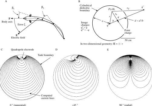
Fig. 1. (A) Top view of the fish showing the four points on the body digitized from the video image. The four points define three body segments. The fish bends its body to turn and the bend angles β1and β2are a measure of this response. The F vector defines the direction of the fish’s body segment, the E vector describes the local electric field direction at that same body segment. The error angle, ξ, is the angular difference between the axis of the F vector and the axis of the E vector, such that −π/2<ξ<π/2. Cartesian coordinates are used throughout. (B) Top view of the cylindrical tank in which the trials are conducted. The tank is 117 cm in diameter. To compute the direction of the electric field in the tank and to compensate for the effect of the circular non-conducting boundary, we used the method images. Two-dimensional geometry is assumed. The point charge, q, has two image charges: q″in the center of the tank, and q′at a distance, d, from the center. The tank has a radius a. The point charge, q, is at a distance, b, from the center of the tank, while the image charge, q′is located at a distance d (=a2/b) from this center. P(r,θ) is an arbitrary point in
space where an electric field is measured using polar coordinates. P is at a distance, r, from the center of the tank, a distance rbfrom charge q, and
a distance rdfrom image charge q′. In two-dimensional geometry, the electric field E generated by a point charge is proportional to 1/r (see Hopkins et al. 1996, for further details of calculations). (C–E) Electric-field lines computed for a quadrapole electrode composed of four mutually
[image:3.595.56.558.261.614.2]Video analysis
For all successful trials, we digitized the trajectory of the fish using the PEAK2D motion analysis software (Peak Performance Technology) running on an IBM 386 PC. Since the tank was over 1 m in diameter and only 20 cm deep and the fish’s movements were essentially restricted to 10 cm from the floor, analysis of the trajectory using a two-dimensional system was adequate.
We digitized one field every 1/6 s, skipping nine fields for every one stored by the frame grabber. Using a mouse to move a cursor across the digitized image, we recorded the x- and y-coordinates of the tip of the head, the mid part of the pectoral region, the mid part of the ‘pelvic’ region, and the tip of the tail (Fig. 1A) for each video field analysed.
Calculation of electric field directions
To determine the magnitude and the direction of the electric field within the circular arena, we used an analytical solution to the Laplace equation for electrostatics using the method of images (see Paul and Nasar, 1987, pp. 599–609). This method is described in Hopkins et al. (1996) and is summarized in Fig. 1B. Hopkins et al. (1996) show simulations of fields from tangential, 45 ° and radial dipoles. Fig. 1C,D,E presents simulations of the current paths from the quadrapole electrode generating simulated angles of 0 °, 45 ° and 90 °, respectively. These field lines are similar to those measured empirically from dipole sources (Schluger and Hopkins, 1987).
Error analysis
We calculated the direction of the electric field, E, at a point on the fish using the method described in Fig. 1B. The E vector direction in Fig. 1A varies between −π and +π. The body-axis vector, F, at the same point has an angular direction between −πand +π.The error angle, ξ, is defined as the acute angular difference between E and F for a given body segment; that is, the angular difference between the axis of the body and the axis of the electric field. Because of bimodal symmetry (Hopkins et al. 1996), we double all error angles, recenter on zero and divide by two, so that −π/2<ξ<π/2. Accordingly, if the electric-field axis points to the fish’s left as in Fig. 1A, the error is positive. In Hopkins et al. (1996), we first used the bimodal error angle which varies between −π and +π, but later converted to this monomodal error measure with −π/2<ξ<π/2 when we found that the fish was not as sensitive to the polarity of the electric field as to the direction of the axis.
Results
Approaching silenced electrodes
To what degree is passive electrolocation in fish stimulus-bound? To what degree can a fish localize an electrical source, compute a trajectory and make an approach without the need for continuous passive electrosensory feedback? We have previously established that electric fish are capable of precise
electric-field tracking in a situation in which they are allowed continuous sensory feedback from the stimulus during the course of their approach (Hopkins et al. 1996). The present results investigate how well electric fish can do when the stimulus is switched off during the approach trajectory.
In a series of preliminary trials, we turned the stimulus off as soon as the fish started to move from the shelter, but these fish quickly stopped moving and returned to cover. In order to encourage the fish to approach the electrode, we found it was necessary first to draw the fish out of the shelter by allowing it to approach the electrode at least halfway. We believed that this was a better test of their abilities to locate electrodes that had become silent.
We recorded 20 trials with one Gymnotus carapo and 80 trials using a second individual. All trials presented stimuli in the tangential orientation. The target electrodes were selected from one of the eight electrode pairs around the tank circumference using a random number table. Most trials lasted less than 15 s, and our analysis continued for at least 5 s after the electric field was turned off.
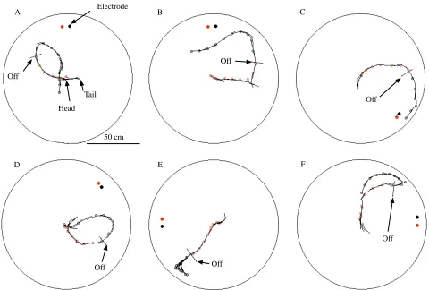
Fig. 2 shows the path taken by the fish in six typical trials in which the electrodes were turned off in mid approach. The ‘off’ line marks the point in each trajectory where the current to the electrodes was switched off. In all of these experiments, the fish appears to be making a normal circular approach to the electrodes, following the lines of the electric field as we have reported in previous published experiments (Davis and Hopkins, 1988). After the electrode is switched off, these fish appear to move more slowly, to reverse their direction or to turn in random directions. In only one of these examples (Fig. 2C) did the fish reach the electrodes.
Table 1 summarizes data for 80 trials in which we were able to collect at least 5 s of data after switching off the electrodes and compares these with 240 control trials for which the electric field was connected for the entire approach. These data show that the fish failed to find the electrode in 66 % of the experimental trials compared with 0 % in the control trials. In 34 % of the trials, the fish successfully found the silent electrode, although it appeared to be swimming around at random and not making precise directed approaches to it. In some cases, the fish’s successes were aided by the walls of the tank.
the stimulus was switched off. In control trials, fish approached electrodes successfully in either direction.
From these results, we conclude that this individual fails to find an electric-field source when it is silent even when given an opportunity to sample the electric field during a partial approach trajectory. When the stimulus ceases, the fish becomes disoriented within a few seconds. It stops swimming
in a directed way and either begins a random search pattern or loses interest entirely and returns to the shelter.
Approaches to simulated stimulus angles
In a previous study (Hopkins et al. 1996), we demonstrated a statistical correlation between non-zero error angles and subsequent corrective turning behavior by the fish. By measuring the cross correlation between the error angle of the electric field and the ‘bend’, β, of the body axis, we showed that the fish is likely to bend in the same direction as the electric field axis. This action reduces the error angle to zero and keeps the fish moving in the correct direction. The peak in the cross correlation occurs at a delay of 0.3–0.5 s. The goal of our next experiment was to develop a stimulus paradigm using quadrapole electrode geometry to simulate dipole angles artificially and to be able to jump from one dipole angle to another noiselessly and instantaneously as the fish is making its approach.
To test the reliability of our quadrapole electrodes in generating simulated dipole angles, we first generated stimuli at a number of simulated angles to investigate whether the fish
Electrode
Off
Off
Off
Off Off
Head Tail
Off
A B C
D E F
[image:5.595.63.543.96.420.2]50 cm
Fig. 2. Results from six experimental trials where the stimulus is switched off in mid approach. In each of these experiments, the fish starts the trial in a shelter located in the center of the tank. When the stimulus is turned on, with the electrodes oriented tangential to the boundary, the fish begins its approach. At the point indicated by the off line, the electric stimulus is switched off, and movement of the fish was monitored for another 5 s. The position of the fish’s head is indicated every 0.5 s by a red circle when the current is on and by a black circle when it is off; the body axis is given by a black line. The fish appear to be disoriented when the stimulus is turned off. In only one case (C) does the fish finally reach the electrode.
Table 1. Success rates of Gymnotus carapo in finding electrodes in trials in which the stimulus is switched off in
mid approach or left on for the entire approach
Stimulus switched Stimulus on for
off in mid track entire track
Number of fish 1 3
Number of trials 80 240
No response 0 11 (5 %)
Finds electrode 27 (34 %) 229 (95 %)
Fails to find electrode 53 (66 %) 0
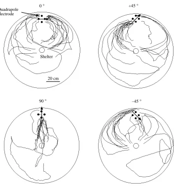
[image:5.595.47.298.645.729.2]approaches in the same way that it approaches a real dipole with a known angle. Fig. 4 shows the results for four different simulated angles: 0 °, 45 ° +90 ° and −45 °. At 0 °, the field lines spread out parallel to the tank boundary (see Fig. 1C) and the fish’s tracks appear to follow a similar pathway. At 90 °, the fish takes a direct approach along the radius of the tank, again
following the predicted path of the current lines (Fig. 1E). For the +45 ° and the −45 ° angles, the fish’s final approaches are tilted along the 45 ° axis, again resembling the field lines (Fig. 1D). These tracks are similar to previously published patterns with stationary dipoles in these four angular configurations (Hopkins et al. 1996), including the slight
Time (s) 30
0
–30
v
0
π/2
–π/2 0
Forward
Reverse
0 2 4
–2 –4
–6
ξ
1.0
6
r
Stimulus off
Forward Reverse
50 100
1 ms
Distance (cm)
A
B
C
[image:6.595.179.561.194.722.2]D Fig. 3. The behavior of an
individual Gymnotus carapo in experiments in which the stimulus was turned off in mid approach. Values are plotted before and after the time, t0,
when the stimulus is turned off. Eighty trials are superimposed for each scatterplot. Each grey dot represents data from a single video field. The fish and its EOD are shown at the top. (A) The dispersion of the error angles, plotted as average vector length,
r, calculated using circular
statistics (Batschelet, 1981). The
r value varies between 0 and 1.0,
approaching 1.0 when all of the angles converge on a single direction. The red line shows values when the fish is swimming forward (positive velocity), green values are for the fish swimming in reverse (negative velocity). (B)
ξ, the error angle between the fish’s head segment and the direction of the electric field at the head, varies between −π/2
and +π/2. Dots have been
dithered horizontally for visual clarity. The right half of the graph, where t>t0, shows the
error of the fish relative to the previously active electric field. (C) The distance between the head and the center of the electrodes. The dashed red lines shows the average values from all trials. This variable starts to decrease as the trial progresses, and this trend briefly continues after the stimulus is switched off, but then increases as the fish starts to wander away from the electrodes. (D) The velocity, v, of the fish parallel to its body axis. Red lines indicate the average values from all trials in which the fish is swimming forward (v>0 m s−1). The green
lines show averages for fields in which the fish was swimming in reverse (v<0 m s−1). The velocity increases as the fish approaches the electrode,
polarity preference. We conclude that the quadrapole is able accurately to generate simulated dipole angles that can reorient a fish’s approach path.
Simulated dipoles with jumps
Examination of the patterns of the current lines in Fig. 1C,D,E reveals that changes in the angle of the dipole axis may not greatly change the angle of the local electric field at a distance. Even for large changes in field direction close to the electrodes, there may be minimal changes in the field direction at the edge of the tank. To maximize the effect of a given jump at the position of the fish, we started each trial with a dipole axis pointing directly at the fish shelter, i.e. in the 90 ° configuration (Fig. 1E). Then, when we jumped the dipole axis by 45 ° in either direction from 90 °, we achieved significant jumps in E vector directions at the fish’s position. In these experiments, we moved the shelter and the two quadrapole electrodes to the vertices of an equilateral triangle within the tank in order to maximize the distance traveled while minimizing the effects of the tank walls. The vertices and shelter were located at least 27 cm from the walls of the tank. Brachyhypopomus diazi, which are slightly smaller than
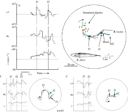
Gymnotus carapo and are slower swimmers, gave the best performance in these trials. We jumped the simulated electric dipole direction by +45 ° or −45 ° at intervals of approximately 1.2–1.5 s. The results of three such trials are shown in Fig. 5. We carried out 40 jump trials with one individual Brachyhypopomus diazi and 39 with two Gymnotus carapo individuals. In half of the trials, the simulated dipole angles were +45 ° jumps, in the remainder they were −45 ° jumps. Fig. 6 summarizes the results from the 40 trials with Brachyhypopomus diazi. The results have been divided into three columns representing cases where the error angle is negative (left column), zero (center) or positive (right) at the moment of the jump (t0, indicated by the dotted line in the center of each scatter plot).
The results are consistent with the observations presented for individual trials in Fig. 5. When the error changes to positive values, following a jump in field direction, the fish is likely to bend in the positive direction with a delay of 0.67 s (see arrow ‘b’ in Fig. 6). When the error angle becomes negative following a jump, the fish shows no response at the same delay (arrow ‘a’ in Fig. 6). When the error jump is zero (center column), the bend angle remains near zero. Velocity is unaffected by sudden error jumps in either direction.
0 ° +45 °
Shelter Quadrapole
electrode
[image:7.595.211.564.94.481.2]20 cm Fig. 4. Superimposed tracks of an
individual Gymnotus carapo
approaching a quadrapole electrode generating simulated dipole angles θ of 0 °, +45 °, 90 ° or −45 °. The quadrapole electrode is composed of one dipole pair defining the x-axis and another perpendicular pair defining the y-axis. The signal to the x-axis electrode pair is
x=EOD×sinθ, while the signal to the y-axis is y=EOD×cosθ, where EOD is a digitized EOD from a Gymnotus carapo. The simulated angle is indicated by an arrow on each plot. The fish’s approach paths (20 trials are superimposed for each electrode geometry) are oriented with respect to the simulated dipoles; in each case, the fish appears to be following the electric field lines (illustrated in Fig. 1).
A similar result is obtained for the 39 trials with Gymnotus carapo (Fig. 7), by computing the cross correlation, r(τ)=ξ(t)×β(t), between the error angle and the total bend angle for all jump trials, where r(τ) is defined as:
The correlation coefficient reaches a maximum at a delay of 0.33 s, indicating that the fish is most likely to turn in the same direction as the error after approximately this delay.
We conclude from these jump experiments that these fish respond to sudden changes in error angles by initiating a bend of the body which is designed to correct the error, reducing it
to nearly zero within 1 s. If the fish employs this error-correcting strategy in all of its approaches to current sources, it should be able to track the electric field accurately right up to a continuously discharging source, even if the source is moving or rotating.
Discussion
In passive electrolocation, a fish might be able to integrate information about the overall shape of the electric field that it is tracking, including information about changes in amplitude and the rate of changes of curvature of the electric-field lines. In theory, given certain assumptions about the dipole-nature of the source, such information could be integrated into a cognitive ∑[ξ(t)−ξ–]×[β(t +τ)− β−]
r(t) = .
∑[ξ(t)− ξ–]2× ∑[β(t)− β−]2
!
ξ
β
v (cm s
–1)
π/2
–π/2
π/2
–π/2 +40
–40
ww93
J1 J2
J1 Simulated dipoles
1 2 3
1
E vector
Tail Head
0 1 s
J1 J2
J1 J2 J3
ξ
β
v
ξ
β
v
Time A
B J1 J2 J3 C J1 J2
J2
20 cm
2 3
[image:8.595.98.514.97.462.2]B. diazi 1 ms
spatial map of the electric field which could allow the fish to make a prediction about the source position (Gallistel, 1989; Bennett, 1996). Since this is potentially important information to electric fish, it is not inconceivable that they might be able to make such a complex computation given the enormous brain areas that are devoted to electrosensory processing. Indeed, in a recent report, Scudamore and McGregor (1993) suggested that Gymnotus carapo select a direct approach path to an electrode when presented with a familiar EOD stimulus (a digitized EOD from a neighbor) and an indirect ‘cautious’ approach path when presented with an unusual stimulus (a single-period sine wave). If Scudamore and McGregor’s (1993) interpretation is correct, it implies that the fish has some mental image of the position of the electric source.
Our results from experiments in which the electrodes were silenced in mid approach do not support the cognitive-map hypothesis. Only 34 % of the fish arrived at the electrode, whereas 95 % did so in trials with continuous stimulation. Most of the fish slowed down and became disoriented with respect to the former electric-field direction; none showed any tendency to take a direct approach to the electrode.
It is possible that the motivation to approach the electrode is removed when the signal goes off. We have interpreted the
fish’s behavioral response to the electrodes as an aggressive defense of territory against a nonspecific intruder. The resident fish often charges the electrode, gives electrical threat signals, π/2
−π/2 π/2
−π/2 40
−40
β
ξ
Jump Jump
–π/2 < ξ(0) < –π/6 –π/6 < ξ(0) < π/6 π/6 < ξ(0) < π/2
0 1 s Time (t–t0)
Jump = t0
v (cm s
–1
)
B. diazi
G. carapo
Delay τ (s) –0.2
–0.1 0 0.1 0.2 0.3 0.4 0.5
–2 –1 0 1 2
r (
τ
[image:9.595.100.516.99.423.2]) r (τ) = ξ (t) ×β (t)
Fig. 6. Error angles, ξ, bend angles, β, and velocity, v, for 40 trials with Brachyhypopomus diazi and jumps in the simulated dipole axis of ±45 °. The time axes have been centered about the time of the jump in the simulated dipole axis (t0; vertical dotted line) and the results have
been separated into three columns according to the error angle at t=t0. Each dot shows a measurement for a single video field; the dots have
been dithered horizontally for visual clarity. The means ±S.E.M. are indicated by solid red and grey lines, respectively.
Fig. 7. Results of 40 jump experiments with Gymnotus carapo showing the cross correlation, r(τ)=ξ(t)×β(t), between the error angle,
[image:9.595.321.563.545.686.2]and bites the wires (Davis and Hopkins, 1988). We might logically expect, therefore, that a territorial fish would return to the shelter once an intruder had gone away. However, the results of the second experiment also suggest that the fish does not develop and interpret a cognitive map and that, in these trials, motivation is not an issue. Although the electrode remains in precisely the same place, the fish responds to the change in field angle by heading off in a new direction; such a result is not consistent with the hypothesis that the fish has developed a map of the position of the stimulus in space.
In the jump experiments, the fish begins its approach by aligning its body axis parallel to the electric-field lines, as expected from previous results (Davis and Hopkins, 1988; Hopkins, 1993a; Hopkins et al. 1996). When the electric field jumps to a new direction, the fish usually makes a rapid correction, bending its body axis and making a turn in the direction that reduces the error angle back to zero. The response to the jump takes 0.67 s, which is close to the 0.33 s delay observed in the cross correlation between error angle and bend angle in normal, non-experimentally manipulated approach trials. If the fish had been able to compute the position of the source, we might have expected it to depart from the new set of electric-field lines and make a more direct approach, especially in cases where the jumped electric field takes the fish on a long and indirect pathway (e.g. Fig. 5B). All of this evidence suggests that the fish is incapable of predicting the distance and direction of the source and that its approach strategy is simply based upon following the direction of the local electric field until it reaches the source. Hopkins et al. (1996) reached the same conclusion after conducting an experiment in which fish approached the same electrode over 100 times in sequence but did not show any learned ability to depart from the long circular field lines in order to make a more direct approach.
These conclusions contrast with those reached by Scudamore and McGregor (1993), who also worked with Gymnotus carapo. They suggest that Gymnotus carapo makes a more direct approach to an electrode when the stimulus is a familiar one, such as a neighbor’s EOD, and a less direct or ‘circumspect’ approach to an electrode transmitting a novel stimulus. Their conclusion implies that the fish has already generated a cognitive map of the location of the signaler. We are unable to reconcile the differences in the conclusions of these two studies, but we note that Scudamore and McGregor (1993) only measured one angle of departure from the shelter in order to characterize the entire trajectory of the fish while we used the entire track. Also, they used between one and five trials per stimulus per fish, while we were able to repeat a stimulus 40–80 times with no significant change in response behavior. Finally, Scudamore and McGregor (1993) carried out a systematic study comparing the responses to familiar and unfamiliar stimuli, while we did not. We investigated responses to stimulus waveforms only in our preliminary qualitative experiments, but found no differences and therefore did not proceed further. We do note significant variability in the initial departure directions of our fish under all stimulus conditions, owing presumably to the random orientation of the fish in the shelter relative to the electrodes, but
this initial randomness quickly converges on a track that is aligned with the electric-field vector (Fig. 3). We have also casually noted differences in the latency of a response, the speed of swimming and the probability of a response, dependent upon the amplitude of a stimulus, but we interpret this to be a reflection of a change in the motivation to attack rather than a change in the electrolocation mechanism. We did not observe a difference in the trajectory under these conditions once the fish had started its approach. If Scudamore and McGregor (1993) had compared the entire tracks of fish approaching familiar and novel stimuli, computed the directions of the electric fields in their tank and if their sample sizes had been sufficient to compare samples with high variability at the start, our conclusions might have been more consistent.
In the more natural situation in which one electric fish approaches another, there are additional physical cues that might be used by receivers. Rasnow et al. (1993), by making precise measurements of electric fields around gymnotiform fish, showed that the EOD travels rapidly from one end of the fish to the other during each EOD cycle, so that the axis of the vector recorded outside the fish wobbles back and forth about a mean direction within each EOD. This is true for wave-discharging species and pulse-discharging species such as Gymnotus carapo and Brachyhypopomus diazi (Caputi et al. 1989; Caputi and Budelli, 1993; Stoddard et al. 1995). As yet, there is no experimental evidence to suggest that a fish is sensitive to this wobble in the electric-field vector, which is likely to be small at a distance from the discharging fish. Most electroreceptors fire a single spike in response to an external pulsed EOD and, for these systems, it is unlikely that the fish would encode information about changes in vector directions within a single pulse.
When a fish gets close to another electric fish, it may get additional information about the location of the source by the position of ‘hot spots’ of electric current on the skin. This may permit a fish that is within a body length of a source to lunge at the source and ignore the electric field lines. Hopkins et al. (1996) report that error alignment deteriorates close to the electric field source.
Two types of electroreceptors encode information about the electric-field vector: pulse markers and burst duration coders. Ampullary electroreceptors are probably not involved in passive electrolocation of EODs since their frequency response is restricted to frequencies below 100 Hz, at which there is little energy in these EOD stimuli. Both receptor classes are directional (McKibben et al. 1993; Yager and Hopkins, 1993), but the directionality appears to derive from the path of current flow through the skin not from some directional characteristic of the receptor itself.
electrolocation to relate electrosensory experience in passive electrolocation to the control of motor output.
List of abbreviations
a the radius of the experimental tank
b distance of a point charge, q, from the center of the experimental tank
d distance of an image charge, q′′, from the center of the experimental tank
EOD electric organ discharge
E electric field vector
F fish body axis vector
ξ error angle between the axes of the E and F vectors (−π/2<ξ<+π/2)
β total bend angle of the fish’s body axis: the sum of two angles between head and mid segments and between mid and tail segments
P(r,θ) point of voltage measurement in a tank, in polar coordinates
q point charge used in computing electrostatic field direction
q′, q′′ image charges used in computing electrostatic field direction
r mean vector length resulting from computation of average error angle using circular statistics; used as a measure of angular dispersion
r(τ) cross correlation, a function of delay time, τ rd distance from the image charge, q′, to the point of
voltage measurement, P
rb distance from the point charge to the position of voltage measurement, P
t time
t0 time when the simulated dipole angle changes direction
θ desired angle for the simulated dipole electrode axis. v velocity (m s−1) of the fish parallel to F
This research was supported by a grant from the National Science Foundation (BNS-8810080), by funds from the New York State Hatch Act (191426), a Research Experience for Undergraduates grant from NSF to K.W.S. a Pew Charitable Trust Fund summer fellowship to M.W. and by funds from NIMH grant MH37972 to C.D.H. We thank Garry Harned for excellent technical assistance throughout and Matthew Friedman for comments on the manuscript.
References
BASTIAN, J. (1982). Vision and electroreception: Integration of
sensory information in the optic tectum of the weakly electric fish
Apteronotus albifrons. J. comp. Physiol. A 147, 287–297.
BATSCHELET, E. (1981). Circular Statistics in Biology. London:
Academic Press.
BENNETT, A. T. D. (1996). Do animals have cognitive maps? J. exp.
Biol. 199, 219–224.
CAPUTI, A. ANDBUDELLI, R. (1993). A realistic model of the electric
organ discharge (EOD) of Gymnotus carapo. J. comp. Physiol. A 173, 751.
CAPUTI, A., MACADAR, O. AND TRUJILLO-CENOZ, O. (1989).
Waveform generation of the electric organ discharge in Gymnotus
carapo. III. Analysis of the fish body as an electric source. J. comp. Physiol. A 65, 361–370.
DAVIS, E. A. AND HOPKINS, C. D. (1988). Behavioural analysis of electric signal localization in the electric fish, Gymnotus carapo, Gymnotiformes. Anim. Behav. 36, 1658–1671.
FERNANDEZ-YEPEZ, A. (1972). Analisis ictiologico del complejo
Hidrografico (D4) ‘Rio Yaracuy’. In Direccion de Obras
Hidraulicas, Republica de Venezuela, 25pp, 40 plates. Caracas,
Venezuela: Ministerio de Obras Publicas.
GALLISTEL, C. R. (1989). Animal cognition, the representation of
space, time and number. A. Rev. Psychol. 40, 155–189.
HARTLINE, P. H., KASS, L. AND LOOP, M. S. (1978). Merging of
modalities in the optic tectum: Infrared and visual integration in rattlesnakes. Science 199, 56–59.
HOPKINS, C. D. (1986). Temporal structure of non-propagated electric
communication signals. Brain Behav. Evol. 28, 43–59.
HOPKINS, C. D. (1993a). Behavioral analysis of sensory function:
active and passive electrolocation. J. comp. Physiol. A 173, 688.
HOPKINS, C. D. (1993b). Neuroethology of passive electrolocation. J.
comp. Physiol. A 173, 689–695.
HOPKINS, C. D., SHIEH, K.-T. ANDMCBRIDE, D. (1996). A quantitative
analysis of passive electrolocation behavior in electric fish. Brain
Behav. Evol. (in press).
KNUDSEN, E. I. (1976). Midbrain responses to electroreceptive input
in catfish: evidence for orientation preferences and somatotopic organization. J. comp. Physiol. A 109, 51–67.
KNUDSEN, E. I. (1982). Auditory and visual maps of space in the optic
tectum of the owl. J. Neurosci. 2, 1177–1194.
KNUDSEN, E. I., KNUDSEN, P. K. AND MASINO, T. (1993). Parallel
pathways mediating both sound localization and gaze control in the forebrain and midbrain of the barn owl. J. Neurosci. 13, 2837–2852.
MCKIBBEN, J. R., HOPKINS, C. D. ANDYAGER, D. Y. (1993). Directional
sensitivity of tuberous electroreceptors: polarity preferences and frequency tuning. J. comp. Physiol. A 173, 415–424.
PAUL, C. R. AND NASAR, S. A. (1987). Introduction to
Electromagnetic Fields. New York: McGraw-Hill.
RASNOW, B., ASSAD, C. ANDBOWER, J. M. (1993). Phase and amplitude
maps of the electric organ discharge of the weakly electric fish,
Apteronotus albifrons. J. comp. Physiol. A 172, 481–491.
SCHLUGER, J. AND HOPKINS, C. D. (1987). Electric fish approach
stationary signal sources by following electric current lines. J. exp.
Biol. 130, 359–367.
SCUDAMORE, R. E. ANDMCGREGOR, P. K. (1993). Approach paths of
electric fish to an active electrode are affected by playback stimulus. Anim. Behav. 46, 1240–1242.
SPARKS, D. L. (1986). Translation of sensory signals into commands
for control of saccadic eye movements: role of primate superior colliculus. Physiol. Rev. 66, 118–171.
STODDARD, P. K., RASNOW, B. ANDASSAD, C. (1995). Electric organ
discharge of the gymnotiform electric fish Brachyhypopomus spp. In Nervous Systems and Behaviour: Fourth International Congress
of Neuroethology, vol. 4 (ed. M. Burrows, T. Matheson, P.
Newland and H. Schuppe), pp. 417. Cambridge, England: Georg Thieme Verlag.

![Fig. 7. Results of 40 jump experiments with Gymnotus carapotwo measures. A significant positive correlation between bend anderror [positive r(produce positive bends while negative errors produce negative bends.ξshowing the cross correlation, r(τ)=ξ(t)×β(t), between the error angle,, and the bend angle, β, plotted against the delay τ (in s) between theτ) values] indicates that positive errors tend toThe peak cross correlation occurs at a delay of approximately 0.33 s.](https://thumb-us.123doks.com/thumbv2/123dok_us/1156498.637075/9.595.100.516.99.423/experiments-gymnotus-signicant-correlation-correlation-indicates-correlation-approximately.webp)
