973
©IJRASET: All Rights are Reserved
Designing of Thermal Expansion in Rectangular
Geometry using Different Materials with Analysis
Ajay Malik1, Miss. Archana2 1
M.Tech Scholar ECE DPG ITM
2
Assit. Prof. ECE dept. DPG ITM
Abstract: A MEMS thermal actuator is a micromechanical device that naturally produces movement by thermal expansion. In this article we have measured the thermal expansion of various structural materials of thermal actuator and executed utilizing COMSOL. When we utilize SU8 as structural material with 298K as outside temperature, then the greatest temperature is 41 µm for the geometry that is quite high in comparison to different materials. So we conclude by this paper that by utilizing SU8 as structural materials we can get high state of displacement in warm actuators.
Keywords: MEMS, FEM, COMSOL, THERMAL EXPENSION, 3D
I. INTRODUCTION
Various sorts of small scale actuators have risen lately. Every sort of actuators has its own particular novel advantages, for example, giving extensive power, devouring less power, offering long relocation, and holding lofty actuating speed. However, none of them could carry all advantages, in fact, some trade-offs exist between these advantages. An actuator is one that actuates or moves something. More particularly, an actuator is a gadget that coverts energy into movement or mechanical energy. A thermal actuator converts small amount of thermal expansion of one part of the device translates to a large amount of deflection of the overall device. Generally created out of doped Single Crystal Silicon or Poly silicon as a complex agreeable part, by utilizing diverse materials we will endeavor to produce more deflection in the device.
II. DESIGN AND ANALYSIS
Thermal extension is the sort of actuator i.e. when we change temperature the material grows. In this paper we have outlined and investigated three distinct geometries they are rectangular, triangular and U-shape.
A. Designing Rectangular Shape
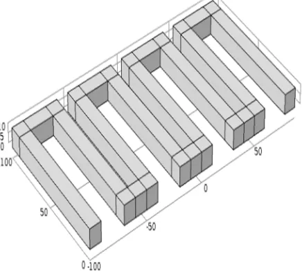
[image:1.612.209.427.517.713.2]Rectangular shape comprise of eight straight rectangles in parallel with measurement of 10µm, 110µm, 10 µm width, length and height separately. With a gap of 20 µm and 10 µm between alternating rectangles as shown in figure 1.
974
©IJRASET: All Rights are Reserved
[image:2.612.184.420.130.258.2]By applying fixed boundaries to lower base of the rectangle so that the expansion only takes place in upwards direction. The region is shown in figure 2 colored grey. The remaining region shown as blue where heat flows can take place.
Figure 2: Fixed boundaries (lower base)
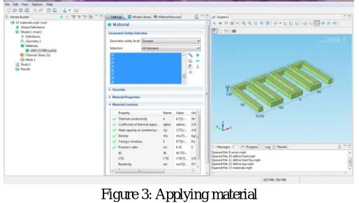
Figure 3 indicates applying of structural materials to the geometries found in green shading. A copper beryllium composite is connected to the device to analyze the thermal extension of the geometry. The thermal stress physics is applied to the device to analyze displacement of the device due to thermal expansion of device.
[image:2.612.178.435.380.525.2]The heat flux is given conduction only. The heat source is a constant heat source of 1*108 W/m3. The air cooling at the limits is communicated utilizing a consistent warmth exchange coefficient of 7000 W/m2 and a surrounding temperature of 298 K. The articulation for warm development requires strain reference temperature for the copper beryllium compound, which for this situation is 293 K. [6]
Figure 3: Applying material
[image:2.612.189.425.592.724.2]Figure 4 shows the meshed geometry. Mesh generation is one of the most critical aspects of engineering simulation. Too many cells may result in long solver runs, and too few may lead to inaccurate results. COMSOL Meshing innovation gives a way to adjust these prerequisites and acquire the correct work for every recreation in the most robotized way possible
975
©IJRASET: All Rights are Reserved
III. RESULTS
When we utilize 298K as outer temperature then the greatest displacement is 0.0453 µm for the geometry. The accompanying figure 5 demonstrates the aggregate displacement in the device utilizing copper beryllium amalgam
Figure5: Displacement of the Device
The accompanying figure demonstrates the displacement of a bend that takes after the top inward edges of the device from left to right
Figure6: Displacement vs Position graph
976
©IJRASET: All Rights are Reserved
Figure7: Displacement of the Device
The following figure shows the displacement of a curve that follows the top inner edges of the device from left to right.
Figure8: Displacement vs Position graph
When we use 298K as external temperature then the maximum displacement is 0.0642 µm for the geomtry. The following figure 9 shows the total displacement in the device using aluminum.
977
©IJRASET: All Rights are Reserved
The following figure shows the displacement of a curve that follows the top inner edges of the device from left to right.
Figure10: Displacement vs Position graph
When we use 298K as external temperature then the maximum displacement is 0.0709 µm for the geomtry. The following figure 11 shows the total displacement in the device using magnesium.
Figure11: Displacement of the Device
The following figure shows the displacement of a curve that follows the top inner edges of the device from left to right.
978
©IJRASET: All Rights are Reserved
When we use 298K as external temperature then the maximum displacement is 0.0812 µm for the geomtry. The following figure 13 shows the total displacement in the device using lead.
Figure13: Displacement of the Device
The following figure shows the displacement of a curve that follows the top inner edges of the device from left to right.
Figure14: Displacement vs Position graph
When we use 298K as external temperature then the maximum displacement is 41 µm for the geomtry. The following figure 15 shows the total displacement in the device using SU8.
979
©IJRASET: All Rights are Reserved
The following figure shows the displacement of a curve that follows the top inner edges of the device from left to right.
Figure16: Displacement vs Position graph
IV. CONCLUSION
It is concluded that when we utilize 298K as outside temperature and copper beryllium composite as strutral material then the most extreme displacement is 0.0453 µm for the geometry. When we utilize same outside temperature and poly silicon as structural material then the most extreme displacement in the device is 0.0071 µm. Again with same outside temperature and aluminum as strutral material then the greatest displacement in the gadget is 0.0642 µm. with same outside temperature and magnesium as strutral material then the most extreme displacement in the device is 0.0709 µm. When we utilize 298K as outer temperature then the most extreme displacement is 0.0812 µm for the device utilizing lead as structural material. When we employ SU8 as structural material with 298K as external temperature then the highest displacement is 41 µm for the geometry, wich is very lofty as compared to other materials. So we conclude that by using SU8 as strutural materials we can get high level of dispacement in thermal actuators.
REFERENCES
[1] Amita Chhabra, Jai Parkash and Anurag Singh, “A Study on Thermal Expansion Using Different Alloys for MEMS Actuators”, nternational Journal of
Research in Management, Science & Technology (E-ISSN: 2321-3264),Vol. 3, No. 2, April 2015.
[2] Rachita Shettar, Dr B G Sheeparamatti,” Modeling and Analysis of Thermal Bimorph Using COMSOL”COMSOL Conference in Bangalore, 2013.
[3] M Ataka and H. Fujita,“Micro Actuator array on a flexible sheet - smart mems sheet”, IEEE 26th International conference on micro electro mechanical systems
(mems), pp 536-539, January 2013.
[4] Jonas Henriksson, Maurizio Rosario Gullo, and Juergen Brugger,” Integrated Long RangeThermal Bimorph Actuators for Parallelizable Bio-AFM
Applications” Vol. 13, No. 8, August 2013.
[5] Peng Li, Yang Yang,” Experimental study on the thermal expansion coefficient of high strength/performance concrete at early ages”,Mechanic Automation and
Control Engineering (MACE), Second International Conference, pp. 3148-3151,2011.
[6] Zakri Ghazalli, Asnul HadiAhamad, Mohd Fazli Ismail, Khairul Fikri Muhamad “Design of Electrostatic Comb Actuators Based on Finite Element Method”