warwick.ac.uk/lib-publications
Original citation:
Wang, Jidai, Lu, Kunpeng, Ma, Lan, Wang, Jihong, Dooner, Mark, Miao, Shihong, Li, Jian and
Wang, Dan. (2017) Overview of compressed air energy storage and technology
development. Energies, 10 (7). 991.
Permanent WRAP URL:
http://wrap.warwick.ac.uk/91858
Copyright and reuse:
The Warwick Research Archive Portal (WRAP) makes this work of researchers of the
University of Warwick available open access under the following conditions.
This article is made available under the Creative Commons Attribution 4.0 International
license (CC BY 4.0) and may be reused according to the conditions of the license. For more
details see:
http://creativecommons.org/licenses/by/4.0/
A note on versions:
The version presented in WRAP is the published version, or, version of record, and may be
cited as it appears here.
energies
Review
Overview of Compressed Air Energy Storage and
Technology Development
Jidai Wang1,*, Kunpeng Lu1, Lan Ma1, Jihong Wang2,3 ID, Mark Dooner2, Shihong Miao3, Jian Li3and Dan Wang3,*
1 College of Mechanical and Electronic Engineering, Shandong University of Science and Technology,
Qingdao 266590, China; [email protected] (K.L.); [email protected] (L.M.) 2 School of Engineering, University of Warwick, West Midlands, Coventry CV47AL, UK;
[email protected] or [email protected] (J.W.); [email protected] (M.D.) 3 State Key Laboratory of Advanced Electromagnetic Engineering and Technology, School of Electrical and
Electronic Engineering, Huazhong University of Science and Technology, Wuhan 430074, China; [email protected] (S.M.); [email protected] (J.L.)
* Correspondence: [email protected] (J.W.); [email protected] (D.W.); Tel.: +86-158-5420-2209 (J.W.); +86-130-0619-0033 (D.W.)
Received: 18 May 2017; Accepted: 7 July 2017; Published: 13 July 2017
Abstract: With the increase of power generation from renewable energy sources and due to their intermittent nature, the power grid is facing the great challenge in maintaining the power network stability and reliability. To address the challenge, one of the options is to detach the power generation from consumption via energy storage. The intention of this paper is to give an overview of the current technology developments in compressed air energy storage (CAES) and the future direction of the technology development in this area. Compared with other energy storage technologies, CAES is proven to be a clean and sustainable type of energy storage with the unique features of high capacity and long-duration of the storage. Its scale and cost are similar to pumped hydroelectric storage (PHS), thus CAES has attracted much attention in recent years while further development for PHS is restricted by the availability of suitable geological locations. The paper presents the state-of-the-art of current CAES technology development, analyses the major technological barriers/weaknesses and proposes suggestions for future technology development. This paper should provide a useful reference for CAES technology research and development strategy.
Keywords:compressed air energy storage (CAES); renewable energy; energy storage
1. Introduction
How to maintain economic growth and at the same time reduce the usage of fossil fuel for environmental protection is a global challenge. Various efforts are being made, mainly in two aspects: to reduce the energy consumption by improving energy efficiency and to explore clean and sustainable renewable energy sources [1,2]. Wind, solar and other alternative energy sources are being explored and rapidly developed. Wind power is considered as one of the renewable energy sources with a great development potential in the 21st century. However, the high-level penetration of wind power generation in the grid causes serious problems of power grid stability and reliability due to the intermittence and volatility of wind power. Suitable solutions are urgently needed and energy storage has been recognized as one of the most promising technologies for addressing the problems [3,4].
Energy storage, especially PHS, has a long history of being used for grid dispatching and peak shaving. Coal and gas reserves were historically considered as the major storage forms for flexible dispatch of energy. As technology developed, various feasible energy storage technological solutions have emerged on the market. At the ENERGY STORAGE CHINA 2016 conference, the China Energy
Energies2017,10, 991 2 of 22
Storage Alliance reported that China had 118 energy storage projects in operation (employing Li-ion, lead-acid and flow batteries, and excluding PHS, CAES and thermal energy storage). This represents 105.5 MW of installed capacity with a 110% (2010–2015) annual growth rate, meaning a predicated capacity of up to 24.2 GW (excluding PHS) and 40 GW (including PHS) by 2020 [5].
[image:3.595.82.516.257.406.2]Energy storage can be organized into several categories based on the nature of its operation and storage medium used: primary fuel (such as coal, oil storage, etc.), intermediate fuel (such as gas, hydrogen, etc.), electrical energy storage and other forms [1]. The recent status of electrical energy storage technologies is presented in the Table1[6–10], and the cost of different energy storage technologies is shown in Figure 1[6–11], including the capital energy cost pitted against capital power cost.
Table 1.Technical characteristics of electrical energy technologies [6–10].
Technology Energy Density (Wh/L) Power Rating (MW) Suitable Storage Duration Lifetime (years) Discharge Time Cycling Times (cycles) Maturity
PHS 0.5–2 30–5000 H-Mon 40–60 1–24 H+ 10,000–30,000 Mature
Flywheel 20–80 0.1–20 Sec-Min 15–20 Sec-15 Min 20,000 Early Com
CAES 2–6 ≥300 H-Mon 20–40 1–24 H+ 8000–12,000 Early Com
Capacitor 2–6 0–0.05 Sec-H 1–10 Millis-1 H 50,000+ Com
SMES 0.2–6 0.1–10 Millis-H 20–30 ≥30 Min 10,000+ Demo/Early Com
TES 80–500 0.1–300 Min-Days 5–30 1–24 H+ - Demo/Early Com
Solar fuel 500–10,000 0–10 H-Mon - 1–24 H+ Developing
Hydrogen
fuel cell 500–3000 0–50 H-mon 5–20 Sec-24 H+ 1000+ Developing/Demo
Li-ion 150–500 0–100 Min-Days 5–15 Min-H 1000–10,000 Demo
Lead-acid 50–90 0–40 Min-Days 5–15 Sec-H 500–10,000 Mature
Abbreviations: SMES, Superconducting magnetic energy storage; TES, Thermal energy storage.
In more detail, a meticulous comparative life cycle cost (LCC) analysis of electricity storage systems was provided by Zakeri and Syri, and the LCC of a CAES plant is highly dependent on fuel costs, emissions costs, and charging electricity prices [11]. Comparing the investment cost, capacity, lifetime, energy density and storage duration, PHS and CAES are suitable for use in large-scale commercial applications where they are more economic [6–12].
Energies 2017, 10, 991 2 of 22
Storage Alliance reported that China had 118 energy storage projects in operation (employing Li-ion, lead-acid and flow batteries, and excluding PHS, CAES and thermal energy storage). This represents 105.5 MW of installed capacity with a 110% (2010–2015) annual growth rate, meaning a predicated capacity of up to 24.2 GW (excluding PHS) and 40 GW (including PHS) by 2020 [5].
[image:3.595.173.422.512.666.2]Energy storage can be organized into several categories based on the nature of its operation and storage medium used: primary fuel (such as coal, oil storage, etc.), intermediate fuel (such as gas, hydrogen, etc.), electrical energy storage and other forms [1]. The recent status of electrical energy storage technologies is presented in the Table 1 [6–10], and the cost of different energy storage technologies is shown in Figure 1 [6–11], including the capital energy cost pitted against capital power cost.
Table 1. Technical characteristics of electrical energy technologies [6–10].
Technology Energy Density (Wh/L) Power Rating (MW) Suitable Storage Duration Lifetime (years) Discharge Time Cycling
Times (cycles) Maturity
PHS 0.5–2 30–5000 H-Mon 40–60 1–24 H+ 10,000–30,000 Mature
Flywheel 20–80 0.1–20 Sec-Min 15–20 Sec-15 Min 20,000 Early Com
CAES 2–6 ≥300 H-Mon 20–40 1–24 H+ 8000–12,000 Early Com
Capacitor 2–6 0–0.05 Sec-H 1–10 Millis-1 H 50,000+ Com
SMES 0.2–6 0.1–10 Millis-H 20–30 ≥30 Min 10,000+ Demo/Early Com
TES 80–500 0.1–300 Min-Days 5–30 1–24 H+ - Demo/Early Com
Solar fuel 500–10,000 0–10 H-Mon - 1–24 H+ Developing
Hydrogen
fuel cell 500–3000 0–50 H-mon 5–20 Sec-24 H+ 1000+ Developing/Demo
Li-ion 150–500 0–100 Min-Days 5–15 Min-H 1000–10,000 Demo
Lead-acid 50–90 0–40 Min-Days 5–15 Sec-H 500–10,000 Mature
Abbreviations: SMES, Superconducting magnetic energy storage; TES, Thermal energy storage.
In more detail, a meticulous comparative life cycle cost (LCC) analysis of electricity storage systems was provided by Zakeri and Syri, and the LCC of a CAES plant is highly dependent on fuel costs, emissions costs, and charging electricity prices [11]. Comparing the investment cost, capacity, lifetime, energy density and storage duration, PHS and CAES are suitable for use in large-scale commercial applications where they are more economic [6–12].
TES
0 1000 10000
100 1000 10000 0 Capacitor Super Capacitor Flywheel SMES CAES PHS Fuel Cells Li-ion Lead acid
Capital Power Cost ($/kW)
C a p it a l E n er g y C o st ( $ /k W h )
Figure 1. Capital energy cost vs. capital power cost [6–10].
PHS, as shown in Figure 2, is one of the most widely-used energy storage technologies, which has demonstrated its merits in terms of technological maturity, high cycle efficiency, large rated power, long service life and low operating cost, but the location choices are highly restricted, construction cycles are long, maintenance costs are high and it impacts the local environment, so the further utilization of PHS is limited [13–15]. In addition to PHS, CAES is another feasible way to realize large-scale power storage. Since 1949 when Stal Laval proposed to store compressed air using
Figure 1.Capital energy cost vs. capital power cost [6–10].
Energies2017,10, 991 3 of 22
storage. Since 1949 when Stal Laval proposed to store compressed air using underground caverns, the research in CAES has been progressing [16]. Compared with PHS, CAES has relatively low impact on the environment and the cost of building a CAES plant is similar to the cost of PHS [4,15–19]. While PHS development has slowed down (or increased in difficulty), CAES has the potential to be an equivalent technology with its distinguishing advantages allowing it to take the place of PHS. Therefore, the article concentrates on the technology development and future trend in CAES.
2. Description of CAES Technologies
CAES refers to the energy stored in the form of high pressure compressed air and consumed in a different form of energy converted from the compressed air. In supporting power network operation, compressed air energy storage works by compressing air to high pressure using compressors during the periods of low electric energy demand and then the stored compressed air is released to drive an expander for electricity generation to meet high load demand during the peak time periods, as illustrated in Figure3.
Energies 2017, 10, 991 3 of 22
underground caverns, the research in CAES has been progressing [16]. Compared with PHS, CAES has relatively low impact on the environment and the cost of building a CAES plant is similar to the cost of PHS [4,15–19]. While PHS development has slowed down (or increased in difficulty), CAES has the potential to be an equivalent technology with its distinguishing advantages allowing it to take the place of PHS. Therefore, the article concentrates on the technology development and future trend in CAES.
2. Description of CAES Technologies
CAES refers to the energy stored in the form of high pressure compressed air and consumed in a different form of energy converted from the compressed air. In supporting power network operation, compressed air energy storage works by compressing air to high pressure using compressors during the periods of low electric energy demand and then the stored compressed air is released to drive an expander for electricity generation to meet high load demand during the peak time periods, as illustrated in Figure 3.
Higher Reservoir
Generator and Motor
Lower Reservoir
[image:4.595.184.414.292.439.2]Turbine and Pump
Figure 2. Pumped hydroelectric storage.
Compressed Air
Generator Motor
Figure 3. Illustration of a compressed air energy storage process.
[image:4.595.179.416.475.625.2]CAES technology is based on the principle of traditional gas turbine plants. As shown in Figure 4, a gas turbine plant, using air and gas as the working medium, mainly consists of three sections: gas turbine, compressor and combustor. Gas with high temperature and high pressure, which is formed by mixing compressed air and fuel in the combustion chamber, drives the turbine which in turn drives a generator to generate electricity [20,21]. For a CAES plant, as shown in Figure 5, there are two different stages of operation, namely compression and expansion. Since the two stages do not run simultaneously, there is higher system efficiency (48–54%) than in traditional gas turbine systems. At present, two large scale commercial CAES plants involving gas fires are in operation. The first CAES plant was installed and commissioned for operation in Huntorf, in 1978 [19]. It has a rated generation capacity of 290 MW for providing load following service and meeting the peak demand
Figure 2.Pumped hydroelectric storage.
Energies 2017, 10, 991 3 of 22
underground caverns, the research in CAES has been progressing [16]. Compared with PHS, CAES has relatively low impact on the environment and the cost of building a CAES plant is similar to the cost of PHS [4,15–19]. While PHS development has slowed down (or increased in difficulty), CAES has the potential to be an equivalent technology with its distinguishing advantages allowing it to take the place of PHS. Therefore, the article concentrates on the technology development and future trend in CAES.
2. Description of CAES Technologies
CAES refers to the energy stored in the form of high pressure compressed air and consumed in a different form of energy converted from the compressed air. In supporting power network operation, compressed air energy storage works by compressing air to high pressure using compressors during the periods of low electric energy demand and then the stored compressed air is released to drive an expander for electricity generation to meet high load demand during the peak time periods, as illustrated in Figure 3.
Higher Reservoir
Generator and Motor
Lower Reservoir
Turbine and Pump
Figure 2. Pumped hydroelectric storage.
Compressed Air
Generator Motor
Figure 3. Illustration of a compressed air energy storage process.
CAES technology is based on the principle of traditional gas turbine plants. As shown in Figure 4, a gas turbine plant, using air and gas as the working medium, mainly consists of three sections: gas turbine, compressor and combustor. Gas with high temperature and high pressure, which is formed by mixing compressed air and fuel in the combustion chamber, drives the turbine which in turn drives a generator to generate electricity [20,21]. For a CAES plant, as shown in Figure 5, there are two different stages of operation, namely compression and expansion. Since the two stages do not run simultaneously, there is higher system efficiency (48–54%) than in traditional gas turbine systems. At present, two large scale commercial CAES plants involving gas fires are in operation. The first CAES plant was installed and commissioned for operation in Huntorf, in 1978 [19]. It has a rated generation capacity of 290 MW for providing load following service and meeting the peak demand
Figure 3.Illustration of a compressed air energy storage process.
Energies2017,10, 991 4 of 22
and commissioned for operation in Huntorf, in 1978 [19]. It has a rated generation capacity of 290 MW for providing load following service and meeting the peak demand while maintaining the constant capacity factor of a nuclear power plant. In 1991, the second large-scale CAES plant commenced operation in McIntosh [19]. This plant has a generation capacity of 110 MW, with a storage capacity of 2700 MWh, and is capable of continuously delivering its full power output for up to 26 h.
Energies 2017, 10, 991 4 of 22
while maintaining the constant capacity factor of a nuclear power plant. In 1991, the second large-scale CAES plant commenced operation in McIntosh [19]. This plant has a generation capacity of 110 MW, with a storage capacity of 2700 MWh, and is capable of continuously delivering its full power output for up to 26 h.
G
PG-T C
Atmosphere Exhuast
Combustor Fuel
[image:5.595.212.383.169.276.2]Power
Figure 4. Schematic diagram of gas turbine plant (C—Compressor, G-T—Gas turbine, G—Generator, P—Pump, R—Reservoir).
Combustor
P
C T
Atmosphere Exhaust
Power
Fuel
R
Clutch1 Clutch2
M/G
Figure 5. Schematic diagram of CAES system (C—Compressor, G-T—Gas turbine, M/G— Motor/Generator, P—Pump, R—Reservoir).
A whole CAES system has the following primary components: (1) compressors; (2) expanders; (3) air reservoirs; (4) combustor; (5) motor/generator; (6) controlling system; (7) other auxiliary equipment, such as fuel tanks, pipe connection and so on. Compressors, expanders and air reservoirs play decisive roles in the whole CAES system formulation, and the descriptions of each are presented below.
(1) Compressors and Expanders
Compressors and expanders are designed, or selected, according to the applications and the designed storage pressure of the air. The pressure of air in a vehicle cylinder can reach 30 MPa of storage pressure for higher energy storage density in a limited volume, so multi-stage reciprocating compressors are normally adopted. The pressure used for a large scale CAES system is about 8 MPa, for which multi-stage compressors are used, and normally combined axial flow compressors and centrifugal compressors are selected [22,23]. Similarly, the steam turbines in Huntorf are used for the first-level expansion from 4.6 MPa to 1.1 MPa; and gas turbines are utilized for the second-level expansion from 1.1 MPa to atmospheric pressure, in which the working medium is flue gas generated from the combustion of the air and fuel.
(2) Air Reservoirs
[image:5.595.203.398.328.437.2]Large volume air reservoirs are required for large scale CAES systems, so fabricating large storage containers is a key factor. This is why the current operational CAES plants use underground caverns for storage, in particular, salt caverns. From recent research, suitable geological formations include underground salt layers, underground hard rock layers, and underground porous rock
Figure 4.Schematic diagram of gas turbine plant (C—Compressor, G-T—Gas turbine, G—Generator, P—Pump, R—Reservoir).
Energies 2017, 10, 991 4 of 22
while maintaining the constant capacity factor of a nuclear power plant. In 1991, the second large-scale CAES plant commenced operation in McIntosh [19]. This plant has a generation capacity of 110 MW, with a storage capacity of 2700 MWh, and is capable of continuously delivering its full power output for up to 26 h.
G
PG-T C
Atmosphere Exhuast
Combustor Fuel
Power
Figure 4. Schematic diagram of gas turbine plant (C—Compressor, G-T—Gas turbine, G—Generator, P—Pump, R—Reservoir).
Combustor
P
C T
Atmosphere Exhaust
Power
Fuel
R
Clutch1 Clutch2
M/G
Figure 5. Schematic diagram of CAES system (C—Compressor, G-T—Gas turbine, M/G— Motor/Generator, P—Pump, R—Reservoir).
A whole CAES system has the following primary components: (1) compressors; (2) expanders; (3) air reservoirs; (4) combustor; (5) motor/generator; (6) controlling system; (7) other auxiliary equipment, such as fuel tanks, pipe connection and so on. Compressors, expanders and air reservoirs play decisive roles in the whole CAES system formulation, and the descriptions of each are presented below.
(1) Compressors and Expanders
Compressors and expanders are designed, or selected, according to the applications and the designed storage pressure of the air. The pressure of air in a vehicle cylinder can reach 30 MPa of storage pressure for higher energy storage density in a limited volume, so multi-stage reciprocating compressors are normally adopted. The pressure used for a large scale CAES system is about 8 MPa, for which multi-stage compressors are used, and normally combined axial flow compressors and centrifugal compressors are selected [22,23]. Similarly, the steam turbines in Huntorf are used for the first-level expansion from 4.6 MPa to 1.1 MPa; and gas turbines are utilized for the second-level expansion from 1.1 MPa to atmospheric pressure, in which the working medium is flue gas generated from the combustion of the air and fuel.
(2) Air Reservoirs
Large volume air reservoirs are required for large scale CAES systems, so fabricating large storage containers is a key factor. This is why the current operational CAES plants use underground caverns for storage, in particular, salt caverns. From recent research, suitable geological formations include underground salt layers, underground hard rock layers, and underground porous rock
Figure 5. Schematic diagram of CAES system (C—Compressor, G-T—Gas turbine, M/G—Motor/ Generator, P—Pump, R—Reservoir).
A whole CAES system has the following primary components: (1) compressors; (2) expanders; (3) air reservoirs; (4) combustor; (5) motor/generator; (6) controlling system; (7) other auxiliary equipment, such as fuel tanks, pipe connection and so on. Compressors, expanders and air reservoirs play decisive croles in the whole CAES system formulation, and the descriptions of each are presented below.
(1) Compressors and Expanders
Compressors and expanders are designed, or selected, according to the applications and the designed storage pressure of the air. The pressure of air in a vehicle cylinder can reach 30 MPa of storage pressure for higher energy storage density in a limited volume, so multi-stage reciprocating compressors are normally adopted. The pressure used for a large scale CAES system is about 8 MPa, for which multi-stage compressors are used, and normally combined axial flow compressors and centrifugal compressors are selected [22,23]. Similarly, the steam turbines in Huntorf are used for the first-level expansion from 4.6 MPa to 1.1 MPa; and gas turbines are utilized for the second-level expansion from 1.1 MPa to atmospheric pressure, in which the working medium is flue gas generated from the combustion of the air and fuel.
(2) Air Reservoirs
Energies2017,10, 991 5 of 22
[image:6.595.85.514.259.324.2]include underground salt layers, underground hard rock layers, and underground porous rock layers. In Table2, the capital cost of an air reservoir for various storage media and plant configurations are listed [10]. The cost is related to the types of storage (containers/caverns), power rating and the duration of storage. Therefore, in Table2, the cost of power related components such as turbine, expander etc. is listed as $/unit power and the cost of storage components such as underground caverns and over ground cylinders is related to their capacity and listed as $/unit energy stored. At present, the two commercial CAES plants both adopt underground salt caverns as air storage reservoirs, with storage capacities of 310,000 m3(Huntorf) and 560,000 m3(McIntosh), respectively. In the formation and maintenance of salt caverns, some challenges are presented such as rat holes, the damage caused by small animals, the treatment of salt water, etc. [24,25].
Table 2.Various storage media and plant configurations of air storage reservoir [9].
Reservoir Size (MWe) CPRC ($/kW) CESC ($/kWh) ST (h) TC ($/kWe)
Salt 200 350 1 10 360
Porous media 200 350 0.1 10 351
Hard rock 200 350 30 10 650
Surface piping 20 350 30 3 440
Abbreviations: CPRC, Cost for Power-Related Plant Components; CESC, Cost for the Energy Storage Components; ST, “Typical” hours of Storage for a Plant; TC, Total Cost.
The operation modes of an air reservoir are divided into sliding-pressure operation and constant-pressure operation.
• Sliding-pressure operation with a constant volume: the rising pressure leads to a change of the pressure ratio of the compressors causing an increase in irreversible losses. Also, at the end of the discharge, there will be remnant air, which will reduce the efficiency of the whole system.
• Constant-pressure operation at the charging and discharging stages: the compressors and expanders can keep the high efficiency under the rated conditions [26].
3. The Current Development of CAES Technologies
The motivation for developing CAES technology is to achieve energy sustainability and to reduce emissions, so current technology development aims to avoid using fossil fuel in CAES systems. Table3 presents the comparison of various CAES technologies currently under development, which optimize the thermal process and integrate CAES with other subsystems to improve their efficiency [10].
Table 3.Comparison of various CAES technologies [10].
Technology Energy Density (Wh/L)
Power Rating (MW)
Storage Duration
Lifetime (Years)
Discharge Time
Cycling Times (Cycles)
Large CAES 2–6 110 & 290 Hours-months 20–40 1–24+ h 8000–12,000
AA-CAES 2–6 110 & 290 Hours-months 20–40 1–24+ h
-LAES 8–24 0.3 & 2.5 - 20–40 1–12+ h
-SC-CAES 8–24 110 & 290 Hours-months 20–40 1–24+ h
-Small CAES 2–6 0.003 & 3 Hours-months 23+ Up to~hour Test 30,000
Abbreviations: AA-CAES, Advanced Adiabatic Compressed Air Energy Storage; LAES, Liquid Air Energy Storage; SC-CAES, Supercritical Compressed Air Energy Storage; Cycling times—number of cycles.
3.1. Advanced Adiabatic Compressed Air Energy Storage (AA-CAES)
[image:6.595.79.517.586.664.2]Energies2017,10, 991 6 of 22
Therefore, the utilization of the compression heat can avoid using, or reduce fossil fuel use and improve the efficiency of the whole cycle [27,28]. For an AA-CAES with thermal storage integration, heat released from compression stages can be stored in adiabatic containers and reused during the expansion stages. The typical working principle of AA-CAES is illustrated in Figure6, from which it can be seen that the thermal storage is in use before the air enters the air reservoir.
Energies 2017, 10, 991 6 of 22
improve the efficiency of the whole cycle [27,28]. For an AA-CAES with thermal storage integration, heat released from compression stages can be stored in adiabatic containers and reused during the expansion stages. The typical working principle of AA-CAES is illustrated in Figure 6, from which it can be seen that the thermal storage is in use before the air enters the air reservoir.
[image:7.595.217.378.166.255.2]G
H Atmosphere T R ExhuastM
CFigure 6. Schematic diagram of AA-CAES system (C—Compressor, T—Turbine, G—Generator, M— Motor, R—Reservoir, H—Thermal storage).
Yang et al., pointed out that the fewer the compression stages that are used with the same expansion pressure, the larger the system output power will be; and the more expansion stages that are used with the same compression pressure, the more the output power of the air unit mass will be, so two-stage compression and three-stage expansion are chosen for the CAES systems under a fixed total pressure ratio [29,30]. Zhao et al., designed a dynamic model of the hybrid energy storage with wind, which combined AA-CAES and a flywheel energy storage system (FESS), and the simulation results showed that the power output could meet the load demand [31].
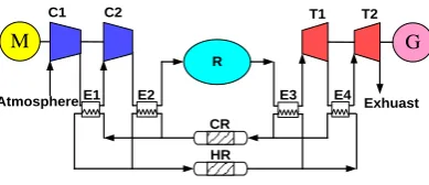
Compared with the traditional CAES, there are added heat exchanger units and storage units, which are the key parts of AA-CAES. Luo et al. built an AA-CAES model with a low-temperature thermal storage system (Figure 7), and the parameters of the whole system were optimized by simulation study [32]. From the study of Liu et al., it is shown that the exhaust temperature is still too high from the AA-CAES low pressure turbine, causing a lot of waste, and an approach was proposed for improvement of exergy efficiency of AA-CEAS systems [33].
G C1 CR T1 T2 R Exhuast M Atmosphere C2 HR
E1 E2 E3 E4
Figure 7. Schematic diagram of AA-CAES system with a low-temperature thermal storage (C— Compressor, T—Turbine, G—Generator, M—Motor, R—Reservoir, HR—Thermal storage, CR—Low-temperature thermal storage, E—Heat Exchanger) [32].
As shown in Figure 8, Barbour et al., proposed to use packed bed (PCB) heat exchangers instead of indirect heat exchangers in the AA-CAES system, and the whole cycle thermal efficiency was claimed up to be 70% with the energy stored and utilized by the cascades structure [34]. Sciacovelli et al., designed a dynamic model of the AA-CAES with PCB thermal energy storage, and then studied the transient characteristics of the thermal energy storage stages, caves, compression and expansion stages and integrated system. The results showed that the whole efficiency of the system reached 70%, when thermal efficiency of the reservoir reached 95% [35]. Tessier et al., designed a new type AA-CAES with cascades of phase change materials (PCMs), and the melting temperature and enthalpy of the PCMs were optimized for the entire system to improve efficiency and 85% efficiency is shown by the simulation results [36].
Figure 6. Schematic diagram of AA-CAES system (C—Compressor, T—Turbine, G—Generator, M—Motor, R—Reservoir, H—Thermal storage).
Yang et al., pointed out that the fewer the compression stages that are used with the same expansion pressure, the larger the system output power will be; and the more expansion stages that are used with the same compression pressure, the more the output power of the air unit mass will be, so two-stage compression and three-stage expansion are chosen for the CAES systems under a fixed total pressure ratio [29,30]. Zhao et al., designed a dynamic model of the hybrid energy storage with wind, which combined AA-CAES and a flywheel energy storage system (FESS), and the simulation results showed that the power output could meet the load demand [31].
Compared with the traditional CAES, there are added heat exchanger units and storage units, which are the key parts of AA-CAES. Luo et al. built an AA-CAES model with a low-temperature thermal storage system (Figure7), and the parameters of the whole system were optimized by simulation study [32]. From the study of Liu et al., it is shown that the exhaust temperature is still too high from the AA-CAES low pressure turbine, causing a lot of waste, and an approach was proposed for improvement of exergy efficiency of AA-CEAS systems [33].
Energies 2017, 10, 991 6 of 22
improve the efficiency of the whole cycle [27,28]. For an AA-CAES with thermal storage integration, heat released from compression stages can be stored in adiabatic containers and reused during the expansion stages. The typical working principle of AA-CAES is illustrated in Figure 6, from which it can be seen that the thermal storage is in use before the air enters the air reservoir.
G
H Atmosphere T R ExhuastM
CFigure 6. Schematic diagram of AA-CAES system (C—Compressor, T—Turbine, G—Generator, M— Motor, R—Reservoir, H—Thermal storage).
Yang et al., pointed out that the fewer the compression stages that are used with the same expansion pressure, the larger the system output power will be; and the more expansion stages that are used with the same compression pressure, the more the output power of the air unit mass will be, so two-stage compression and three-stage expansion are chosen for the CAES systems under a fixed total pressure ratio [29,30]. Zhao et al., designed a dynamic model of the hybrid energy storage with wind, which combined AA-CAES and a flywheel energy storage system (FESS), and the simulation results showed that the power output could meet the load demand [31].
Compared with the traditional CAES, there are added heat exchanger units and storage units, which are the key parts of AA-CAES. Luo et al. built an AA-CAES model with a low-temperature thermal storage system (Figure 7), and the parameters of the whole system were optimized by simulation study [32]. From the study of Liu et al., it is shown that the exhaust temperature is still too high from the AA-CAES low pressure turbine, causing a lot of waste, and an approach was proposed for improvement of exergy efficiency of AA-CEAS systems [33].
G C1 CR T1 T2 R Exhuast M Atmosphere C2 HR
E1 E2 E3 E4
Figure 7. Schematic diagram of AA-CAES system with a low-temperature thermal storage (C— Compressor, T—Turbine, G—Generator, M—Motor, R—Reservoir, HR—Thermal storage, CR—Low-temperature thermal storage, E—Heat Exchanger) [32].
[image:7.595.200.395.491.575.2]As shown in Figure 8, Barbour et al., proposed to use packed bed (PCB) heat exchangers instead of indirect heat exchangers in the AA-CAES system, and the whole cycle thermal efficiency was claimed up to be 70% with the energy stored and utilized by the cascades structure [34]. Sciacovelli et al., designed a dynamic model of the AA-CAES with PCB thermal energy storage, and then studied the transient characteristics of the thermal energy storage stages, caves, compression and expansion stages and integrated system. The results showed that the whole efficiency of the system reached 70%, when thermal efficiency of the reservoir reached 95% [35]. Tessier et al., designed a new type AA-CAES with cascades of phase change materials (PCMs), and the melting temperature and enthalpy of the PCMs were optimized for the entire system to improve efficiency and 85% efficiency is shown by the simulation results [36].
Figure 7. Schematic diagram of AA-CAES system with a low-temperature thermal storage (C—Compressor, T—Turbine, G—Generator, M—Motor, R—Reservoir, HR—Thermal storage, CR—Low-temperature thermal storage, E—Heat Exchanger) [32].
Energies2017,10, 991 7 of 22
Energies 2017, 10, 991 7 of 22
[image:8.595.188.410.86.178.2]C1 R Atmosphere
M
ExhuastG
T1 PCB1 PCB2 C2 T2Figure 8. Schematic diagram of AA-CAES system with PCB units (C—Compressor, T—Turbine, G— Generator, M—Motor, R—Reservoir) [34].
3.2. Liquid Air Energy Storage (LAES)
LAES can be considered as one type of CAES system which aims to increase the energy storage density. As shown in Figure 9, there are two stages of the cycle operation: the charging stage (the air with a certain pressure from compressors was liquefied and then stored in low-temperature storage tanks) and the discharge stage (the liquefied air becomes high pressure air with high temperature in the expanders to drive motors) [37].
C1
M
AtmosphereG
T P TANK C2 Combustor RES condenser B P LNG REFigure 9. Schematic diagram of LAES system (B—Blower, C—Compressor, T—Turbine, G— Generator, M—Motor, P—Pump, RE—Heat regenerator, RES—Waste heat generator) [37].
Liu et al., introduced a new liquid air energy storage technology [38], and the structure designs of wind/LAES systems were discussed for applications in the field of wind power. It is considered a promising way of solving the problems of the intermittence of wind power or other types of renewable energy integration in the power grid. Chino et al., modified LAES on the basis of the original gas turbine plant format. From the calculation and analysis results, it is found that the energy storage efficiency may go up to 73%, when the inlet temperature of throttling-expansion valve is higher than the temperature of liquid air at 20 K, which is of great significance for the follow-up studies [39]. Morgan et al., analyzed that the theoretical round trip efficiency is between about 40– 80%, and the round-trip efficiency is only 8% on the pilot test plant designed by Highview Power Storage. The reason for the low measured efficiency is that the air liquefier is smaller than the commercial scale air liquefier and only 51% of an available cold thermal energy was recycled [40,41]. Kantharaj et al., made full use of CAES and LAES, where LAES was used to supplement the CAES system, and highlighted the economic benefits of the hybrid system in charging and discharging time span or under limited geographical positions [42,43]. Ameel et al., studied a more complex combined cycle according to the thermodynamics of the basic cycle, and found that taking real expander efficiency reduction into account considerably reduced the actual output, unless isothermal expansion could be well approached [44].
[image:8.595.180.422.329.481.2]3.3. Supercritical Compressed Air Energy Storage (SC-CAES)
Figure 8. Schematic diagram of AA-CAES system with PCB units (C—Compressor, T—Turbine, G—Generator, M—Motor, R—Reservoir) [34].
3.2. Liquid Air Energy Storage (LAES)
LAES can be considered as one type of CAES system which aims to increase the energy storage density. As shown in Figure9, there are two stages of the cycle operation: the charging stage (the air with a certain pressure from compressors was liquefied and then stored in low-temperature storage tanks) and the discharge stage (the liquefied air becomes high pressure air with high temperature in the expanders to drive motors) [37].
Energies 2017, 10, 991 7 of 22
C1 R Atmosphere
M
ExhuastG
T1 PCB1 PCB2 C2 T2Figure 8. Schematic diagram of AA-CAES system with PCB units (C—Compressor, T—Turbine, G— Generator, M—Motor, R—Reservoir) [34].
3.2. Liquid Air Energy Storage (LAES)
LAES can be considered as one type of CAES system which aims to increase the energy storage density. As shown in Figure 9, there are two stages of the cycle operation: the charging stage (the air with a certain pressure from compressors was liquefied and then stored in low-temperature storage tanks) and the discharge stage (the liquefied air becomes high pressure air with high temperature in the expanders to drive motors) [37].
C1
M
AtmosphereG
T P TANK C2 Combustor RES condenser B P LNG REFigure 9. Schematic diagram of LAES system (B—Blower, C—Compressor, T—Turbine, G— Generator, M—Motor, P—Pump, RE—Heat regenerator, RES—Waste heat generator) [37].
Liu et al., introduced a new liquid air energy storage technology [38], and the structure designs of wind/LAES systems were discussed for applications in the field of wind power. It is considered a promising way of solving the problems of the intermittence of wind power or other types of renewable energy integration in the power grid. Chino et al., modified LAES on the basis of the original gas turbine plant format. From the calculation and analysis results, it is found that the energy storage efficiency may go up to 73%, when the inlet temperature of throttling-expansion valve is higher than the temperature of liquid air at 20 K, which is of great significance for the follow-up studies [39]. Morgan et al., analyzed that the theoretical round trip efficiency is between about 40– 80%, and the round-trip efficiency is only 8% on the pilot test plant designed by Highview Power Storage. The reason for the low measured efficiency is that the air liquefier is smaller than the commercial scale air liquefier and only 51% of an available cold thermal energy was recycled [40,41]. Kantharaj et al., made full use of CAES and LAES, where LAES was used to supplement the CAES system, and highlighted the economic benefits of the hybrid system in charging and discharging time span or under limited geographical positions [42,43]. Ameel et al., studied a more complex combined cycle according to the thermodynamics of the basic cycle, and found that taking real expander efficiency reduction into account considerably reduced the actual output, unless isothermal expansion could be well approached [44].
3.3. Supercritical Compressed Air Energy Storage (SC-CAES)
Figure 9.Schematic diagram of LAES system (B—Blower, C—Compressor, T—Turbine, G—Generator, M—Motor, P—Pump, RE—Heat regenerator, RES—Waste heat generator) [37].
Energies2017,10, 991 8 of 22
3.3. Supercritical Compressed Air Energy Storage (SC-CAES)
The SC-CAES system is a new type of CAES system which integrates the advantages of both AA-CAES and LAES: environmental protection, high energy density and high thermal efficiency. Figure10 shows a typical SC-CAES system. The air is compressed to reach to its supercritical state (p> 37.9 bar, T > 132 k); and then the supercritical compressed air is stored in tanks after a heat exchanger collects the compression heat; the liquid air becomes its gas state and generates power after being pumped to supercritical pressure and heated by the heat exchangers [37].
Energies 2017, 10, 991 8 of 22
[image:9.595.174.425.201.377.2]The SC-CAES system is a new type of CAES system which integrates the advantages of both AA-CAES and LAES: environmental protection, high energy density and high thermal efficiency. Figure 10 shows a typical SC-CAES system. The air is compressed to reach to its supercritical state (p
> 37.9 bar, T > 132 k); and then the supercritical compressed air is stored in tanks after a heat exchanger collects the compression heat; the liquid air becomes its gas state and generates power after being pumped to supercritical pressure and heated by the heat exchangers [37].
G T1
M
Waste heat
P V
Contaminant Tank CE
HE
C1 Temperature
H
Ambient
L
T2 Atmosphere
C2
Atmosphere Atmosphere
Figure 10. Schematic diagram of SC-CAES system (V—Throttle valve, C—Compressor, T—Turbine, G—Generator, M—Motor, P—Pump, HE—Heat storage & Exchanger, CE—Cold storage & Exchanger) [37].
There are two ways to perform liquefaction: throttle liquefaction valve and liquefied expander. The cooled effect of air is used by the throttle valve to obtain liquid air in the throttling process, in which the temperature is reduced. Because it is a kind of typical irreversible process, it will not only consume large amounts of energy, but also cause cavitation. The liquid expander is used to replace the throttle valve to achieve the throttling depressurization effect [37].
[image:9.595.109.488.597.746.2]In order to understand and improve the SC-CAES system, Guo et al., built a thermodynamic model. The basic simulation parameters, which are derived from practical cases in the industry, are shown in Table 4. From the study, it is found that the energy densities (3.2581–3.4602 × 10⁵ KJ/m3) could be 18 times higher than that of conventional CAES, and the round-trip efficiency could reach 67.41% [45].
Table 4. Basic simulation parameters [45].
Parameter Parameter Value
Total power output of four expanders (MW) 10
Energy releasing time (h) 1
Energy storage pressure (bar) 100
Energy releasing pressure (bar) 57.9 (V-SC-CAES)/78.5 (LE-SC-CAES)
Isentropic efficiency of compressor (%) 85
Isentropic efficiency of expander (%) 88
Isentropic efficiency of cryopump (%) 84
Isentropic efficiency of liquid expander (%) 78
Temperature difference of intercooler and reheater (K) 2
Pressure loss of each intercooler (bar) 0.2
Pressure loss of each reheater (bar) 0.2
Minimum temperature difference inside cold
storage/heat exchanger (MTDCS/HE) (K) 3
Abbreviations: V-SC-CAES, SC-CAES with throttle valve; LE-SC-CAES, SC-CAES with liquefied expander.
Figure 10.Schematic diagram of SC-CAES system (V—Throttle valve, C—Compressor, T—Turbine, G—Generator, M—Motor, P—Pump, HE—Heat storage & Exchanger, CE—Cold storage & Exchanger) [37].
There are two ways to perform liquefaction: throttle liquefaction valve and liquefied expander. The cooled effect of air is used by the throttle valve to obtain liquid air in the throttling process, in which the temperature is reduced. Because it is a kind of typical irreversible process, it will not only consume large amounts of energy, but also cause cavitation. The liquid expander is used to replace the throttle valve to achieve the throttling depressurization effect [37].
In order to understand and improve the SC-CAES system, Guo et al., built a thermodynamic model. The basic simulation parameters, which are derived from practical cases in the industry, are shown in Table4. From the study, it is found that the energy densities (3.2581–3.4602×10⁵KJ/m3) could be 18 times higher than that of conventional CAES, and the round-trip efficiency could reach 67.41% [45].
Table 4.Basic simulation parameters [45].
Parameter Parameter Value
Total power output of four expanders (MW) 10
Energy releasing time (h) 1
Energy storage pressure (bar) 100
Energy releasing pressure (bar) 57.9 (V-SC-CAES)/78.5 (LE-SC-CAES)
Isentropic efficiency of compressor (%) 85
Isentropic efficiency of expander (%) 88
Isentropic efficiency of cryopump (%) 84
Isentropic efficiency of liquid expander (%) 78
Temperature difference of intercooler and reheater (K) 2
Pressure loss of each intercooler (bar) 0.2
Pressure loss of each reheater (bar) 0.2
Minimum temperature difference inside cold
storage/heat exchanger (MTDCS/HE) (K) 3
Energies2017,10, 991 9 of 22
4. Applications of CAES
Recently, the application prospects and the potential of CAES in supporting power system operation have become widely recognized. It is predicted that CAES will play an increasingly important role in the energy management of the time of separation between generation and the usage of power. The potential applications of CAES are generally considered twofold: suppliers and consumers (behind the meter). For the power supply side, the transmission and distribution network operators can use CAES for bulk energy rescheduling for maintaining the load balance. “Behind the meter” refers to the consumer side, that is, the users can use CAES to regulate the electricity usage taken from the suppliers based on the energy price to minimize their energy bill. The potential applications of CAES are explained below.
(1) Peak Shaving and Demand Side Management
For electric power enterprises, peak shaving means the process of storing energy during off-peak periods and compensating electrical power generation shortfalls during the periods of high demand. In the different price tariff periods associated to the peak and off-peak durations, users can use CAES to manage the demand side energy by storing energy at the lower price and releasing the stored electrical energy during the periods of higher electricity price. In this way, the consumers can reduce their electricity costs. Considering the durations of long and medium term storage, Wang et al., established a demand response dynamic analysis model, which can help the owners of CAES design a target incentive mechanism that can attract the support at the project development early stage and also estimate the potential operation revenue generation [46]. Li et al., established an optimal time-of–use pricing response model, which can improve the load curve and obtain better resolution for load shifting effectively which is verified by many tests [47].
(2) Integration of More Renewable Power Generation Plants
CAES can support the seamless integration of renewable power generation plants into the existing power network to realize the goal of stable power grids, which can help solve the problems of the inherent intermittence and instability of renewable power generation [48]. In the micro-grid concept, CAES can rapidly suppress the micro-grid power fluctuations and improve power supply quality, which is important for the reliable operation of micro-grids [49,50]. Tang et al., established a simulation and experimental platform, including energy storage, photovoltaic, asynchronous wind turbines and typical load in micro-grids. The results from their study showed that effective control of energy storage could help micro-grids maintain good voltage and frequency stability during the switching process patterns of off-grid/grid pattern [51].
(3) Applications to Smart-Grids and Wind Energy Network
Smart-grids, as the future direction and trend of the electric power industry, aim to achieve energy management in both directions, that is, from both supply and consumption with the support of internet and big data technology [52,53]. Traditionally, consumers have passively accepted the electricity supplied to them so it is a direction of supply and consumption relationship; however, smart-grids will transform this structure by involving the active selection of supply, integration of local generation and dispatching energy storage sources. Rifkin, a famous American economist, believed that energy internet would be the core in the third industrial revolution, which will have a great influence on the development of society [54]. The energy internet is called smart-grid V2.0 by Li, et al., and energy storage is considered as the key enabling technologies of energy conversions and integrated applications [2].
(4) Applications to Compressed Air Engines
Energies2017,10, 991 10 of 22
a detailed review on the research and development of air-powered vehicles and pointed out that the current work should be focused on the principle and the structure optimization of air-powered automobile engines, the distribution forms and the control technology for reducing pressure [55].
(5) Applications in Other Fields
In the case of power supply system failure, CAES systems can be used as a back-up power or uninterrupted power supply (UPS), which can supply adequate power to important users, such as banks, data processing centers, hospitals and other important sectors [6,19]. CAES systems could provide the capacity of black-start in a power shutdown condition. For example, the Huntorf plant offers black-start power to the nuclear units located near the North Sea [57].
5. Current CAES Projects
[image:11.595.88.507.385.437.2]With a wide search on current reports about CAES projects, this section provides updated information in this area. A detailed comparison of the key operation parameters between the Huntorf and McIntoch CAES plants is listed in Table5[10,19,58]. These are two CAES power plants currently in commercial operation. The common feature of these two power plants is the requirement for fossil fuel (natural gas), which is not desirable for the current clean energy agenda. Low energy conversion efficiency is another key factor heavily criticized. All the current projects and researchers are attempting to avoid using fossil fuel and improve energy efficiency.
Table 5.Information data about the commercial CAES facilities [10,19,58].
Location Manufacturer Year of
Operation
Power Rating (MW)
Charge Time/Discharge
Time (h)
Air Pressure
(bars)
Heat
Sources Efficiency
Huntorf. Germany Browne Boveri 1978 290 8/2 46-66 Natural Gas 42% McIntosh. USA Dresser-Rand 1991 110 40/46 45-74 Natural Gas 54%
5.1. Demonstration Projects
Demonstration projects are one of key steps in the development of CAES plants and this subsection gives an overview of some built and on-going demonstration projects and facilities. Highview Power Storage started developing a LAES nearly 10 years ago and the company has mastered many key technologies in this particular area. The first 350 KW/2.5 MWh LAES pilot plant with packed bed cold and thermal storage has demonstrated its value by connection with the local distribution network as shown in Figure11. The demonstration plant has now been transferred to the University of Birmingham in the UK to form a living laboratory for research and education purposes. It will also be used to develop innovative designs, such as thermal storage, with the potential to overcome the undiscovered drawbacks for the next generation of LAES. From the demonstration project, the theoretical performance and detailed cycle analysis was conducted using a classical analysis method by Morgan et al. [40,41]. As predicted, it is found that the thermal storage played a core role in improving the system efficiency, the links between the component characteristics and the system performance were elucidated by Sciacovelli, et al. [59].
Energies 2017, 10, 991 10 of 22
current work should be focused on the principle and the structure optimization of air-powered automobile engines, the distribution forms and the control technology for reducing pressure [55].
(5) Applications in Other Fields
In the case of power supply system failure, CAES systems can be used as a back-up power or uninterrupted power supply (UPS), which can supply adequate power to important users, such as banks, data processing centers, hospitals and other important sectors [6,19]. CAES systems could provide the capacity of black-start in a power shutdown condition. For example, the Huntorf plant offers black-start power to the nuclear units located near the North Sea [57].
5. Current CAES Projects
[image:11.595.221.376.643.745.2]With a wide search on current reports about CAES projects, this section provides updated information in this area. A detailed comparison of the key operation parameters between the Huntorf and McIntoch CAES plants is listed in Table 5 [10,19,58]. These are two CAES power plants currently in commercial operation. The common feature of these two power plants is the requirement for fossil fuel (natural gas), which is not desirable for the current clean energy agenda. Low energy conversion efficiency is another key factor heavily criticized. All the current projects and researchers are attempting to avoid using fossil fuel and improve energy efficiency.
Table 5. Information data about the commercial CAES facilities [10,19,58].
Location Manufacturer Year of Operation
Power Rating (MW)
Charge Time/Discharge
Time (h)
Air Pressure
(bars)
Heat
Sources Efficiency
Huntorf. Germany Browne Boveri 1978 290 8/2 46-66 Natural Gas 42% McIntosh. USA Dresser-Rand 1991 110 40/46 45-74 Natural Gas 54%
5.1. Demonstration Projects
Demonstration projects are one of key steps in the development of CAES plants and this subsection gives an overview of some built and on-going demonstration projects and facilities. Highview Power Storage started developing a LAES nearly 10 years ago and the company has mastered many key technologies in this particular area. The first 350 KW/2.5 MWh LAES pilot plant with packed bed cold and thermal storage has demonstrated its value by connection with the local distribution network as shown in Figure 11. The demonstration plant has now been transferred to the University of Birmingham in the UK to form a living laboratory for research and education purposes. It will also be used to develop innovative designs, such as thermal storage, with the potential to overcome the undiscovered drawbacks for the next generation of LAES. From the demonstration project, the theoretical performance and detailed cycle analysis was conducted using a classical analysis method by Morgan et al. [40,41]. As predicted, it is found that the thermal storage played a core role in improving the system efficiency, the links between the component characteristics and the system performance were elucidated by Sciacovelli, et al. [59].
Energies2017,10, 991 11 of 22
A multi-stage regenerative 500 KW demonstration system, named TICC-500 (Figure12), was designed jointly by Tsinghua University, Institute of Physics and Chemistry, Chinese Academy of Science and China Electric Power Research Institute and is the first such kind of facility in China. The system, which could achieve a maximum system efficiency of 33.3%, passed the various load tests and its interconnection with power grid occurred in 2014. Through the study of the demonstration system, Mei et al., revealed the conversion mechanism of energy in various air forms, and designed the protection, control systems and cooperative self-control center for achieving the security and reliability of the power system [58].
Energies 2017, 10, 991 11 of 22
A multi-stage regenerative 500 KW demonstration system, named TICC-500 (Figure 12), was designed jointly by Tsinghua University, Institute of Physics and Chemistry, Chinese Academy of Science and China Electric Power Research Institute and is the first such kind of facility in China. The system, which could achieve a maximum system efficiency of 33.3%, passed the various load tests and its interconnection with power grid occurred in 2014. Through the study of the demonstration system, Mei et al., revealed the conversion mechanism of energy in various air forms, and designed the protection, control systems and cooperative self-control center for achieving the security and reliability of the power system [58].
Figure 12. TICC-500 pilot plant [58].
Figure 13 show a 1.5 MW SC-CAES demonstration project from 2013 which was designed by Macaoenergy (Bijie) Industrial Park Development Co. Ltd and Institute of Engineering Thermophysics of the Chinese Academy of Sciences. All the performance indexes have reached or exceeded the designed targets. At present, the 1.5 MW SC-CAES system has been running for more than 3000 h successfully and the system efficiency is about 55%. With the experience gained from this demonstration project, in September 2016, the first 10 MW AA-CAES project has been assembled as shown in Figure 14 and the system operation is scheduled for testing at the beginning of the 2017 [60].
Figure 13. 1.5 MW SC-CAES pilot plant in China [60].
Figure 14. 10 MW AA-CAES pilot plant in China [60]. Figure 12.TICC-500 pilot plant [58].
Figure13show a 1.5 MW SC-CAES demonstration project from 2013 which was designed by Macaoenergy (Bijie) Industrial Park Development Co. Ltd and Institute of Engineering Thermophysics of the Chinese Academy of Sciences. All the performance indexes have reached or exceeded the designed targets. At present, the 1.5 MW SC-CAES system has been running for more than 3000 h successfully and the system efficiency is about 55%. With the experience gained from this demonstration project, in September 2016, the first 10 MW AA-CAES project has been assembled as shown in Figure14and the system operation is scheduled for testing at the beginning of the 2017 [60].
Energies 2017, 10, 991 11 of 22
A multi-stage regenerative 500 KW demonstration system, named TICC-500 (Figure 12), was designed jointly by Tsinghua University, Institute of Physics and Chemistry, Chinese Academy of Science and China Electric Power Research Institute and is the first such kind of facility in China. The system, which could achieve a maximum system efficiency of 33.3%, passed the various load tests and its interconnection with power grid occurred in 2014. Through the study of the demonstration system, Mei et al., revealed the conversion mechanism of energy in various air forms, and designed the protection, control systems and cooperative self-control center for achieving the security and reliability of the power system [58].
Figure 12. TICC-500 pilot plant [58].
Figure 13 show a 1.5 MW SC-CAES demonstration project from 2013 which was designed by Macaoenergy (Bijie) Industrial Park Development Co. Ltd and Institute of Engineering Thermophysics of the Chinese Academy of Sciences. All the performance indexes have reached or exceeded the designed targets. At present, the 1.5 MW SC-CAES system has been running for more than 3000 h successfully and the system efficiency is about 55%. With the experience gained from this demonstration project, in September 2016, the first 10 MW AA-CAES project has been assembled as shown in Figure 14 and the system operation is scheduled for testing at the beginning of the 2017 [60].
Figure 13. 1.5 MW SC-CAES pilot plant in China [60].
Figure 14. 10 MW AA-CAES pilot plant in China [60]. Figure 13.1.5 MW SC-CAES pilot plant in China [60].
Energies 2017, 10, 991 11 of 22
A multi-stage regenerative 500 KW demonstration system, named TICC-500 (Figure 12), was designed jointly by Tsinghua University, Institute of Physics and Chemistry, Chinese Academy of Science and China Electric Power Research Institute and is the first such kind of facility in China. The system, which could achieve a maximum system efficiency of 33.3%, passed the various load tests and its interconnection with power grid occurred in 2014. Through the study of the demonstration system, Mei et al., revealed the conversion mechanism of energy in various air forms, and designed the protection, control systems and cooperative self-control center for achieving the security and reliability of the power system [58].
Figure 12. TICC-500 pilot plant [58].
Figure 13 show a 1.5 MW SC-CAES demonstration project from 2013 which was designed by Macaoenergy (Bijie) Industrial Park Development Co. Ltd and Institute of Engineering Thermophysics of the Chinese Academy of Sciences. All the performance indexes have reached or exceeded the designed targets. At present, the 1.5 MW SC-CAES system has been running for more than 3000 h successfully and the system efficiency is about 55%. With the experience gained from this demonstration project, in September 2016, the first 10 MW AA-CAES project has been assembled as shown in Figure 14 and the system operation is scheduled for testing at the beginning of the 2017 [60].
Figure 13. 1.5 MW SC-CAES pilot plant in China [60].
Energies2017,10, 991 12 of 22
5.2. Projects under Preparation and Construction
As described above, CAES is expected to play an important role in the future electric power system operation, so a number of projects around the world are planned or in construction. In Germany, as shown in Figure15, the world’s first large-scale AA-CAES project—ADELE—with 70% cycle efficiency has been designed by RWE Power, General Electric and other partners. The aim of this project is to optimize the co-existence and smooth interaction of the individual energy sources, especially for wind power. It is planned to have 1 GWh storage capacity and be capable of generating up to 200 MW, said the RWE power. The ADELE project could provide backup capacity within a very short time and replace forty state-of-the -art wind turbines for a period of 5 h. The project is now on hold due to uncertain business conditions [61].
Energies 2017, 10, 991 12 of 22
5.2. Projects under Preparation and Construction
[image:13.595.195.403.244.382.2]As described above, CAES is expected to play an important role in the future electric power system operation, so a number of projects around the world are planned or in construction. In Germany, as shown in Figure 15, the world’s first large-scale AA-CAES project—ADELE—with 70% cycle efficiency has been designed by RWE Power, General Electric and other partners. The aim of this project is to optimize the co-existence and smooth interaction of the individual energy sources, especially for wind power. It is planned to have 1 GWh storage capacity and be capable of generating up to 200 MW, said the RWE power. The ADELE project could provide backup capacity within a very short time and replace forty state-of-the -art wind turbines for a period of 5 h. The project is now on hold due to uncertain business conditions [61].
Figure 15. Visualization of the ADELE storage plant [61].
In America, Ridge Energy Storage has proposed a CAES system in Matagorda, Texas. The economic and technical feasibility of the wind/CAES system has been studied by Fertig and Apt, using wind power data, electricity prices hourly, and natural gas prices monthly [62]. Extensive research was conducted for profit analysis through incorporating a multiparameter vector of the integrated CAES system with wind power, such as the size, transmission capacity, and dispatch strategy and the results are very positive [62]. Park and Baldick also investigated the long-term impacts of CAES operation through a 4-week optimal operation model of the CAES with wind farms, and then a mixed integer programming (MIP) formulation for the simulation of integrating CAES in the transmission system to increase wind power production, satisfying 20% renewable portfolio standard target [63]. Liu et al., found CAES systems financially attractive in its development for integrating a large share of wind power after the use of nodal pricing [64]. However, the project stopped as it is found that the underground geological condition does not satisfy the requirement of compressed air storage, although big spending has incurred. This provides an example for the importance of geological survey for a suitability study of underground storage.
In China, there is a 100 MW SC-CAES project planned to be in operation before 2020, which is designed by Institute of Engineering Thermophysics, Chinese Academy of Sciences and its partners [63]. There is another 50 MW AA-CAES project underway in Jiansu, China, in 2017, which is certified by the consulting panel. In this 50 MW AA-CAES system, underground salt caverns are adopted as the air reservoirs [65]. The final objective is to build 100 MW AA-CAES informed by the learnings from the 50 MW system.
In 2015, Hydrostor has planned a pilot project for the World’s First Offshore Compressed-Air Energy Storage Project in Toronto (Canada) [66]. It would be the first test of an underwater compressed-air energy storage system. The project uses drilling techniques that reduce the demand for boats and cranes at the surface to deploy the pipes and storage balloons.
On land, electricity runs a compressor to produce the compressed air. During that process, waste heat is captured and could be used to increase the round-trip efficiency from about 60 percent to as high as 80 percent. The compressed air is pressurized to match the pressure at the ocean floor where
Figure 15.Visualization of the ADELE storage plant [61].
In America, Ridge Energy Storage has proposed a CAES system in Matagorda, Texas. The economic and technical feasibility of the wind/CAES system has been studied by Fertig and Apt, using wind power data, electricity prices hourly, and natural gas prices monthly [62]. Extensive research was conducted for profit analysis through incorporating a multiparameter vector of the integrated CAES system with wind power, such as the size, transmission capacity, and dispatch strategy and the results are very positive [62]. Park and Baldick also investigated the long-term impacts of CAES operation through a 4-week optimal operation model of the CAES with wind farms, and then a mixed integer programming (MIP) formulation for the simulation of integrating CAES in the transmission system to increase wind power production, satisfying 20% renewable portfolio standard target [63]. Liu et al., found CAES systems financially attractive in its development for integrating a large share of wind power after the use of nodal pricing [64]. However, the project stopped as it is found that the underground geological condition does not satisfy the requirement of compressed air storage, although big spending has incurred. This provides an example for the importance of geological survey for a suitability study of underground storage.
In China, there is a 100 MW SC-CAES project planned to be in operation before 2020, which is designed by Institute of Engineering Thermophysics, Chinese Academy of Sciences and its partners [63]. There is another 50 MW AA-CAES project underway in Jiansu, China, in 2017, which is certified by the consulting panel. In this 50 MW AA-CAES system, underground salt caverns are adopted as the air reservoirs [65]. The final objective is to build 100 MW AA-CAES informed by the learnings from the 50 MW system.
In 2015, Hydrostor has planned a pilot project for the World’s First Offshore Compressed-Air Energy Storage Project in Toronto (Canada) [66]. It would be the first test of an underwater compressed-air energy storage system. The project uses drilling techniques that reduce the demand for boats and cranes at the surface to deploy the pipes and storage balloons.
![Figure 1.Figure 1. Capital energy cost vs. capital power cost [6–10]. Capital energy cost vs](https://thumb-us.123doks.com/thumbv2/123dok_us/9448393.452023/3.595.82.516.257.406/figure-figure-capital-energy-capital-power-capital-energy.webp)


![Table 2. Various storage media and plant configurations of air storage reservoir [9].](https://thumb-us.123doks.com/thumbv2/123dok_us/9448393.452023/6.595.79.517.586.664/table-various-storage-media-plant-congurations-storage-reservoir.webp)
![Figure 9. Figure 9. Schematic diagram of LAES system (B—Blower, C—Compressor, T—Turbine, G—Generator, M—Motor, P—Pump, RE—Heat regenerator, RES—Waste heat generator) [37]](https://thumb-us.123doks.com/thumbv2/123dok_us/9448393.452023/8.595.188.410.86.178/figure-figure-schematic-compressor-turbine-generator-regenerator-generator.webp)
![Table 4. Basic simulation parameters [45].](https://thumb-us.123doks.com/thumbv2/123dok_us/9448393.452023/9.595.109.488.597.746/table-basic-simulation-parameters.webp)
![Table 5. Information data about the commercial CAES facilities [10,19,58].Table 5. Information data about the commercial CAES facilities [10,19,58]](https://thumb-us.123doks.com/thumbv2/123dok_us/9448393.452023/11.595.221.376.643.745/table-information-commercial-facilities-table-information-commercial-facilities.webp)
![Figure 15.Figure 15. Visualization of the ADELE storage plant [ Visualization of the ADELE storage plant [61]](https://thumb-us.123doks.com/thumbv2/123dok_us/9448393.452023/13.595.195.403.244.382/figure-figure-visualization-adele-storage-visualization-adele-storage.webp)
![Figure 16.Figure 16. Schematic of CAES system for offshore wind energy storage and generation [ Schematic of CAES system for offshore wind energy storage and generation [70]](https://thumb-us.123doks.com/thumbv2/123dok_us/9448393.452023/15.595.191.404.88.264/figure-schematic-offshore-generation-schematic-offshore-storage-generation.webp)
