ISSN: 2089-3272, DOI: 10.11591/ijeei.v6i1.338 79
Android Application for Microcontroller-based Reservoir
Water Level Monitoring
Cyril Dale L. Cero1, Konzeff Joy L. Ala2, Edwin R. Arboleda*3
Department of Computer and Electronics Engineering, College of Engineering and Information Technology, Cavite State University, Indang, Cavite, Philippines
Article Info ABSTRACT
Article history: Received Jan 4, 2018 Revised Jan 20, 2018 Accepted Feb 3, 2018
A reservoir water level monitoring system was designed, constructed using a microcontroller and evaluated through functionality, reliability and accuracy. The monitoring system components consisted of a Gizduino microcontroller, Ethernet shield, serial camera and float switches which enabled the system to provide real time status and pictures of the reservoir. The monitoring system can be accessed using an Android application that can be installed in a compatible Android smartphone. An internet connection with a dedicated public IP was needed to broadcast the status and pictures of the reservoir. The specific monitoring system is fixed to a specific dam as it has a set of different float switches and camera. A back-up battery supply was integrated to the monitoring system to provide continuous power to the system. Fifty students evaluated the user acceptance of the water level monitoring system. According to the participants, the system was user-friendly, functional, reliable and accurate.
Keyword: Android Integration Microcontroller Reservoir
Water level monitoring system
Copyright © 2018 Institute of Advanced Engineering and Science. All rights reserved. Corresponding Author:
Edwin R. Arboleda,
Department of Computer and Electronics Engineering, College of Engineering and Information Technology, Cavite State University,
Indang, Cavite, Philippines.
Email: [email protected]
1. INTRODUCTION
A reservoir is a natural or artificial storage of water. This can be created by construction of a dam or excavation in the ground or by conventional construction techniques such as brickwork or cast concrete. It is primarily used to save, manage, and/or prevent the flow of excess water into specific regions. In addition, dams are used to generate hydropower. It can also be the source of water in the community [1–3].
Reservoir water level is monitored in order to prevent spillage and dam breaks. It is necessary to assess the need of opening the spillway gates to prevent an overflow of water from the dam. Having a monitoring program, especially when real time data are monitored, these problems can be detected early and alarm the citizens on the current situation of the dam [4,5].
Measuring water level in a flood alert system includes submersible pressure sensor, bubbler system, shaft encoder, and the latest technology, a non-contact radar level system [6,7]. In most flood alert systems, rainfall is an early warning trigger to flood events. To measure rainfall, a tipping bucket rain gauge is most typically used. The tipping bucket rain gauge features SDI-12 output to make integration and troubleshooting the system rather simple [8]. A side-looking or up-looking current meter may be required to calculate water flow for monitoring sites that are not gravity fed or may have variable backwater. At these sites, measuring water level is not sufficient for determining discharge [9–11]. Data indicating a water velocity change while water level remains fixed can be an important trigger for flood events
Transmitting and alarming is perhaps one of the most important components of a flood warning system. There are three primary options available in the complete flood monitoring kit including: data to the web, ALERTS network transmissions, and point to point data to the desktop [6,12].
Real time monitoring system is essential in our daily lives. It shows accurate and current updates of what is happening in one place or another. Many fields have been using this system for improving their services [13,14]. Beneficiary includes the system provider as well as the community. The Department of Science and Technology (DOST) and the Metro Manila Development Authority (MMDA) developed a Water Level Monitoring System (WLMS) that uses ultrasonic sensor device to measure the flood waters in real time. The information collected is transmitted via SMS to the central server [15,16].
Android application that is integrated with an Arduino-based rainfall monitoring system has the advantage of recording near real time data compared with the 1-minute interval data gathering of the tipping bucket [17–19]. The use of android application for the monitoring system of the South-West Integrated Provincial Transport Terminal showed that the use of android application is functional, reliable, consistent, accurate, and efficient. Integrating the android application to an Arduino-based water level monitoring system can provide real time updates that can be helpful to the management of the reservoir [20,21].
The reservoir water level monitoring system needs a public IP address in order to be viewed publicly. The Ethernet shield will handle the web server capabilities and will not rely on remote server capabilities [5,22,23]. The role of the DNS name servers maintained by the hosting company is to respond to a query for a specific domain name with the precise location on the exact web hosting server (using that server’s IP address) where that domain name, and thus web site, is located [24–26]. One monitoring system is required per dam as it has a set of different float switches and a camera per reservoir.
The study aimed to develop an Android-based reservoir water level monitoring system, design and construct the circuitry of the reservoir water level monitoring system, develop an Android application that will broadcast the current status of dam via photo and data, test and evaluate the performance of the system and determine the cost of the system.
2. RESEARCH METHOD
The water level monitoring system was enhanced by using an Android application accessed with the use of internet connection. This provided a remote communication with the system. The methods used in creating the monitoring system were combined with a microcontroller-based system connected to the camera and float sensors.
2.1. Design of the Water Level Monitoring System
The water level monitoring system is an Android-based, microcontroller-based system hat is able to connect to the internet for uploading real time picture and data taken from the camera and float switches. The system used a microcontroller to handle the camera and web server capabilities with the use of a low powered controller. This was used to provide a simple and reliable system for the reservoir water level monitoring system.
The end user will use an Android based application o utilize the reservoir monitoring system. Android was chosen as the software platform due to its availability and ease of development through the use of Android studio.
The water level monitoring system was designed to be deployed in the different reservoirs. The monitoring system requires an internet service within its facility to provide connection for the monitoring system. The monitoring system is not applicable to all the dams due to need of an internet connection and a public IP address to utilize the monitoring system. A DNS hosting can be used to provide a public IP for the monitoring system. However, for evaluation purposes, remote simulation was done to recreate the actual happenings in the reservoir with the use of CvSU’s public IP address.
2.2. Principle of Operation
The water level monitoring system is connected to the internet port of the CvSU to provide internet connectivity to the system as well as providing the system its public IP address. The system is turned on and the microcontroller initialized and set up the IP address, MAC address, gateway, DNS and subnet of the system. The system will then check the reservoir’s water level status by checking the float switches condition and simultaneously logging the time and status of the reservoir to the SD card of the monitoring system. Then the system will then take a picture of the reservoir and save the picture taken to the SD card of the system. The system will then be available to any clients requesting for the update of the reservoir system when the user refreshes the Android application. The sampling time of the water level monitoring system
depends on the water level of the reservoir. This was made to conserve the energy consumption of the system.
The system is powered through the main AC line and has a back-up power supply using a lead acid battery that automatically supplies the system in case of power interruption or power failure.
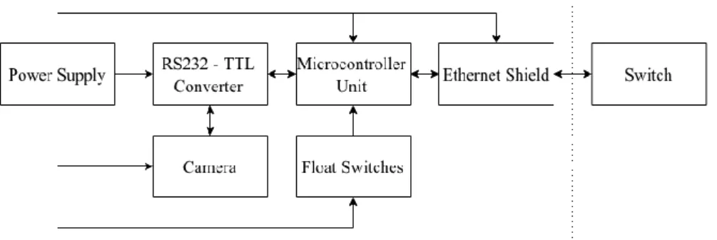
Figure 1. Water level monitoring system block diagram
2.3. Testing and Evaluation
In the technical evaluation, the system’s reliability and responsiveness were evaluated by the researchers. The system’s reliability was tested through stress test and continuous operation of the system for the whole 24 h. The system must be accessible and available throughout the entire reliability test. The system’s responsiveness was tested through changing the water level of the reservoir and timing the response of the system to the water level changes. The system’s responsiveness was tested 30 times per water level condition. In the user evaluation, the user interaction, functionality, reliability and accuracy were evaluated by the 50 student participants. The results of the evaluation were analyzed using statistical parameters such as mean, frequency distribution and T-test.
3. RESULTS AND ANALYSIS
This section presents the results of analysis and interpretation of data gathered with the end view of answering the problem of this research work. Presentation of device and network layout was also included. 3.1. System Description
The reservoir monitoring system is composed of three major hardware parts, namely: the power supply, system unit and the internet system.
The power supply was made to provide power to the system and provide back-up power in case of power interruption or power failure (Figure 2). The main system unit was made up of Gizduino 4.1 microcontroller, Ethernet shield, real time clock, RS232-TTL converter, serial camera and float switches. The microcontroller is the one that process the data to be done. The Ethernet shield [23] provides internet connectivity to the monitoring system. The real time clock handles the time of the system (Figure 3). The serial camera handles the taking of pictures of the reservoir with the help of RS232-TTL converter [24] in order for the microcontroller to process the data from the serial camera (Figure 4). contained within a fixed housing [25], it triggers the different conditions that changes the reservoir status (Figure 5). The float switches comprise a magnet contained within a float, as well as a magnetic reed switch
The software part of the system is the Android application. The Android application has three major parts, namely: splash screen, start screen, and the main activity page.
When the Android application is opened, the splash screen will appear and the picture of the application will be flashed (Figure 6) and it has a Start button that is clickable that activates the next page which is the main activity page (Figure 7).
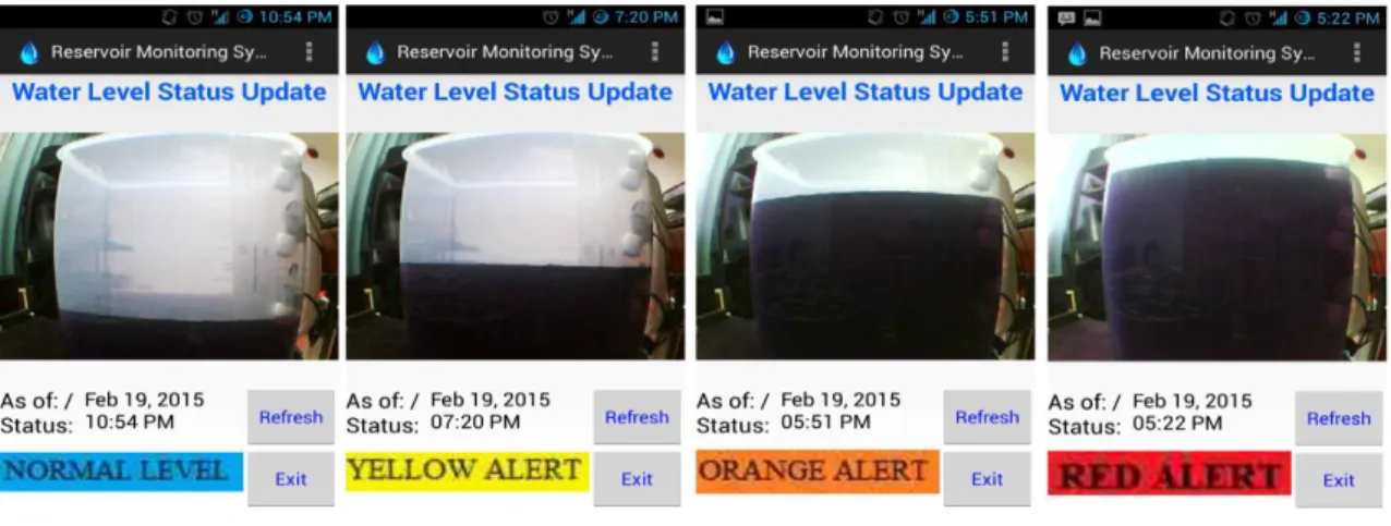
The main page displays the latest picture and status of the reservoir. It has two buttons: refresh and exit buttons. The refresh button will fetch the latest picture and status of the reservoir while the exit button triggers the application to go back to the start page. It will show different levels and alerts depending on the status of the reservoir (Figure 8). The application automatically refreshes every 2 min and loads the recent picture and status of the reservoir.
Figure 8. The main activity page depending on the reservoir status
3.2. Reliability of the Water Level Monitoring System
The reservoir monitoring system passed the 24-hour evaluation. The monitoring system broadcasted the reservoir picture and status. The fully-charged system’s backup battery lasted for 10 h and 14 min. The system’s backup battery was charged using the same power supply and fully charged for 6 h with 12.60 V. The whole system consumes 530 mA from the battery. The system unit consumed 170 mA. The biggest power consumer from the battery was the fan which consumed 360 mA from the battery.
3.3. Responsiveness of the Water Level Monitoring System
The test done by the researchers testing the responsiveness of the water level monitoring system through triggering the change of water level of the reservoir showed that the shortest response time of the monitoring system was 25.24 s and the longest response time of the system was 34.93 s (Table 1).
Table 1. Response time from one level to another
ITEM MEAN RATING
User acceptance 4.52
Functionality 4.42
Reliability 4.41
Accuracy 4.47
Overall Average 4.46
3.4. Acceptability of the Water Level Monitoring System
The acceptability was evaluated by the researchers with the use of questionnaires that was answered by the students from different courses. The four major parts namely user interaction, functionality, reliability and accuracy, respectively. The participants found that the reservoir monitoring system was user-friendly, functional, reliable and accurate (Table 2).
Table 2. User evaluation results RESERVOIR WATER LEVEL
STATUS N MINIMUM MAXIMUM MEAN
STD. DEVIATION Normal to Yellow 30 25.24 34.58 28.12 2.18 Yellow to Normal 30 25.88 32.88 29.59 1.63 Yellow to Orange 30 27.39 32.32 29.83 1.36 Orange to Yellow 30 27.93 34.93 29.70 1.37 Orange to Red 30 27.75 32.84 30.56 1.23 Red to Orange 30 28.61 32.62 30.21 1.16
3.5. Cost Computation
The reservoir water level monitoring system cost P 7,145. The system unit cost P 4,981 and the power supply component amounted to P 2,164.
4. CONCLUSION
Based on the results of the study, the reservoir water level monitoring system with Android application can monitor and remotely view the real-time status of the dam using internet. The system successfully collaborated with the developed Android application. It was able to broadcast the current image of the simulated dam and its corresponding alert level. Based on the evaluation results, the monitoring system was found to be user-friendly, functional, reliable and accurate.
REFERENCES
[1] Ahmad S, Simonovic SP. System Dynamics Modeling of Reservoir Operations for Flood Management. J Comput Civ Eng [Internet]. 2000;14(3):190–8. Available from: http://ascelibrary.org/doi/10.1061/%28ASCE%290887-3801%282000%2914%3A3%28190%29
[2] Ahmed T, McKinney PD. Advanced Reservoir Engineering. Advanced Reservoir Engineering. 2005. [3] Ahmed T. Reservoir Engineering Handbook. Chemical, Petrochemical & Process. 2006. 811-817 p.
[4] Jiang P, Xia H, He Z, Wang Z. Design of a water environment monitoring system based on wireless sensor networks. Sensors. 2009;9(8):6411–34.
[5] Shivaray S., Shrinath P., Sharath. S, Balapradeep K. Water Level Monitoring and Flood Alert System. Int J Res [Internet]. 2014;1(5):487–91. Available from: http://internationaljournalofresearch.org/index.php/ijr/article/view/185 [6] Hussin SAS, Ismail MN, Sofian H. Intelligent flood information system via SMS (IFIS). Proc 6th Int Conf Ubiquitous Inf Manag Commun - ICUIMC ’12 [Internet]. 2012;(FEBRUARY 2012):1. Available from: http://dl.acm.org/citation.cfm?doid=2184751.2184830
[7] Fierro R, Castillo O, Valdez F, Melin P. Optimization of Membership Functions for the Fuzzy Controllers of the Water Tank and Inverted Pendulum with Differents PSO Variants. TELKOMNIKA (Telecommunication Comput Electron Control. 2013;11(4):699–714.
[8] Thomsen A, Hansen B, Schelde K. Application of TDR to water level measurement. J Hydrol. 2000;236(3–4):252– 8.
[9] Li X, Guo S, Liu P, Chen G. Dynamic control of flood limited water level for reservoir operation by considering inflow uncertainty. J Hydrol. 2010;391(1–2):124–32.
[10]Kotta HZ, Rantelobo K, Tena S, Klau G. Wireless Sensor Network for Landslide Monitoring in Nusa Tenggara Timur. TELKOMNIKA (Telecommunication, Comput Electron Control [Internet]. 2011;9(1):9–18. Available from: http://telkomnika.ee.uad.ac.id/n9/files/Vol.9No.1Apr11/9.1.04.11.02.pdf
[11]Carsell KM, Pingel ND, Ford DT. Quantifying the Benefit of a Flood Warning System. Nat Hazards Rev. 2004;5(3):131–40.
[12]Schmid U. Monitoring distributed real-time systems. Real-Time Syst. 1994;7(1):33–56.
[13]Engineering A, Vidya B, Poonam K, Priyanka G, Gaurav D, Chandgude PAS. Water Level Monitoring System In Real Time Mode Using WSN. Int J Emerg Technol Adv Eng. 2016;6(9):212–4.
[14]Dake LP. Fundamentals of Reservoir Engineering [Internet]. Vol. 42, Environmental science technology. 2008. p.
2742–7. Available from:
http://www.pubmedcentral.nih.gov/articlerender.fcgi?artid=2929141&tool=pmcentrez&rendertype=abstract [15]Chang DTT, Tsai Y-S, Yang K-C. Study of Real-Time Slope Stability Monitoring System Using Wireless Sensor
Network(WSN). TELKOMNIKA Indones J Electr Eng. 2013;11(3):1478–88.
[16]Barrett EC, Beaumont MJ. Satellite rainfall monitoring: an overview. Remote Sens Rev [Internet]. 1994;11(1– 4):23–48. Available from: http://www.scopus.com/inward/record.url?eid=2-s2.0-0028682507&partnerID=tZOtx3y1 [17]Piyare R. Internet of Things : Ubiquitous Home Control and Monitoring System using Android based Smart Phone.
Int J Internet Things. 2013;2(1):5–11.
[18]Gertz E, Justo P Di. Environmental Monitoring with Arduino. O’Reilly Media. 2012. 80 p.
[19]Chao BF, Wu YH, Li YS. Impact of Artificial Reservoir Water Impoundment on Global Sea Level. Science (80- ) [Internet]. 2008;320(5873):212–4. Available from: http://www.sciencemag.org/cgi/doi/10.1126/science.1154580 [20]Chang F-J, Chang Y-T. Adaptive neuro-fuzzy inference system for prediction of water level in reservoir. Adv Water
Resour. 2006;29(1):1–10.
[21]Sun E, Wang C, Tian F. A Survey on Multipath Routing Protocols in Wireless Multimedia Sensor Networks.
TELKOMNIKA Indones J Electr Eng [Internet]. 2014;12(9):6978–83. Available from:
http://iaesjournal.com/online/index.php/TELKOMNIKA/article/view/4767
[22]Lee S, Jeong JP, Park JS. DNSNA: DNS name autoconfiguration for Internet of Things devices. In: International Conference on Advanced Communication Technology, ICACT. 2016. p. 410–6.
[23]Brownlee N, Claffy KC, Nemeth E. DNS measurements at a root server. GLOBECOM’01 IEEE Glob Telecommun Conf (Cat No01CH37270) [Internet]. 2001;3(1):1672–6. Available from: http://ieeexplore.ieee.org/lpdocs/epic03/wrapper.htm?arnumber=965864
[24]Baharum MS, Awang RA, Baba NH. Flood monitoring system (MyFMS). In: Proceedings - 2011 IEEE International Conference on System Engineering and Technology, ICSET 2011. 2011. p. 204–8.
[25]Bergasa LM, Nuevo J. Real-time system for monitoring driver vigilance. In: IEEE International Symposium on Industrial Electronics. 2005. p. 1303–8.
[26]Trono EM, Guico ML, Libatique NJ., Tangonan GL, Baluyot DNB, Cordero TKR, et al. Rainfall monitoring using acoustic sensors. TENCON 2012 IEEE Reg 10 Conf [Internet]. 2012;1–6. Available from: http://ieeexplore.ieee.org/lpdocs/epic03/wrapper.htm?arnumber=6412284