Channel Modelling For 5G and
Beyond
by
Yi Tan
Submitted for the degree of Doctor of Philosophy
at
Heriot-Watt University
School of Engineering and Physical Sciences
December 2019
The copyright in this thesis is owned by the author. Any quotation from the thesis or use of any of the information contained in it must acknowledge this thesis as the source of the quotation or information.
Millimetre wave (mmWave) wireless communication is one of the most promising technologies for the fifth generation (5G) wireless communication networks and be-yond. The very broad bandwidth and directional propagation are the two features of mmWave channels. In order to develop the channel models properly reflecting the characteristics of mmWave channels, the in-depth studies of mmWave channels ad-dressing those two features are required. In this thesis, three mmWave channel models and one beam alignment scheme are proposed related to those two features.
First, for studying the very broad bandwidth feature of mmWave channels, we in-troduce an averaged power delay profile (APDP) method to estimate the frequency stationarity regions (FSRs) of channels. The frequency non-stationary (FnS) proper-ties of channels are found in the data analysis. A FnS model is proposed to model the FnS channels in both the sub-6 GHz and mmWave frequency bands and cluster evolution in the frequency domain is utilised in the implementation of FnS model. Second, for studying the directional propagation feature of mmWave channels, we develop an angular APDP (A-APDP) method to study the planar angular stationar-ity regions (ASRs) of directional channels (DCs). Three typical directional channel impulse responses (D-CIRs) are found in the data analysis and light-of-sight (LOS), non-LOS (NLOS), and outage classes are used to classify those DCs. A modified Saleh-Valenzuela (SV) model is proposed to model the DCs. The angular domain cluster evolution is utilised to ensure the consistency of DCs.
Third, we further extend the A-APDP method to study the spherical-ASRs of DCs. We model the directional mmWave channels by three-state Markov chain that consists of LOS, NLOS, and outage states and we use stationary model, non-stationary model, and “null” to describe the channels in each Markov state according to the estimated ASRs. Then, we propose to use joint channel models to simulate the instantaneous directional mmWave channels based on the limiting distribution of Markov chain. Finally, the directional propagated mmWave channels when the Tx and Rx in motion is addressed. A double Gaussian beams (DGBs) scheme for mobile-to-mobile (M2M) mmWave communications is proposed. The connection ratios of directional mmWave channels in each Markov state are studied.
My greatest appreciation goes to my primary supervisor Prof. Cheng-Xiang Wang for giving me the golden opportunity to do research. I would like to gratefully acknowl-edge his invaluable and patient guidance in all the researches toward my doctoral study and writing this thesis. Without his precious support, it would not be possible to accomplish this work. My sincere thanks must go to my secondary supervisors Prof. George Goussetis for his advice and his generosity to give me access to the research facilities in his laboratory. I am also very grateful to visiting researcher Prof. Qiuming Zhu from Nanjing University of Aeronautics and Astronautics for the discussions and cooperation of original papers.
I would like to express my heartfelt gratitude to my colleagues Carlos Lopez, Yu Fu, Ahmed Al-Kinani, Qianru Zhou, Liang Gong, and the visiting researchers from China Zhou Li, Prof. Minzheng Li, Yu Liu, Weijun Xing, Yuhan Ruan, Rui Zhang, Liyang Zhang, Rui Feng, Lu Bai, and Ji Bian in the Advanced Wireless Technologies (AWiTec) Lab. It was my pleasure to work with you and made progress together. Your friendship and kindness also made my stay in Edinburgh an enjoyable experience. I also would like to thank EU H2020 Marie Sk lodowska-Curie ITN project Innovative Architectures, Wireless Technologies and Tools for High Capacity and Sustainable 5G Ultra-Dense Cellular Networks (5Gwireless, No. 641985) for the financial support and well-organized training activities of international communication and cooperation. My special thanks go to Beatriz Bedia and Ana Ruiz for their kindly help during my four months secondment in TTI, Santander, Spain.
Last but not least, my great gratefulness to my wife Jingxuan Zhu and my daughter Olivia Weizhen Tan for their company and constant support. I also give my best wishes to my mother Bin He, my father Laixiao Tan, my sister Yan Huang, brother-in-law Ji Liu, other family members, and my British friends Vince Gray and Angela Gray. Thank you for all of their understanding and unconditional assistance.
Yi Tan
Page 1 of 2 RDC Clerk/Apr 2019 Please note this form should be bound into the submitted thesis.
Name: Yi Tan
School: School of Engineering & Physical Sciences
Version: (i.e. First,
Resubmission, Final) Final Degree Sought: Ph.D. degree
Declaration
In accordance with the appropriate regulations I hereby submit my thesis and I declare that: 1. The thesis embodies the results of my own work and has been composed by myself 2. Where appropriate, I have made acknowledgement of the work of others
3. The thesis is the correct version for submission and is the same version as any electronic versions submitted*. 4. My thesis for the award referred to, deposited in the Heriot-Watt University Library, should be made available for
loan or photocopying and be available via the Institutional Repository, subject to such conditions as the Librarian may require
5. I understand that as a student of the University I am required to abide by the Regulations of the University and to conform to its discipline.
6. I confirm that the thesis has been verified against plagiarism via an approved plagiarism detection application e.g. Turnitin.
ONLY for submissions including published works
Please note you are only required to complete the Inclusion of Published Works Form (page 2) if your thesis contains published works)
7. Where the thesis contains published outputs under Regulation 6 (9.1.2) or Regulation 43 (9) these are accompanied by a critical review which accurately describes my contribution to the research and, for multi-author outputs, a signed declaration indicating the contribution of each author (complete)
8. Inclusion of published outputs under Regulation 6 (9.1.2) or Regulation 43 (9) shall not constitute plagiarism. * Please note that it is the responsibility of the candidate to ensure that the correct version of the thesis is submitted.
Signature of Candidate:
Date: 18 Dec. 2019
Submission
Submitted By (name in capitals):
YI TAN Signature of Individual Submitting:
Date Submitted: 18 Dec. 2019
For Completion in the Student Service Centre (SSC)
Limited Access Requested Yes No Approved Yes No
E-thesis Submitted (mandatory for final theses)
Page 2 of 2 RDC Clerk/Apr 2019 Please note you are only required to complete the Inclusion of Published Works Form if your thesis contains published works under Regulation 6 (9.1.2)
Declaration
This thesis contains one or more multi-author published works. In accordance with Regulation 6 (9.1.2) I hereby declare that the contributions of each author to these publications is as follows:
Citation details Y. Tan, C.-X. Wang, Q. Zhu, Z. Zhang, Z. Wang, J. Huang, and R. Feng, “A
novel beamforming scheme for mobile-to-mobile millimeter wave communications,” in Proc. WSA’18, Bochum, Germany, Mar. 2018.
Author 1 Data analysis, proposing the channel model, and simulations.
Author 2 Supervising all the research related works.
Signature:
Date: 18 Dec. 2019
Citation details Y. Tan, J. Huang, R. Feng, and C.-X, Wang, “A study of angular stationarity
of 5G millimeter wave channels," in Proc. ISWCS'18 Workshop, Bologna, Italy, Aug. 2017.
Author 1 Data analysis, proposing the channel model, and simulations.
Author 2 Provide channel measurement data. Give suggestions to improve the
manuscript. Signature:
Date: 18 Dec. 2019
Citation details Y. Tan, C.-X. Wang, J. . Nielsen, and G. F. Pedersen, “Comparison of
stationarity regions for wireless channels from 2GHz to 30 GHz," in Proc. IWCMC'17, Invited Paper, Valencia, Spain, Jun. 2017.
Author 1 Data analysis, proposing the channel model, and simulations.
Author 2 Supervising all the research related works.
Signature:
Date: 18 Dec. 2019
I, Yi Tan, declare that this thesis titled, ’Statistical Millimetre Wave Channel Mod-elling For 5G And Beyond’ and the work presented in it is my own. I confirm that this work submitted for assessment is my own and is expressed in my own words. Any uses made within it of the works of other authors in any form (e.g., ideas, equations, figures, text, tables, codes) are properly acknowledged at any point of their use. A list of the references employed is included.
This work was done wholly or mainly while in candidature for a research degree
at this University.
Where any part of this thesis has previously been submitted for a degree or
any other qualification at this University or any other institution, this has been clearly stated.
Where I have consulted the published work of others, this is always clearly
attributed.
Where I have quoted from the work of others, the source is always given. With
the exception of such quotations, this thesis is entirely my own work.
I have acknowledged all main sources of help.
Where the thesis is based on work done by myself jointly with others, I have
made clear exactly what was done by others and what I have contributed myself.
Signed:
Abstract i Acknowledgement iv Declaration of Authorship v List of Figures xi List of Tables xv Abbreviations xvi Symbols xix 1 Introduction 1 1.1 Background . . . 1
1.1.1 The 5G Wireless Communication Systems and Beyond . . . 1
1.1.2 The Brief of MmWave Communication . . . 3
1.2 Motivation . . . 6
1.3 Contributions . . . 7
1.4 Original Publications . . . 9
1.5 Thesis Organisation . . . 10
2 Millimetre Wave Channel Modelling: Literature Review 13 2.1 Introduction . . . 13
2.2 The Categories of Channel Models . . . 14
2.2.1 Deterministic Channel Model . . . 15
2.2.2 Stochastic Channel Models . . . 15
2.2.3 Hybrid Channel Models . . . 18
2.3 Modelling of MmWave Channels . . . 18
2.3.1.3 MmMagic . . . 21
2.3.1.4 3GPP models, above 6 GHz . . . 22
2.3.2 Specific Characteristics of MmWave Channels . . . 23
2.3.2.1 Frequency Dependent Characteristics . . . 23
2.3.2.2 Path loss and Oxygen Absorption . . . 24
2.3.2.3 Penetration Loss and Blockage . . . 25
2.3.3 Directionality of MmWave Channels . . . 25
2.3.3.1 NYU Wireless Models . . . 26
2.3.4 Studies of Vehicular/Mobile MmWave Channels . . . 27
2.4 MmWave Channel Measurements . . . 28
2.4.1 Principle of Wide-Band Channel Sounding . . . 28
2.4.2 MmWave Channel Sounder . . . 29
2.4.3 A Short Brief of MmWave Channel Measurement Campaigns . . 31
2.5 Research Gap . . . 31
2.6 Summary . . . 35
3 Frequency non-Stationarity and Frequency non-Stationary Channel Modelling 36 3.1 Introduction . . . 36
3.1.1 Contributions . . . 39
3.2 Stationarity Regions in Time, Frequency, and Spatial Domains . . . 40
3.2.1 APDP Method Applied in Time Domain . . . 41
3.2.2 APDP Method Applied in Spatial Domain . . . 42
3.2.3 APDP Method Applied in Frequency Domain . . . 42
3.2.3.1 Case 1: Averaging on Snapshots . . . 43
3.2.3.2 Case 2: Averaging on Antenna Array . . . 45
3.3 Channel Measurements and Data Analysis . . . 46
3.3.1 Channel Measurements and Data Processing . . . 46
3.3.2 FSR Analysis . . . 48
3.3.3 Variation of Statistical Properties of Channels . . . 51
3.3.3.1 Statistical Property of Channel in Frequency Domain . 54 3.3.3.2 Variation of FCFs of Sub-Band Channels. . . 54
3.4 A FnS Channel model . . . 54
3.4.1 FnS Channel Modelling . . . 55
3.4.2 Cluster Evolution in Frequency Domain . . . 56
3.4.3 Statistical Parameters of Measured Sub-Band Channels . . . 58
3.4.3.1 Parameters Estimation . . . 58
3.4.3.2 Trends of Statistical Parameters. . . 59
3.5 Generation of FnS Channel Coefficient . . . 60
3.5.1 Generation of One Sub-Band Channel Coefficient . . . 60
3.5.2 Cluster Evolution . . . 62
3.6.1 Simulation of FnS Channels . . . 65
3.6.2 Fading of Simulated FnS channels . . . 67
3.7 Summary . . . 69
4 Planar Angular Stationarity and Directional MmWave Channel Mod-elling 71 4.1 Introduction . . . 71
4.1.1 Contributions . . . 74
4.2 Channel Measurements and Data Analysis . . . 75
4.2.1 Angular Stationarity . . . 75
4.2.2 MmWave Channel Measurements . . . 77
4.2.3 Three Typical D-CIRs in the LOS Case . . . 78
4.2.4 Two Typical D-CIRs in the NLOS Case . . . 84
4.2.5 Study of Spatial Stationarity Based on Directional MmWave Channels. . . 84
4.3 A New Modelling of Directional MmWave Channels . . . 85
4.3.1 Three Classes of DCs . . . 85
4.3.2 Inhomogeneity of MmWave Channel Environment . . . 87
4.3.3 Directional MmWave Channel Model . . . 88
4.3.4 Cluster Evolution in The Angular Domain . . . 90
4.3.5 No Cluster Drifts in Different DCs . . . 92
4.3.6 Estimation of Statistical Parameters . . . 93
4.4 Generation of Channel Coefficients . . . 97
4.4.1 Generation of First DC’s Channel Coefficient/D-CIR . . . 97
4.4.2 Generate Other DCs’ Channel Coefficients by Cluster Evolution 99 4.4.3 Implementation Details of Channel Coefficient Generation . . . 99
4.4.4 Generate Omni-Directional Channel Coefficient . . . 101
4.5 Simulation and Validation . . . 101
4.5.1 Verification of DCs in the LOS Class . . . 101
4.5.2 Verification of DCs in the NLOS Class . . . 102
4.5.3 Verification of Omni-CIRs . . . 104
4.6 Summary . . . 105
5 Spherical Angular Stationarity and Modelling Directional MmWave Channels by Markov States 107 5.1 Introduction . . . 107
5.1.1 Contributions . . . 108
5.2 ASRs of Directional Channels . . . 109
5.2.1 S-ASRs of Directional Channel . . . 110
5.3 Channel Measurements and Data Analysis . . . 112
5.3.1 MmWave Channel Measurements . . . 112
5.4 Three-State Markov Chain of Directional MmWave Channels . . . 117
5.4.1 Three Markov States of Directional MmWave Channels . . . 117
5.4.2 Transition Matrix and Limiting Distribution of Three-State Markov Chain . . . 118
5.4.3 State Transition Characteristics of Directional MmWave Chan-nel in the LOS Case . . . 119
5.4.4 State Transition Characteristics of Directional MmWave Chan-nel in the NLOS Case . . . 120
5.5 Joint Channel Models. . . 121
5.5.1 Procedure of Modelling Directional MmWave Channels . . . 121
5.5.2 Stationary and Non-Stationary Channel Models . . . 123
5.5.2.1 LOS State Stationary Channel Model. . . 124
5.5.2.2 NLOS State Non-Stationary Channel Model . . . 124
5.5.3 Estimation of Statistical Parameters . . . 125
5.5.3.1 Parameter Estimations . . . 126
5.5.3.2 Implementation Details . . . 129
5.5.4 Channel Coefficients Generation Based on Stationary Channel Model . . . 130
5.5.4.1 Implementation Details Based on Stationary Channel Model . . . 132
5.5.5 Channel Coefficients Generation Based on Non-Stationary Chan-nel Model . . . 132
5.5.5.1 Implementation Details Based on Non-Stationary Chan-nel Model . . . 133
5.6 Simulation and Validation of Stationary and Non-Stationary Models . . 133
5.6.1 Verification of LOS State Stationary Model. . . 134
5.6.2 Verification of NLOS State Non-Stationary Model . . . 134
5.7 Summary . . . 135
6 Mobile-to-Mobile Directional MmWave Channels Based on A Novel Beamforming Scheme 138 6.1 Introduction . . . 138
6.1.1 Contributions . . . 139
6.2 Double Gaussian Beams Communication . . . 139
6.2.1 Gaussian Beam . . . 140
6.2.2 DGBs Communication Scheme. . . 141
6.3 Markov States MmWave Channels. . . 142
6.3.1 Three Markov States DGBs Channels . . . 143
6.3.2 Channel Measurement and Three Markov States Measured Chan-nels. . . 143
6.3.2.1 Three Markov States Measured Channels . . . 144
6.4.1.2 Asynchronised DGBs Channels . . . 150
6.4.2 Connection Ratios of Markov States Measured mmWave Channels151
6.4.3 Comparison of Connection Ratios . . . 151
6.5 Summary . . . 152
7 Conclusions and Future Work 154
7.1 Summary of Results . . . 154
7.1.1 Frequency Non-Stationary MmWave Channel Models . . . 154
7.1.2 Directional MmWave Channel Models . . . 155
7.1.3 A Novel Beamforming Scheme for Mobile-to-Mobile Millimetre Wave Communications . . . 157
7.2 Future Research Directions. . . 158
7.2.1 Frequency non-Stationarity and Consistency of 5G Wireless Chan-nels. . . 158
7.2.2 Modelling Directional MmWave Channels . . . 159
7.2.3 Double Gaussian Beams MmWave Communication Scheme . . . 162
A Usage of Stationarity Regions of Wireless Channels 163
A.1 Data of Measured Channels Over a Few Statioanrity Regions . . . 163
A.2 Only Use Data Within One Stationarity Region . . . 164
A.3 Stationarity in the time, frequency, spatial, and angular domains . . . . 164
B Radiation Pattern of Commercial Standard Horn Antenna 166
1.1 Attenuation vs. frequencies. . . 4
1.2 Omni-directional propagation to directional propagation. . . 5
2.1 Categories of channel models. . . 14
2.2 Standard channel models and their family history. . . 17
2.3 Comparison of 5G channel models. . . 19
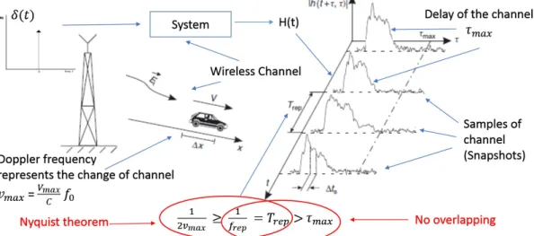
2.4 Sounding principle of a time-variant wireless channel. . . 29
2.5 Categories of channel sounder structures. . . 30
2.6 Baseband components + RF components channel sounding system. . . 30
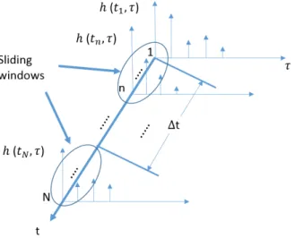
3.1 Sliding windows of APDPs moving along the time axis. . . 40
3.2 FSRs of the channel in high frequencies and low frequencies in the same environment. . . 43
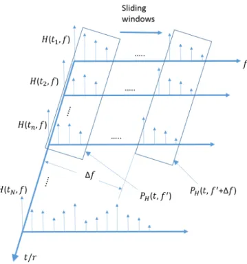
3.3 Sliding-windows of sub-APTFs moving along the frequency axis (we denotePH(t, f0) as thePH(t, f0) before averaging).. . . 44
3.4 Floorplan of the channel measurements in the basements. . . 47
3.5 Approximation of linear antenna subarrays. . . 47
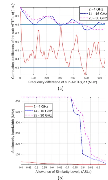
3.6 The FSRs of the channels, NLOS scenario: (a) correlation coefficients of the sub-APTFs and (b) stationary bandwidth vs. ASLs. . . 48
3.7 Correlation coefficients of the sub-APTFs in the LOS scenario. . . 49
3.8 Estimated MPCs in some of the sub-band channels from 2 to 4 GHz (LOS scenario). . . 51
3.9 Estimated MPCs in the sub-band channels from 28 to 30GHz (LOS scenario). . . 51
3.10 The FCFs of the sub-band channels, NLOS scenario: (a) within 2– 4 GHz band and (b) within 28–30 GHz band. . . 53
3.11 Cluster evolution in the frequency domain. . . 55
3.12 Tidal variation, as a metaphor to explain the cluster evolution in the frequency domain. . . 56
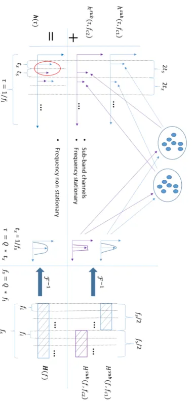
3.13 Example of adding up two sub-band channels as one FnS channel. . . . 63
3.14 Frequency consistent simulated sub-band CIRs, 28–30 GHz band. . . . 65
3.15 FnS channels, NLOS scenario, 28–30 GHz band: (a) simulated FnS-CIR and (b) measured FnS-FnS-CIR. . . 66
3.17 FCF approximations with 10 clusters in each simulated sub-band chan-nel, NLOS scenario, 28–30 GHz band.. . . 69
4.1 A-APDP method. . . 76
4.2 (a) Layout of an indoor office environment and definition of DCs in the LOS case and (b) sounder testbed. . . 77
4.3 (a) Angular correlation coefficients between the APDP at azimuth angle
φ= 0◦and the APDPs at other azimuth angles and (b) estimated ASRs on the azimuth plane with 90◦ elevation angle in the LOS case (ASL = 0.8), and (c) estimated ASRs based on (b) with different ASL levels from 0.4 to 0.9. . . 79
4.4 (a) RMS DSs and (b) K-factors estimated by the measured D-CIRs on the azimuth plane with the 90◦ elevation angle in the LOS case. . . 80
4.5 Three typical D-CIRs on the azimuth plane with 90◦ elevation angle based on the PPG levels in the LOS case. . . 81
4.6 Three typical D-CIRs in the LOS case: (a) D-CIR of Type 1, (b) D-CIR of Type 2, and (c) D-CIR of Type 3. . . 82
4.7 The DCs in the LOS and NLOS classes in the LOS case. . . 85
4.8 D-CIR hD(τ) can be modelled as the sum of responses from the
scat-terers at (φl, τl) with amplitudes al(φl, τl) in the angle range of a Rx
beam. . . 87
4.9 The modleing parameters of modified SV model. . . 89
4.10 (a) PDF of cluster excess delay and (b) cluster power decay rate esti-mated based on the D-CIRs in the NLOS class in the LOS case. . . 94
4.11 (a) PDF of ray excess delay and (b) ray power decay rate estimated based on the D-CIRs in the NLOS class in the LOS case. . . 95
4.12 The normal distributed FCPRs estimated based on the D-CIRs in the NLOS class in the LOS case. . . 96
4.13 The log-normal distributed cluster decay rates (normal distributed val-ues in dB) estimated based on the D-CIRs in the NLOS class in the LOS case. . . 96
4.14 A group of simulated D-CIRs of DCs in the LOS class. . . 102
4.15 (a) Comparison of the CDF of RMS DSs between the simulated DCs and measured DCs and (b) comparison of the correlation coefficients between the simulated DCs and the measured DCs on the azimuth plane with 90◦ elevation angle in the LOS class in the LOS case. . . 103
4.16 (a) Comparison of the CDF of RMS DSs between the simulated DCs and measured DCs and (b) comparison of the correlation coefficients between the simulated DCs and the measured DCs on the azimuth plane with 90◦ elevation angle in the largest group of NLOS class in the LOS case. . . 104
5.2 (a) Spherical angular correlation coefficients against azimuth and ele-vation angles in the LOS case and (b) estimated S-ASRs of mmWave channels in all directions (ASL = 0.8). . . 113
5.3 PPGs of D-CIRs in all directions in the LOS case. . . 114
5.4 RMS DSs estimated by D-CIRs in all directions in the LOS case. . . . 114
5.5 K-factors estimated by D-CIRs in all directions in the LOS case. . . 115
5.6 PPGs of D-CIRs in all directions in the NLOS case. . . 116
5.7 Procedure of modelling directional mmWave channels.. . . 122
5.8 (a) PDF of inter-cluster excess delay and (b) inter-cluster power decay rate based on the D-CIRs in the LOS state in the LOS case. . . 126
5.9 (a) PDF of intra-cluster/ray excess delay and (b) intra-cluster/ray power decay rate based on the D-CIRs in the LOS state in the LOS case.127
5.10 The normal distributed FCPRs estimated based on the D-CIRs in the NLOS state. . . 128
5.11 The log-normal distributed inter-cluster decay rates (data in dB follow normal distribution) estimated based on the D-CIRs in the NLOS state.128
5.12 (a) One simulated LOS state D-PDP hD,LOS(τ) and (b) the compari-son of the CDFs of RMS DSs between the simulated D-CIRs and the measured D-CIRs, LOS state, LOS case. . . 135
5.13 (a) One simulated NLOS state D-PDP hD,NLOS(τ), and (b) the
com-parison of the CDFs of RMS DSs between the simulated D-CIRs and the measured D-CIRs, NLOS state, LOS case. . . 136
6.1 The transverse energy intensity of a beam follows Gaussian distribution. There is a torch at up-right corner, the transverse energy intensity at the down-right corner, and the transverse energy intensity profile at the left hand side. . . 140
6.2 Construction of one Gaussian beam based on beamforming technology. 140
6.3 DGBs channels. . . 141
6.4 Estimated ASRs of mmWave channel from D-CIRs in different azimuth angles, ASL is 0.8. . . 144
6.5 Angular separated three typical D-CIRs in three Markov states (Tx rotates and Rx hold still). . . 144
6.6 DGBs channels in the located case. . . 146
6.7 DGBs channels in the dislocated case (shifting distance isd). . . 146
6.8 The DGBs overlapping area for both the located and dislocated cases. . 147
6.9 Synchronised DGBs channels (swing ranges ψTx = ψRx = 60◦, length
of vertical positioned slim object is 1 m, distance between Tx and Rx is 10 m, and the shifting distance d is 2 m for the dislocated case). . . . 147
6.10 Synchronised DGBs channels (swing ranges ψTx = ψRx = 60◦, length
of vertical positioned slim object is 3 m, distance between Tx and Rx is 10 m, and the shifting distance d is 2 m for the dislocated case). . . . 148
is 10 m, and the shifting distance d is 4 m for the dislocated case). . . . 148
6.12 Both synchronised and asynchronised DGBs channels (swing range ψTx = ψRx = 60◦, length of vertical positioned slim object is 1m, distance between Tx and Rx is 10 m, and the shifting distanced is 2 m for the dislocated case): (a) LOS states, and (b) NLOS states. . . 150
7.1 Directional dependent stationary distance for mmWave channels.. . . . 159
7.2 Split the channel environment into parts. . . 161
A.1 The distorted estimation of channel.. . . 164
2.1 Brief of mmWave channel measurements . . . 32
3.1 Size of FSRs in a NLOS scenario. . . 47
3.2 Parameters of sub-band channels (NLOS scenario, 2–4 GHz). . . 58
3.3 Parameters of sub-band channels (NLOS scenario, 28–30 GHz). . . 58
4.1 Estimated Statistical Parameters in LOS Case.. . . 93
4.2 Specific Statistical Parameters in LOS Case. . . 93
5.1 The numbers of state transitions in the LOS case. . . 119
3GPP Third Generation Partnership Project 4G Fourth Generation
5G Fifth Generation
5GCM 5G Channel Model for bands up to 100 GHz 5GPPP 5G Infrastructure Public Private Partnership 6G Sixth Generation
ACF Autocorrelation Function AoA Angle of Arrival
AoD Angle of Departure
ASL Allowance of the Similarity Level ASR Angular Stationarity Region
A-APDP Angular Averaged Power Delay Profile APDP Averaged Power Delay Profile
APTF Average Power Transfer Function AS Angular Spread
A2X Air-to-Everything
COST European Cooperative in Science and Technology CCF Cross-Correlation Function
CDF Cumulative Distribution Function CBSM Correlation Based Stochastic Model DC Directional Channel
DGBs Double Gaussian Beams D2D Device-to-Device
D-PDP Directional Power Delay Profile DS Delay Spread
eMBB Evolved Mobile Broadband FCF Frequency Correlation Function FCPR First Cluster Power Ratio FFT Fast Fourier Transformation FnS Frequency non Stationary FS Frequency Stationary
FSR Frequency Stationarity Region GBSM Geometry Based Stochastic Model
GSCM Geometry Based Stochastic Channel Model HF High Frequency
HST High-Speed Train HO Homogeneous Channel
IEEE Institute of Electrical and Electronics Engineers i.i.d. Independent and Identically Distributed
IMT International Mobile Telecommunication ITU International Telecommunication Union ITU-R ITU Radiocommunication Sector
LTE Long Term Evolution LTE-A LTE-Advanced LF Low Frequency LMS Land Mobile-Satellite LOS Line-of-Sight
LSP Large-Scale Parameters mmWave Millimetre Wave
mMTC Massive Machine-Type Communications
METIS Mobile and wireless communications Enablers for Twenty-twenty Information Society
MIMO Multiple-Input Multiple-Output MU-MIMO Multi-User MIMO
M2M Mobile-to-Mobile MPC Multi-Path Component NR New Radio
NLOS Non-LOS
omni-CIR Omni-Directional CIR
P-ASR Planar Angular Stationarity Region PDP Power Delay Profile
PDF Probability Density Function PPG Peak Power Gain
PTF Power Transfer Function PPG Peak Power Gain
QuaDRiGa QUAsi Deterministic RadIo channel GenerAtor RMS Root Mean Squire
S-ASR Spherical Angular Stationarity Region SV Saleh-Valenzuela
ToA Time of Arrival
UCA Uniform Circular Array
URLLC Ultra-Reliable and Low-Latency Communications UWB Ultra-Wide Band
V2V Vehicle-to-Vehicle V2X Vehicle-to-Everything V2I Vehicle-to-infrastructure VLC Visible Light Communication
WINNER Wireless World Initiative New Radio WSS Wide Sense Stationary
al amplitude of cluster
al,m amplitude of intra-cluster rays
c(t,4t) correlation coefficients in time domain
c(f0,4f) correlation coefficients in frequency domain
c(φ,4φ) angular correlation coefficient C[·] covariance operator
d shifting distance (Chapter6)
dt stationarity interval (stationarity region in the time domain) df stationarity bandwidth (stationarity region
in the frequency domain)
dφ angular stationary interval (stationarity region
in the angular domain)
dsep angular separation interval (Chapter 5)
exp[·]/exp(·) exponential operator E{·} statistical expectation
fco centre frequency of the o sub-band channels
F−1[·] inverse Fourier transformation
h(ti, τ) (omni-directional) channel impulse response H(ti, f) (omni-directional) channel transfer function
h(τ) (omni-directional) FnS channel impulse response (Chapter3)
hsub(τ, f
h (φi, τ) directional channel impulse response (Chapter 4) hD(φ
i, θj, τ) directional channel impulse response (Chapter 5) hD(τ) directional channel impulse response (short notation,
Chapter 4, 5, and 6)
hD,LOS(τ) directional channel impulse response in the LOS class/state
hD,NLOS(τ) directional channel impulse response in the NLOS class/state hOmni-d(τ) omni-directional channel impulse response (Chapter 4)
K LOS Rician factor
Kc1 first cluster power ratio (FCPR)
˜
Kc1 normal distributed FCPR
ln(·) logarithm operator
o sub-band channel index
O0 number of sub-band channels one cluster survives / number of D-CIRs one cluster survives (Chapter4)
p successful connection ratio between the Tx and Rx (Chapter 6)
Ph(ti, τ) (omni-directional) instantaneous PDP PH(ti, f) (omni-directional) instantaneous PTF Ph(t, τ) average PDP of n-snapshots
PH(t, f) average PTF along time axis PH(r, f) average PTF along spatial axis PhD(φi, τ) directional PDP (Chapter 4) PD
h (φi, θj, τ) directional PDP (Chapter 5) PD
h (φ, τ) average PDP of n D-CIRs (Chapter 4) PD
h (φ, θj, τ) average PDP of n D-CIRs (Chapter 5) Pl(fco) normalised inter-cluster power
Psurvival survival probabilities of the clusters
P1 probability of one-step transition matrix Pn n-step transition matrix
pdf(·) probability density function (PDF)
t time
V[·] variance operator [·]∗ conjugate operator
Greek:
βl,m random phases of intra-cluster rays γ intra-cluster ray power decay rate
/ flashing rate (Chapter 6) Γ inter-cluster power decay rate ˜
Γ log-normal distributed inter-cluster power decay rate ∆f frequency difference
∆t time difference
∆φ azimuth angle difference
τ1 compensation of delay interval between
the first cluster and the rest of the clusters
θ azimuth angle / beamwidth (Chapter 6)
θl(fco) inter-cluster angle
θl,m(fco) intra-cluster angle, ray angle θmean
l (fco) mean angle of cluster
λ rate parameter used to define survival probability
µk mean of normal distributed FCPRs
π limiting distribution
ρ apex angle
σk variance of normal distributed FCPRs στ(fco) delay spread
σθ(fco) standard deviation of inter-cluster angle τl delay of the lth Cluster
τl,m relative delay of themth ray within thelth Cluster τl(fco) inter-cluster delay
ψ swing range (Chapter 6)
Ω stationary solid angle (spherical angular stationarity region, Chapter5)
Chapter
1
Introduction
1.1
Background
1.1.1
The 5G Wireless Communication Systems and Beyond
Driven by new service innovations and new innovative applications, the demand for data traffic is greatly increased for the fifth generation (5G) wireless communication systems and beyond [1]. In order to meet these service demands, the telecommuni-cation industry is converging on a common set of 5G requirements compared to the fourth generation (4G) network that the 5G network should achieve 1000 times the system capacity, 10 times the spectral efficiency, energy efficiency and data rate, and 25 times the average cell throughput. The aim of 5G is “to connect the entire world and achieve seamless and ubiquitous communications between anybody, anything, wherever they are, whenever they need, by whatever electronic devices/services/networks they wish” [2]. The International Telecommunication Union (ITU) has classified 5G mobile network services into three categories as the envision of 5G: Evolved mobile broad-band (eMBB), Ultra-reliable and low-latency communications (URLLC), and Mas-sive machine-type communications (mMTC) [3]–[5]. With such great perspective, the fundamental and radical paradigm-shift of our traditional 4G Long Term Evolution
(LTE)/LTE-Advanced (LTE-A) wireless communication system is inevitable. The de-velopment of 5G leads to an overall re-thinking of cellular operational principles and architectures, network topologies, transmission technologies, and the analysis, design and optimisation methodologies.
In the networks upgrading of previous generations, both the access and core network are generally deployed at the same time. For the aim of 5G that connecting the entire world, the 5G network will be deployed with existing networks, such as the 4G LTE system. The standalone (SA) operation of 5G system and the non-standalone (NSA) integrated elements of different generations in different configurations are both under research and development [6]. The 3GPP has defined both a new 5G core (5GC) network and a new radio access technology called 5G new radio (NR) [6]. The specification of NR is subdivided into two frequency bands, FR1 is below 6 GHz band and FR2 is millimetre wave (mmWave) frequency band [7]. The development for the features and performance specifications of 5G continues. The academia and industry are working very closely towards the standardization of 5G around 2020. New fundamentals have been selected and formalized into standards in Release-15 (Phase 1) and Release-16 (Phase 2) by 3GPP [8]. Release-16 is in the middle of the specification development, aiming at freezing the physical layer part by March 2020. More 5G system enhancements will be set in Release-17, which is under development, scheduled for delivery in 2021.
The researches towards 5G are multi-fold. The approaches to enhance capacity/-data rate are mainly in the directions of more antenna, more bandwidth, and more cells. Correspondingly, massive multi-input-multi-output (MIMO) technology, mm-Wave technology, and network densification are the most promising technologies to meet the requirements of 5G mobile communication networks [2], [9] and very fruit-ful research results have been published both from academia and industry. There are other research areas related to 5G, such as visible light communications, network slicing [10], software-defined networks [11], full-duplex Communications [12], spatial modulation [13], network coding (polar coding [14]), new waveform (generalized fre-quency division multiplexing, refer to GFDM) [15], wireless caching [16], cloud and
virtualisation technologies, energy efficiency, etc. In the industry, development of 5G is being led by companies like Intel [17] and Qualcomm [18], Lenovo [19], Nokia [20], Huawei [21], Ericsson [22], and Samsung [23], etc. By the fall of 2018, the operators, such as AT&T, Verizon, and T-Mobile in the USA, EE in the U.K., Elisa in Finland, Vodafone in Spain, KT, LG U+, and SK Telecom in Korea, have announced the 5G trials and network launch plans start from the end of 2018 [24]. In the summer of 2019, the first commercial 5G networks in U.K. has been lunched [25], and China has issued the 5G frequency licenses to the main operators for initializing the construction of commercial 5G networks [26].
With the perspective of intelligent societies based on wireless communication sys-tems in the future, recent advances in machine learning infused with network edge intelligence is pushing the researches into the sixth generation (6G) wireless commu-nication systems. The latest insights and innovations from industry and academia on 5G and beyond has been presented and discussed in the first 6G summit, Levi Lapland, Finland, which paves the road for the coming of 6G [27].
1.1.2
The Brief of MmWave Communication
The mobile data traffic of smartphones and tablets has grown 4,000-fold over the past 10 years since 2005 [28]. If this trend continues, the traffic will globally reach 30.6 Exabyte (1018 bytes) per month by 2020 [29]. One approach to enhance the
capacity/data rate is more bandwidth. ITU radio communication sector (ITU-R) reported about 2 GHz spectrum requirements to accommodate such service demand at latest in 2020 [30]. It is obvious that this bandwidth is not available in the frequency bands used in current 4G mobile communications. The industry is looking at new spectrum in the range up to 100 GHz or higher, i.e., mmWave frequency range. It has been shown that the spectrum around up to 30 GHz and higher frequency range is much less crowded. There are about 1 GHz bandwidth resource available in 28 GHz and 38 GHz bands and 7 GHz bandwidth resource available in 60 GHz band (unlicensed) [31].
Figure 1.1: Attenuation vs. frequencies.
The studies from academia [32]–[34] and ITU-R have shown the feasibility of mm-Wave mobile cellular networks and the technical feasibility of international mobile telecommunication (IMT) in bands above 6 GHz [35]. 3GPP NR specification [7] has addressed the frequency range from 6 GHz to 100 GHz and bandwidth up to 400 MHz in mmWave communication. ITU-R selected candidates bands between 24.25 GHz and 86 GHz for IMT 2020, namely 5G cellular networks in 2015 [36]. Standard-ization activities for 5G have been kicked-off in ITU-R [37] and in 3GPP [38]. The envision [1], [29], [39] for 5G mmWave communication does not only include scenarios and the applications supported by current 4G communication, it also includes the new applications within the scope of eMBB, mMTC, and URLLC [40], such as vehicle-to-vehicle/infrastructure/everything (V2V/V2I/V2X) communication [41], [42], device-to-device (D2D) communication [43], mmWave air-to-everything (A2X) [44], high speed railway [45], shot-latency gaming and remote control [46], mmWave localiza-tion [47], mmWave WiFi [40], etc. Though there are some discussions about the health effect of mmWave communication [48], [49], the academia and industry are working closely together to bring mmWave communication to reality.
Ultra-high speed access and backhaul systems can be formed by using mmWave spec-trum together with network densification and massive MIMO [50]. The advantages are that mmWave signals have much shorter wave length. The antennas array with a large number of antenna elements can be packed within a compact size [32], [51] and the applications with large antenna arrays in the future mobile networks can be
Figure 1.2: Omni-directional propagation to directional propagation.
greatly enriched [52], [53]. Also, the beamforming technology based on large antenna arrays generates beams with narrow beamwidths. This enables higher security com-munication against eavesdropping/jamming and the reuse of spectrum in space [54]. There are many challenges in the design of mmWave communication systems. The high attenuation is the biggest issue of transmitting signals at mmWave frequencies. For example, in Fig. 1.1, the attenuation at 60 GHz is more than 100 times larger than those below 10 GHz. In order to compensate the high attenuation, beamforming technology based on large antenna array is considered as an enabling technology in mmWave communication [55] as shown in Fig.1.2. In [56], the investigation has shown that by using beamforming technologies [55] and other means to compensate the high attenuation, the mmWave communication over a few hundreds of meters or even a few kilometers is possible. However, controlling each antenna element of a large antenna array by a separate radio frequency (RF) chain is very complex, and the high-frequency power amplifiers (PAs) and RF chains with large bandwidth are very expensive and power consuming [57]. The redesign of corresponding RF/signal processing techniques is required, and the spectral efficiency and energy consumption/hardware cost need to be balanced [58].
Moreover, the radiation patterns with narrow main beams and side lobes are com-plicated to implement in practise (main beam gain is not constant) [54], especially, in beam misalignment cases during mmWave communications. Therefore, a robust alignment scheme of the Tx and Rx beams is required, and channel state feedback
and management to support directional beam search/steering will be vital [59], [60]. The state-of-the-art researches in this area are mainly as follows: adaptive beamform-ing [61], [62], hybrid antenna array [63], two layers of beam alignment [64], [65], beam switching [66], dual connectivity [67], beam training [68], intelligent beam search and tracking algorithms [69], etc.
1.2
Motivation
The very broad bandwidth and directional propagation are the main features of mm-Wave channels. The radio propagation mechanism and the channel characteristics of mmWave channels change dramatically from those of well-known conventional 3G/4G channels. Though plenty of mmWave channel measurements in different scenarios have been performed, the results of propagation properties, such as attenuation, the blocking effect, the large scale fading, delay spread (DS), and angle of arrival/angle of departure (AoA/AoD), etc., have been adopted in the latest developed standard mmWave channel models. However, those research results are mainly the expansion of former 3G/4G standard models by adding new additional components and extend-ing the frequency range of channel models to mmWave frequencies. In this case, some important mmWave channel properties may be overlooked following the inertia of classic approaches of channel models. An overall re-think of the mechanism in modelling mmWave channels is required.
For a thorough understanding of the mmWave channels, the studies of stationarity properties of mmWave channels are fundamental in the data analysis and modelling of mmWave channels. On one hand, the advantage of mmWave communications is the very broad bandwidth. The properties of a mmWave channel with broad bandwidth can be non-stationary in the frequency domain. On the other hand, the directional propagation properties of mmWave channel can also introduce another dimension of non-stationarity in the angular domain [70] due to the inhomogeneous channel environment. Currently, the non-stationarity in the time and spatial domains were investigated in the latest developed mmWave channel models, such as Quadriga [71]
and [72], [73]. The non-stationarity studies in the frequency and angular domains are rarely seen in the literature and current standard mmWave channel models.
In recent studies, there are plenty of beamforming alignment schemes proposed in the literature to support the Tx and Rx movement in mmWave communication [74]. The general mmWave channel properties may change due to using beam alignment schemes (beam behaviours), and the new channel characteristics of mobile-type mm-Wave channels according to various beam alignment schemes needed to be supported by standard channel models. Currently, the studies of mmWave channel properties affected by the beam alignment schemes are not sufficient, and the standard channel models have not included the properties of mobile-type mmWave channels according to various beam alignment schemes.
The motivation of researches during my Ph.D. study is to develop mmWave channel models which are able to model the key channel characteristics of mmWave channels with very broad bandwidth and directional propagation features. The development of those models is based on the data analysis of channel measurements and the stationar-ity studies of measured mmWave channels in the frequency and angular domains. The motivation also includes the studies of mmWave channels when Tx/Rx is in motion. It is based on the beam alignment scheme proposed in this thesis.
1.3
Contributions
The key contributions of the thesis are summarised as follows:
• Review recent advances on mmWave channel measurements, summarise and classify recent advances on existing stochastic models for mmWave channels.
Researches on a frequency non-stationarity and frequency non-stationary channel modelling
• Further develop the averaged power delay profile (APDP) methods, which en-ables to study the stationarity regions of channels in the frequency domain.
• Study the frequency non-stationary (FnS) properties of channels based on the measurements data. The variations of statistical parameters within the band-widths of FnS channels are addressed.
• Propose a novel FnS channel model for the channels with very broad bandwidths in both the sub-6 GHz and mmWave frequency bands. Ensure the frequency consistency of sub-band channels by cluster evolution in the frequency domain.
Researches on angular stationarity and directional mmWave channel modelling
• Develop an angular APDP (A-APDP) method to estimate the angular station-arity regions (ASRs) of channels in the angular domain.
• Three classes, namely, the light-of-sight (LOS), Non-LOS (NLOS), and outage classes, are utilised to classify the mmWave directional channels (DCs) based on measured directional channel impulse responses (D-CIRs).
• Propose a modified SV model to model the DCs in both LOS and NLOS classes. The consistency of DCs is ensured by cluster evolution in the angular domain.
• Synthesize the omni-directional CIR (omni-CIR) by DCs.
• Propose to model the directional mmWave channels by a Markov chain with three Markov states.
• Propose joint channel models to simulate the instantaneous directional mmWave channels based on the limiting distribution of Markov chain. The join channel models include a stationary channel model, a non-stationary channel model, and “zero” model.
Researches on mobile-to-mobile directional mmWave channels based on a novel beam-forming scheme
• Proposing a double Gaussian beams (DGBs) scheme for mobile-to-mobile mm-Wave communication.
• Using three Markov states to model the instantaneous directional mmWave channel under DGBs scheme.
• The connection ratios of each Markov state is studied.
1.4
Original Publications
This Ph.D. project has led to the following (potential) publications:
Refereed Journals Papers
1. Y. Tan, C.-X. Wang, J. Ø. Nielsen, G. F. Pedersen, and Q. Zhu, “A Novel Frequency Non-Stationary Channel Model for 5G and Beyond1,”IEEE Access 2019 (submitted for publication).
2. Y. Tan, C.-X. Wang, Q. Zhu, J. Huang, R. Feng, J. Bian, W. Zhong, and J. Yang , “A Novel GBSM For Wireless Directional MmWave Channels2,”IEEE Trans. Commun., 2019 (to be submitted).
3. Y. Tan, C.-X. Wang, J. Huang, R. Feng, J. Bian, and Q. Zhu, “Modeling Directional Millimeter Wave Wireless Channels by Markov States2,”IEEE Trans. Wireless Com-mun., 2019 (to be submitted).
4. Q. Zhu, Y. Yang, C.-X. Wang, Y. Tan, J. Sun, X. Chen, and W. Zhong, “Spatial correlations of a 3D non-stationary MIMO channel model with 3D antenna arrays and 3D arbitrary trajectories,”IEEE Wireless Commun. Lett., vol. 8, no. 2, pp. 512-515, Apr. 2019.
1The related contents have been recorded in the bi-monthly reports in 1st Quarter 2017 and 1st yearly report of EU H2020 Marie Sklodowska-Curie ITN project 5Gwireless, No. 641985. A video presentation can be found from www.youtube.com: Complementary Courses - Day 1 - ESRs giving presentations - Yi Tan (https://www.youtube.com/watch?v=5dcrFRjHroo&list= PLDxu3M0DpVdF9iqaKPmSN4oMM5Pf4zlvO&index=18)
2The related contents have been recorded in the bi-monthly reports and yearly reports in 2017 and 2018 of EU H2020 Marie Sklodowska-Curie ITN project 5Gwireless, No. 641985.
5. Q. Zhu, Y. Yang, X. Chen, Y. Tan, Y. Fu, C.-X. Wang, and W. Li, “A novel 3D non-stationary vehicle-to-vehicle channel model and its spatial-temporal correlation properties,” IEEE Access, vol. 6. pp. 43633–43643, Jul. 2018
6. Q. Zhu, H. Li, Y. Fu, C.-X. Wang, Y. Tan, X. Chen, and Q. Wu, “A novel 3D non-stationary MIMO channel simulator and hardware emulator,”IEEE Trans. Commun., vol. 66, no. 9, pp. 3865–3878, Sept. 2018.
Refereed Conferences Papers
1. Y. Tan, C. -X. Wang, Q. Zhu, Z. Zhang, Z. Wang, J. Huang, and R. Feng, “A novel beamforming scheme for mobile-to-mobile millimeter wave communications,” inProc. WSA’18, Bochum, Germany, Mar. 2018.
2. Y. Tan, J. Huang, R. Feng, and C.-X, Wang, “A study of angular stationarity of 5G millimeter wave channels,” inProc. ISWCS’18 Workshop, Bologna, Italy, Aug. 2017. 3. Y. Tan, C.-X. Wang, J. Ø. Nielsen, and G. F. Pedersen, “Comparison of stationarity regions for wireless channels from 2GHz to 30 GHz,” in Proc. IWCMC’17, Invited Paper, Valencia, Spain, Jun. 2017.
4. W. Qi. J. Huang, J. Sun, Y. Tan, C.-X. Wang, and X. Ge, “Measurements and modeling of human blockage effects for multiple millimeter wave bands,” in Proc. IWCMC’17, Valencia, Spain, Jun. 2017.
5. R. Feng, J. Huang, J. Sun, Y. Tan, C.-X. Wang, and S. Zhou, “Spatial cross-correlation properties of mmWave massive MIMO channels,” in Proc. IEEE/CIC ICCC’17, Invited Paper, Qingdao, China, Oct. 2017.
1.5
Thesis Organisation
Chapter2provides the literature review on the stochastic models for mmWave fading channels in the standard. The studies of two key features of mmWave channels, very broad bandwidth and directional propagation, in the current literature will be briefed,
as well as the studies of vehicular/mobile mmWave channels. In the end, the principle of channel measurement and recent advances on mmWave channel measurements will be reviewed.
Chapter 3 relates to the studies of frequency stationarity and frequency non-stationary channel modelling. It forms the main body of journal paper “a novel frequency non-stationary channel model for 5G and beyond.” This chapter first in-troduces the APDP method and shows the FSR studies of channels based on the measurement data. Then, it proposes a FnS channels models for modelling the chan-nels in both sub-6 GHz and mmWave frequency bands. The studies in this chapter relate to the features of very broad bandwidth of mmWave channels.
Chapter4relates to the studies of planar angular stationarity and directional mmWave channel modelling. It forms the main body of journal paper “a novel GBSM for wireless directional mmWave channels.” This chapter first introduces the A-APDP method and shows the planar ASR studies of channels based on the measurement data. Then, it proposes to model the directional mmWave channels based on the classification of LOS, NLOS, and Null classes. The studies in this chapter relate to the feature of directional propagated mmWave channels.
Chapter 5relates to the studies of spherical angular stationarity and modelling direc-tional mmWave channels based on Markov states. It forms the main body of journal paper “modeling directional mmWave channels based on Markov states.” This chap-ter first further develops the A-APDP method and shows the spherical ASR studies of channels based on the measurement data. Then, it proposes to model the directional mmwave channels based on Markov states. The studies in this chapter also relate to the feature of directional mmWave channels.
Chapter 6 relates to the studies of mobile-to-mobile directional mmWave channels based on a novel beamforming scheme. It forms the main body of conference paper “a novel beamforming scheme for mobile-to-mobile millimetre wave communications.” This chapter proposes a DGBs scheme used in mmWave communications when both Tx and Rx are in motion (beam alignment is required). The focus of this chapter is
the connection ratios of directional mmWave channels in each Markov state when the DGBs scheme is applied.
Chapter7is the conclusions of the works in this thesis. It also points out the potential future works in mmWave channel modelling.
Chapter
2
Millimetre Wave Channel Modelling:
Literature Review
2.1
Introduction
The wireless radio channels are the transmission medium to convey the information signals from Tx and Rx. The researches in this area play a fundamental role in the radio system design because all the studies in wireless communication areas are aiming to overcome the “bad” effects on the signals that are caused by the radio channels. The channel measurements and channel models are the methods to study the radio channels. The channel characteristics are analysed and estimated based on the channel measurement data, and they are modelled as references for system-level designs and evaluations. For the conventional 3G/4G wireless channels, the working frequencies are mainly below 6 GHz. For the mmWave channels, we consider the working frequencies are above 6 GHz and up to 100 GHz or even higher [55], [75]. The study of mmWave channels is a very hot topic. There are many universities, research institutes, and companies working in this field. We can find quite a few survey papers published in recent years [40], [54], [75], [76]. The contents in this chapter relate to the background information and general idea of mmWave channel
Figure 2.1: Categories of channel models.
measurement and modelling. Those can be considered as a reference/baseline for the research topics in this thesis.
In this chapter, the categories of channel models are introduced first. Then, the standard mmWave channel models and the latest development of mmWave channels are introduced. In the following, the background of channel measurements, channel sounders, and a short brief of mmWave channel measurements campaigns are intro-duced.
2.2
The Categories of Channel Models
The wireless channel models can be generally divided into three categories as in Fig. 2.1. The methods used in the development of those models can be sorted as (1) Deterministic channel model, (2) Stochastic channel model, and (3) Hybrid chan-nel model (combined stochastic model and map-based model).
2.2.1
Deterministic Channel Model
The typical deterministic channel models are site-specific models as one main branch in Fig. 2.1. It can be further resolved as (1) restored impulse responses and (2) ray tracing models. Restored impulse responses are acquired from channel measurements, they are the most direct way to present the wireless channels. All the channel measure-ment data recorded in the literature can be considered as this type of channel model. The ray tracing models are also recorded in form of channel impulse responses, which are acquired from the deterministic solution of Maxwell’s equations or some approxi-mations based on the geographical and morphological information of certain wireless scenarios [77]. Ray tracing models are used to complement time-consuming and ex-pensive measurement campaigns in the investigation of propagation characteristics, coverage, and system performance [78]–[80]. Though with the drawback that large computational efforts are required and the results are inherently less accurate, ray tracing models have been recognised as reliable tools to simulate accurate mmWave channel properties [81], [82]. This type of channel model method has been used as part of standard channel models, such as IEEE 802.15.3c [83], IEEE 802.11ad [84], MiWEBA [85], METIS [39], etc.
2.2.2
Stochastic Channel Models
Stochastic channel models, as another main branch in Fig. 2.1, have been developed for the purpose of fast system-level simulations (compare with ray tracing models) [54]. They are the most widely used channel models in the system level simulation. They are not designed to correctly predict the impulse response in one specific location, but they can be used to predict the probability density function (PDF) over a large area [77]. This kind of models relies on statistical observations of the channels with various measurements in different typical scenarios. The distributions of various channel characteristics are estimated from measurements. Stochastic channel model can be generally divided into two categories further: (1) correlation-based stochastic channel
model (CBSM or CSCM) and (2) geometry-based stochastic channel model (GBSM or GSCM).
The CBSM channel model describes the MIMO characteristics by correlation matrices. Its merit is the lower computational complexity compared with the channel models in other categories. It is widely used by system-level performance simulations. The well-known and widely used Kronecker model and Weichselberger model belong to this category [86]. The difference between those two models is that the Kronecker model considers the Tx and Rx are not mutually correlated, but the Weichselberger model could well present the joint correlation between Tx and Rx.
The GBSM channel models are more accurate than CBSM channel models, but they are much more computational complex. There are mainly two types of GBSM: (1) shape based GBSM and (2) irshape based GBSM. Most of the regular-shape based GBSMs are analytical models, such as the Clarke model [87] and those in [73], [88]–[91]. Typically, the scatters of the channels are distributed based on a geometrical shape, such as ring, ellipse, etc. with certain distribution density functions. In such an approach of modelling, all the channel parameters can be tracked and calculated geometrically. The feature of such models is that the ref-erence models of regular-shape based GBSM are the mathematical channel models based on the geometric calculation, and the approximation methods, such as exact Doppler, the Lp-norm method (LPNM), etc., are often used in the simulation model
to approximate the reference models. Compared with that, in the irregular-shape based GBSM, the positions of scatterers are following certain distributions and they are randomly located rather than located on a geometric shape in irregular-shape based GBSMs. The parameters used in the simulation models are estimated based on the data of real channel measurements in different scenarios. Therefore, most of the standard channel models are in this category, such as WINNER II/+ [92], [93], QuaDRiGa [71], COST2100 [94], etc., as well as mmWave channel models, such as 3GPP [95], METIS [39], mmMagic [29], 5GCM [1]. Note that, follow the stochstical model branch in Fig. 2.1, the irregular-shape based GBSM can be further divided into two branches: (1) system-level approach (most fast fading models of standard
Figure 2.2: Standard channel models and their family history.
models), (2) cluster-level approach (used in COST2100). More details can be found in [96].
Stochastic channel models are in constant development to adapt to the new features of wireless communication systems. From the topology in Fig.2.2[54], we can see that the leading research of channel models is following the developing line of 3GPP-SCM (SCM stands for spatial channel model) [97], WINNER-I/II/+ [92], [93], and then 3GPP-3D [98], and 3GPP-NR [95]. Those models have covered most of the aspects of wireless channels in various scenarios, which include network layout, the large-scale and small-scale parameters, channel scenario transition (channel segment, drop and time evolution), etc. Some Matlab codes are also available for reference from the websites of those projects. As to the other developing lines, they are not all-inclusive channel models, but they are prone to be developed for specific applications/scenarios of wireless communication, or using other approaches to better model the properties of wireless channels in certain aspects. For example, COST 2100 [94] focuses on
multi-user, distributed MIMO, and moving Tx/Rx scenarios in the 4G communication system. 1
2.2.3
Hybrid Channel Models
There is a combined stochastic and deterministic channel modelling approach, which is called a hybrid channel model in METIS [39], as the third main branch of channel models in Fig.2.1. Normally, in the procedure of modelling the channel, the locations of the base stations (BSs) and the user equipment (UE) have to be fixed on a map first. The path loss (PL) and shadowing are calculated based on the map, and random shadowing objects can be generated based on ray tracing modelling method, which explained in Section 2.2.1. Then, all other calculations are done by the stochastic model [39]. Hybrid modelling approach takes the merits from both the deterministic and stochastic models, and it is widely accepted in the modelling of mmWave channels. In the mmMagic project, it extends the existing QuaDRiGa channel model [71] by using the deterministic channel approach in the simulations [29], [99].
2.3
Modelling of MmWave Channels
European Commission is funding the projects about 5G communication within the perspective of Horizon 2020. The 5G infrastructure public private partnership (5GPPP) [100] is taking Europe’s leadership in standardizing 5G communications and the re-search of mmWave channels is one of the most important areas. The mmWave channel models developed inherit the spirit of WINNER family models and have included most of the aspects of mmWave channels in different scenarios. The methodologies, such as the stochastic channel modelling approach, ray tracing modelling approach, and the hybrid modelling approach, as shown in Fig. 2.1, are all adopted in the development of those models, such as 5GCM, IEEE 802.11ay [101], IMT 2020 [102], and New York University (NYU) wireless models [103]. The researches in this area are leading by
Figure 2.3: Comparison of 5G channel models.
Prof. Theodore S. Rappaport in NYU [81], [104]–[106] and the researchers in Samsung Electron., Co., Ltd. [55]. The universities and the companies that are also working on mmWave channel models are Lund University [31], [107], University of Texas [108], Electron. & Telecommun. Res. Inst (ETRI) South Korea [109], [110], HWU [111], Intel Corp. [112]–[115], Huawei Technologies Co., Ltd. [116], etc.
2.3.1
Standard MmWave Channel Models
There are quite a few standard channel models support mmWave channel scenarios. From Fig. 2.3 [117], we can see that MiWEBA, METIS, MCHFB (5GCM), 3GPP, mmMagic models can be used to model mmWave channels. In the comparison among those models based on the corresponding materials, we can find that there are some common channel measurements and modelling methods in different standard models, because those models are developed in parallel and the partners belong to one project also actively contribute to other projects. For example, the mmMagic project partners also contribute to 3GPP and IMT 2020 projects. However, each individual model
has unique contributions. The status/expectation of existing information on high-frequency channels can be found in the 3GPP-NR document “Study on channel model for frequency spectrum above 6 GHz” [95]. In this section, we only brief some highly cited standard mmWave channel models.
2.3.1.1 IEEE 802.11ad & IEEE 802.15.3c
IEEE 802.11ad [84] and IEEE 802.15.3c [83] models are the previously proposed mm-Wave channel models at 60 GHz frequency range. IEEE 802.11ad is a 3D model and IEEE 802.15.3c is a 2D model. They were developed for different channel scenarios. IEEE 802.11ad focuses on the modelling of the channels in WLAN (wireless local area networks) scenarios, such as conference room, living room, and cubicle environment. IEEE802.15.3c focuses on the modelling of the channels in WPAN (wireless personal area networks) scenarios, such as residential, office, library, desktop, and kiosk. Those models are all rooted in the cluster-ray modelling approach which is similar to that of Saleh-Valenzuela (SV) model [118], [119] and the amplitudes and the delays are de-scribed by certain statistical distributions. Though they were both developed based on the statistical parameters estimated from the measurements and ray tracing were used in the modelling, but they are not exactly the same as the hybrid METIS model regarding their modelling methodologies. For example, empirical statistical distri-butions are wildly used in the modelling of cluster delays and angles, etc. in the IEEE 802.11ad which is called “quasi-deterministic” model [120].
2.3.1.2 METIS
METIS channel models inherit the spirit of common channel model, such as WIN-NER family models. The models are developed based on extensive literature reviews, massive data analysis of real measurements, and ray tracing simulations. The mod-els developed are for overall 5G scenarios, which includes the characteristics of both massive MIMO channels and mmWave channels. METIS also classify the overall mod-elling methods by map-based models, stochastic models, and hybrid models. This is
very instructive for later developed channel models. The user needs to make the selec-tion if the target propagaselec-tion scenario can be modelled with more than one modelling methods. The model choice depends on the frequency range, accuracy, computational complexity, and simulation time (which depends mostly on the simulated system like the number of BSs and UEs). The key results of the METIS channel model investi-gations can be found from the specification in [39].2
In the comparison of METIS models, the map-based models are the most complete models covering most of the test cases, propagation scenarios, and the desired fre-quency range. Map-based mmWave channel models addressed the frefre-quency range up to 100 GHz and the bandwidths of mmWave channels up to 10% of the centre frequency can be supported. The stochastic model suits best to urban macro and mi-cro cell environments, including the outdoor to outdoor (O2O) and outdoor to indoor (O2I) scenarios. The hybrid model is a combination of both. It can be considered as a flexible and scalable framework to meet diverse channel modelling/simulation requirements [39].2
2.3.1.3 MmMagic
The mmMAGIC channel model is a geometry based stochastic model (GSCM/GBSM) comprised of baseline modelling framework and additional features that extend its accuracy and applicability. The features of model are the studies of ground reflection and blockage effects, building penetration loss, support of large bandwidths and large antenna arrays, and spatial consistency. There are more than 20 channel measurement campaigns conducted in various scenarios, such as UMi street canyon, UMi open square, office, airport check-in area and outdoor-to-indoor, across the frequency bands from below 6 GHz to up to 100 GHz (close the gap between the traditional cellular frequencies and mmWave frequencies). Specific measurements were performed to study the specular and diffused scattering, the impact of the ground reflection and blockage, and the frequency-dependent channel characteristics. 3
Specifically, a blockage model based on METIS work has been developed based on Kirchhoff’s diffraction formula and verified in the real measurements. The spatial consistency modelling procedure, which was initiated by 3GPP, has been investigated. A grid-based GSCM (partly based on METIS), using time-variant angles and cluster death and birth as the UE is moving, has been proposed. It is also an important feature to evaluate mobility and beam tracking. The small-scale fading characteristics caused by the diffused signal components have been investigated in the measurements related to the surface roughness of various building materials.3
2.3.1.4 3GPP models, above 6 GHz
The 3GPP models are general channel models which inherit the modelling methods used since the development of WINNER family models. It is a system-level channel model including all aspects of channel characteristics of all related large-scale and small-scale parameters. It also includes the time/cluster delay line (TDL/CDL) mod-els for the convenience of link level evaluations, and the channel model calibration is filed to provide a baseline for all the industry and academia institutes in the devel-opment of 3GPP channel simulators. For the latest develdevel-opment 3GPP model, that support the modelling of channels above 6 GHz, is normally called 3GPP-NR. The details of model objectives can be found from the specification in [95].
In 3GPP NR, there are stochastic models and map-based hybrid models developed to support mmWave channels. The scenarios the stochastic models support include urban micro (UMi)-street canyon and urban macro (UMa), UMii-open square, indoor-office, indoor- shopping mall, and rural macro (RMa). Except for modelling the channel characteristics related to path loss, LOS probability, penetration, fast fad-ing (small-scale model), etc., the specific characteristics of mmWave channels are modelled by adding additional components, such as oxygen absorption, blockage, cor-relation modelling for multi-frequency simulations. The map-based hybrid models are composed of a deterministic model (based on METIS work) and a corresponding
3Note that the marked contents are excerpts from mmMagic final report [29]. A subset of the proposed mmMAGIC features is implemented in QuaDRiGa v2.0 [71].
stochastic model mentioned before. By introducing a digital map into the simulation, it can be used for the evaluation and prediction of system performance taking the impacts of environmental structures and materials into consideration.4
2.3.2
Specific Characteristics of MmWave Channels
Since the working frequencies of mmWave channels are above 6 GHz (could up to 100 GHz or higher), there are some specific channel characteristics that are differ-ent from those of former convdiffer-entional 3G/4G channels. In the standard mmWave channel models, the specific mmWave channel characteristics are introduced by addi-tional components, such as those in chapter 7.6 of 3GPP-NR [95]: oxygen absorption (frequencies between 53 and 67 GHz), blockage effects, etc. Due to the limit of the thesis, we only make a summary on some of the important specific characteristics of mmWave channels investigated in the standard mmWave channel models.
2.3.2.1 Frequency Dependent Characteristics
In order to model the channel characteristics over the range of 6 GHz to 100 GHz work-ing frequencies, the frequency dependent parameters are introduced into the standard channel models. For example, in 3GPP-NR [95], antenna patterns, array geome-tries, system centre frequency and bandwidth, oxygen absorption, cluster powers, delay spread, and angular spreads are all considered frequency dependent. As well as 5GCM version 2.0 [1], it provides significant updates to large-scale and small-scale parameter modelling, including a newly proposed clustering algorithm and models, which capture frequency dependent parameters.
In the modelling of mmWave channels with multiple frequencies, for example, trans-mitting signals at both low frequency (LF) and high frequency (HF) channels, the studies of consistency and correlation between them are required. The correlation coefficient is used as the metric to study the correlation of signals in time/spatial