Abstract— In this paper, a robust control system with the fuzzy logic approach is proposed. Two linear controllers which have a good performance in the upper and lower operating points are designed in order to control a nonlinear deterministic system. The performances of linear controllers are investigated in different operating points. A fuzzy logic controller, generally preferred when the linear controllers are not able to control the system with a satisfactory performance, is examined for the nonlinear system in different operating points. The obtained results in the Matlab/SIMULINK environment show the efficiency of the proposed fuzzy controller for the nonlinear system without the readjustment of the control parameter for each different operating point.
Index Term— Fuzzy logic, nonlinear system, robust control.
I. INTRODUCTION
Since 1965, fuzzy set theory introduced by zadeh [1] has a great field of implementation in real engineering applications. A Fuzzy Logic Control (FLC) ensures an appropriate control methods for variety control problems because of providing an effective method for constructing linear and nonlinear controllers via the use of heuristic information [1,2]. It is very important to cope with parameter variations and external noises in many industrial plants [3,4]. A FLC can be preferred to ensure robustness against parameter variations and external disturbances since it permits the control law to change [5-8]. A FLC is also used to provide efficient control when the precise mathematical models of the plants are not obtainable or the closed loop control problems are very complex.
(Write the date on which you submitted your paper for review.) This work was supported in part by the U.S. Department of Commerce under Grant BS123456 (sponsor and financial support acknowledgment goes here). Paper
titles should be written in uppercase and lowercase letters, not all uppercase. Avoid writing long formulas with subscripts in the title; short formulas that identify the elements are fine (e.g., "Nd–Fe–B"). Do not write “(Invited)” in the title. Full names of authors are preferred in the author field, but are not
required. Put a space between authors’ initials.
F. A. Author is with the National Institute of Standards and Technology, Boulder, CO 80305 USA (corresponding author to provide phone:
303-555-5555; fax: 303-555-303-555-5555; e-mail: author@ boulder.nist.gov). S. B. Author, Jr., was with Rice University, Houston, TX 77005 USA. He is now with the Department of Physics, Colorado State University, Fort
Collins, CO 80523 USA (e-mail: [email protected]). T. C. Author is with the Electrical Engineering Department, University of Colorado, Boulder, CO 80309 USA, on leave from the National Research
Institute for Metals, Tsukuba, Japan (e-mail: [email protected]).
Fuzzy controllers are especially used for nonlinear control problems in the events of having no good performance of linear controllers or need to different linear controllers in the different conditions [9,10]. When the closed-loop system behavior changes in different operating point, the different control parameters may give an adequate output response in each point. Since a FLC system uses fuzzy sets which are described by membership functions, it can control the system with a satisfactory performance over the different operating point [11].
In this paper, a FLC is proposed to control a nonlinear deterministic system which has different behaviors in different operating points. The non-linear system can be controlled by using linear controller but it doesn’t provide good performance in every operating point and different linear controllers must be design for each point. Therefore, the FLC system can be preferred to ensure satisfactory performance in different operating points of the nonlinear deterministic system.
In the paper, mathematical equation of the nonlinear system is given in section-2, and the design of two linear controllers in two operating points is presented in section-3. Then, the design of the proposed fuzzy controller to provide good performance in different operating points is given in section-4. Simulation results are given in section-5 to illustrate the performance of the controller. Finally, in section-6, a conclusion summarizes the effectiveness of the proposed controller.
II. MATHEMATICAL MODEL OF THE CONTROLLED NONLINEAR
DETERMINISTIC SYSTEM
Let us consider a nonlinear deterministic system having different behaviors at different operating points:
1 2
2 2 2 1 1
1 2 100
x x
u x x x x x
(1)
where is the control input and , are the state variables. The output equation of the nonlinear system is given by
Fuzzy Control of a Nonlinear Deterministic
System for Different Operating Points
Gonca Ozmen Koca
1, Cafer Bal
21,2
Firat University, Technical Education Faculty Department of Electronics and Computer Science 23119 Elazig, Turkey
2
x
y
(2)The system described by equation (1) and (2) can be linearized [12] about the operating point in order to show how the system needs different linear controller at different operating points. The linearized system can be given by
u y s s y ref ) )( 2 ( 100 (3)
where is the desired output of the system which can be assumed as the output at operating point. It can be clearly seen from equation (3) that the different control action is required at different value of the because of changing system pole.
III. DESIGN OF LINEAR CONTROLLERS FOR TWO OPERATING
POINTS
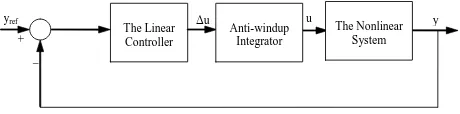
The block diagram of a linear control system for the nonlinear deterministic system is given in Fig.1. An anti-windup integrator structure is used to stop over-integration [13].
The operating region of system can be chosen as between 2
ref
y andyref 30. Different linear controllers are
designed for these upper and lower limit values of the operating region in order to obtain an output response without overshoot and a settling time (1%) less than 0.5s.
Linear controllers which are proposed for two operating points can be given by
) 25 . 0 )( 1 ( ) 997 . 0 )( 995 . 0 ( 30
2
z z z z
G (4.a)
) 5 . 0 )( 1 ( ) 9952 . 0 )( 84 . 0 ( 5
30
z z z z
G (4.b)
The first linear controller is designed to obtain satisfactory performance near to yref 2and the second linear controller similarly is designed to provide good performance near to
30
ref
y . The number of controllers can be increased to obtain satisfactory performance in each operating points between yref 2andyref 30. It is clear that the Fuzzy Logic Control can be proposed to compute accurate control action for every operating point by using membership functions instead of using different linear controllers at
different operating points.
IV. FUZZY LOGIC CONTROL
The block diagram of a FLC system for the nonlinear deterministic system is given in Fig.2. Input variables of the FLC are error , change-of-error and the output variable is . The error at using kth sampling time can be expressed
) ( ) ( )
(k y k y k
e ref (5)
where is the desired output and is the output of the system. The change of error can be given by
s T k e k e k
de( ) ( ) ( 1) (6)
where is the error value of the previous sampling time and Ts is the sampling period.
The membership functions for the input and output of the FLC system are shown in Fig.3. The ranges of the input membership functions are chosen according to maximum value of the error and change of error that may occur. The ranges of the output membership functions are determined by using back propagation algorithm [14]. These ranges are [-30 30] for e, [-12000 12000] for de and [-100 100] for the output variable u..
The rule base of the FLC system is given in Table 1 and derived from the relationship between inputs and output of the
system. The
k
th rule has the form of IF e is Fek ANDdeis Fdek THEN uis k
w (k1,...,M ) (7)
k e
F and Fdek are the interval type-1 fuzzy sets and wkis singleton output membership functions.
Fig. 2. The structure of a Fuzzy Control System
e
Fuzzifier Rule Base and
Inference
Defuzzifier Δu
Anti-windup Integrator
u The
Nonlinear System y de z-1 yref + _ FLC _ + 1/Ts
Fig. 1. The structure of a Linear Control System
The Linear Controller
Δu u y
In the defuzzifier, a crisp output is obtained from the resultant fuzzy set by using center of area (COA) method. This method can be expressed as
M
n n M
n n n u u
1 1
(8)
where un is the center of the nth implied output fuzzy set
and
n is the membership degree of u. Finally, the crisp output of the change of the control signal is obtained with defuzzification process. After this unit, an anti-windup integrator structure is used to stop over-integration [10].V. SIMULATION RESULTS
The simulation sampling period is choosen as sec
10 5 ,
2 3
x
Ts . Simulations are performed using a
Runge-Kutta fifth order integration method.
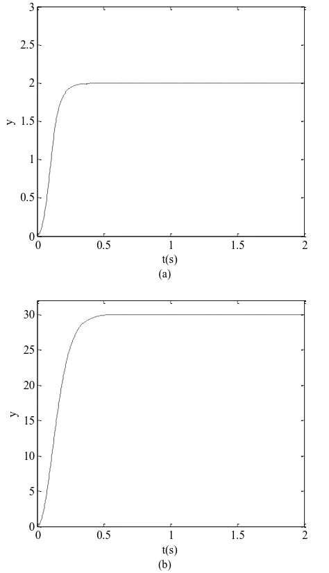
Firstly, the closed loop system given in Fig.2 is simulated for the well tuned linear control method. The responses of the output (y) are shown in Fig.4 and Fig.5. The designed two
linear controllers are used for two operating points (yref 2
and yref 30).
It is clearly seen from the figures that for yref 2 the first
linear controller and for yref 30 the second linear controller provide satisfactory performances. On the other hand, the oscillatory output response to a step reference yref 2 is obtained by using the second linear controller. In this way, as
seen from the Fig.5, the performance of the first linear controller for step reference yref 30 is not satisfactory. This means that different linear controllers should be design for every operating point to have a satisfactory performance for the nonlinear deterministic system.
Fig. 4. The output (y) to a step reference
0 0.5 1 1.5 2
0 0.5 1 1.5 2 2.5 3 3.5 4
t(s)
y
TABLEI
THE RULE BASE OF THE FLC SYSTEM
e de
NL NS ZO PS PL
NL NS Z PS
NL NL NL NS
NL NS NS Z
NL NS Z PS
NS Z PS PS
Z PS PL PL
PL Z PS PL PL PL
(a)
(b)
Fig. 3. a) Input membership functions b) output membership functions for the FLC system.
e,de -1 -0.3 0 1
NK YS PK PB
NB
1
0.3
0.5
-1 0 0.5 1 NK YS PK PB
NB 1
Δu
0 0.5 1 1.5 2
0 5 10 15 20 25 30
t(s)
y
Secondly, the FLC is proposed to ensure satisfactory performance in every operating point between the upper and lower operating limits. As shown in Fig. 3 triangular membership functions are used for input variables and singleton membership functions are used for the output variable respectively. The range of the membership functions are determined by using back propagation algorithm. The performances of the FLC system are illustrated in Fig.6 for
2
ref
y andyref 30.
Similarly, the performance of the proposed FLC system and
two linear controllers are illustrated for different operating points between the limit values in the Fig.7, Fig.8, Fig.9 and
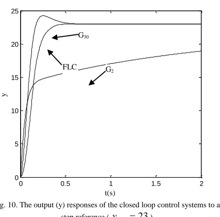
As seen in Fig. 7, 8, 9, 10, the proposed FLC system ensures satisfactory performance for the given operating
points while the linear controllers result in unacceptable control performance.
VI. CONCLUSION
This paper considers the controller design to obtain satisfactory performance at every operating point between the upper and lower operating limits for a nonlinear deterministic system. The system can be controlled by designing different linear controllers for different operating points but this is not practical because of time consuming. The fuzzy logic control approach is investigated to ensure good performance all over the operating region by using the error and the change of the
(a)
(b)
Fig. 6. The output (y) response of the closed loop FLC system to a step reference a)yref 2, b)yref 30
0 0.5 1 1.5 2
0 0.5 1 1.5 2 2.5 3
t(s)
y
0 0.5 1 1.5 2
0 5 10 15 20 25 30
t(s)
y
Fig. 7. The output (y) responses of the closed loop control systems to a step reference (yref 8)
0 0.5 1 1.5 2
0 2 4 6 8 10 12
t(s)
y
Fig. 8. The output (y) responses of the closed loop control systems to a step reference (yref 13)
0 0.5 1 1.5 2
0 2 4 6 8 10 12 14 16
t(s)
y
G2
FLC
G30
FLC
error as input variables. Thus, the proposed fuzzy logic control method provides robust control action instead of designing linear controller for each different operating point.
The performances of the controllers are comparatively given in the simulation results. The proposed control method is not only examined at limits of the operating points but also its performance is investigated at four points between the upper and lower limits in the operating region. The obtained results verify the robust control performance at every operating point for the proposed fuzzy logic controller.
REFERENCES
[1] L. A. Zadeh, “Fuzzy Sets, Information and Control”, 8 (3), pp. 338-353, 1965.
[2] K. M. Passino, “Fuzzy Control”, Addison Wesley Longman, 1998. [3] D. D. Driankov, H. Hellendoorn, and M. Reinfrank, “An Introduction to
Fuzzy Control”, Berlin-Heilderberg, Germany:Springer-Verlag, 1993.
[4] R. Palm, D. D. Driankov, and H. Hellendoorn, “Model Based Fuzzy Control”, Springer-Verlag, 1997.
[5] L. X. Wang, “A Course in Fuzzy Systems and Control”, Prentice Hall, 1997.
[6] J.M. Mendel, “Uncertain Rule-Based Fuzzy Logic Systems: Introduction and New Directions”, Upper Saddle River, NJ: Prentice Hall PTR, 2001. [7] J.J.E. Slotine, and W. Li, “Applied Nonlinear Control”, Englewood
Cliffs, NJ: Prentice-Hall, 1991.
[8] G. F. Franklin, J. D. Powell, and A. E Naeini, “Feedback Control of Dynamic Systems”, Addison-Wesley, 1994.
[9] B. J. Choi, S. W. Kwak, and B. K. Kim, “Design of a Single-Input Fuzzy Logic Controller and Its Properties”, Fuzzy Sets Sys., 106 , pp. 299-308, 1999.
[10] Z.H. Akpolat and G.M. Asher, “A practical approach to the design of robust speed controllers for machine drives”, IEEE Trans. on Industrial Electronics, 47(2), pp. 315-324, 2000.
[11] Z.H. Akpolat, G.M. Asher and J.C. Clare, “Equivalence of fuzzy and classical controllers: An approach to fuzzy control design”, 8th European Conference on Power Electronics and Applications (EPE’99), CD-ROM 90-75815-04-02, Lausanne, Switzerland, Sep., 1999. [12] Z. H. Akpolat, “Application of Fuzzy-Sliding Mode Control and
Electronic Load Emulation to the Robust Control of Motor Drives”, Phd Thesis, University of Nottingham, 1999.
[13] G. O. Koca, and Z. H. Akpolat, “Bulanık mantık ve erişim kuralı yaklaşımını kullanarak bir elektrikli aracın dayanıklı hız denetimi”, Gazi Üniversitesi Teknik Eğitim Fakültesi Politeknik Dergisi, 9( 2), pp. 93-103, 2006.
[14] M. Brown, and C. Harris, “Neurofuzzy Adaptive Modelling and Control”, Prentice Hall, 1994.
Gonca Ozmen Koca, received the Ph.D. degree in Electric and Electronic
Engineering Department of Firat University. Her interested areas are control of electrical drives, fuzzy logic, sliding mode control, intelligent control techniques and mechatronics systems.
Cafer Bal, received the B.Sc and M.Sc degrees in electronic and computer education from Firat University, Elazig, Turkey, in 1997 and 2002 respectively. He is currently working towards to the Ph.D degree in electrical and electronic engineering and he is a lecturer at the same university. He research interests include speed sensorless control of electrical drives, artificial neural networks and fuzzy control, educational tools and virtual laboratories.
Fig. 9. The output (y) responses of the closed loop control systems to a
step reference (yref 18)
0 0.5 1 1.5 2
0 2 4 6 8 10 12 14 16 18 20 22
t(s)
y
Fig. 10. The output (y) responses of the closed loop control systems to a
step reference (yref 23)
0 0.5 1 1.5 2
0 5 10 15 20 25
t(s)
y
G30
FLC G2 G30