19
ISSN (e): 2250-3021, ISSN (p): 2278-8719
Vol. 09, Issue 10, October. 2019, Series -III, PP 19-26
Implementation of Grid Connected Solar System Using Cascaded
Eleven Level H-Bridge Multi-Level Inverter
Aryan
1, Risha Dastagir
21Research scholar, Department of Electrical and Electronics Engineering, Trinity Institute of Technology &
Research, Bhopal, India
2Assistant Professor at Department of Electrical and Electronics Engineering, Trinity Institute of Technology &
Research, Bhopal, India
Received 07 October 2019; Accepted 23 October 2019
Abstract: Multi-functionality in converters are drawing attention of researchers, since it is the main link of
grid tied solar system. A lot of ongoing research has been reported in literature for auxiliary services on power quality improvement through multi-functional grid-tied (MFGT) converters. These converters can perform dual work of interfacing solar system with the grid and also conditions the power at point of common coupling. The state-of-the-art of the converter is its design feature which optimally achieve the multi-functionality, hence presents a cost effective solution to power quality issues. A Grid connected solar system for radial distribution system is designed, which is capable of injecting active power into the grid with its inherent advantages to mitigate the Power Quality Issues.I.
INTRODUCTION
As the conventional energy sources are rapidly depleting and the demand of the electricity is increasing day by day as the world is moving towards advancement, this leads to develop alternatives for fulfilling the energy requirement. Hence the most promising solution is the use of renewable energy sources [1]. Most reliable type of the renewable energy i.e. Solar Energy is utilized for powering utility in the proposed work of this thesis. Using Solar Photovoltaic Array as the primary source, a model is developed and simulated in the MATLAB-Simulink, extracting the solar energy in the form of electrical energy. Output of the array is interfaced to the conventional dc-ac converter to get the AC voltage [2]. For feeding the single phase utilities, a two level voltage source inverter is interfaced at the output terminals of the PV array to get the pure sinusoidal output voltage, but the low Total Harmonic Distortion (THD) generated is not within the standard limits. To reduce THD filter is used with two level voltage source inverter. On the other hand multilevel is first choice because it gives low THD AC output voltage without the use of filter [3].Many efforts has done to improve the performance of the system with minimum losses, distortion and as possible as the maximum efficiency by using different topologies of multilevel inverter and with different levels. In this paper a MFGT inverter is designed the system is integrated to grid and to mitigate various power quality issues like voltage regulation, harmonic reduction, real and reactive power management etc. has been discussed [4,5].
II.
SOLAR ENERGY GENERATION SYSTEM
The smallest element of solar energy generation system is Photo cell. Solar cell (Fig-1) is basically a semiconductor look like thin film or disc which is when exposed to sunlight produces voltage or current. When solar cells are laminated between a clear super-strate (glazing) and encapsulating substrate, they are termed as solar panel or module and the combinations of more than one module in series or parallel is called as solar array [6,7].
The power produced by the PV array can be given as; Ppv= VpvIpv+ VdcIpv
Where Ppv solar output power, Vpv Solar output voltage, Ipv solar output current, Vdc DC bus voltage.
Figure-1 Solar cell
III.
GRID-TIED SOLAR SYSTEM
The two important issues of (Grid Tied Inverters) GTIs are efficiency and low cost are [10]. They are broadly two type of GTIs namely; single-stage (SS) and multiple-stage. Because the more stages reduce the efficiency of a GTI much more, a multiple-stage GTI mainly has two stages. In SS single converter (Fig. 2) take care of both DC/DC as well as DC/AC conversion. While two-stage GTI is comprised of a DC/DC stage and a DC/AC stage, as depicted in Fig. 3. SS and DS GTIs have their own advantages and disadvantages, so it is hard to say which is better [11, 12]. They are all implemented in different suitable occasions. Generally, small-capacity-scale grid-connected systems are more like to use DS GTIs due to their flexible feature. However, a big-capacity-scale system mainly uses SS GTIs for their high efficiency and reliability.
DC-AC converter
MPPT
Z
L
Local Loads Control
Algorithm Zc
PV array
PCC
GRID
Figure-2 Grid tied Single-Stage solar system.
DC-DC converter
MPPT
Z
L
Local Loads Control
Algorithm Zc
PV array
PCC
GRID
Inverter
21
IV.
PROPOSED WORK
A PV system is designed, 50 parallel strings and 10 Series-connected modules. The rated capacity of the PV panel is 100 KW. To obtain the constant DC output from Solar system a DC-DC boost converter is designed with switching frequency 3Khz. The output voltage of the boost converter is approx. 100 V.To integrate the PV system with the grid a DC/AC inverter is simulated. The inverter is designed using 11-level Cascaded Multilevel Inverter (CHB-MLI) which is synchronized using PLL and PI controller.A MATLAB-Simulink model of the solar panel with 10KW rating has been developed whose DC output is regulated using DC-DC boost converter.To design a DC/AC converter a 5 level inverter is designed whose pulse width modulation technique is designed using level shifted carrier modulation technique.One side of the converter is connected to the synchronized AC output of the PV system and other side to the grid. The system is synchronized with the grid using PI controller and Phase Lock Loop.The parameter considered in designing the proposed system is presented in table 1 and table 2.
Table-1 Component and rating used in the PI controller.
Components Ratings
R load 124 ohms
RL load 115 ohms and 182mH
Switching frequency 10khz
LC filter 1e-3 H and 1e-6 F
Frequency=50 Hz 0.96mH
Input voltage 450 V
PI gains Kp = 0.04; Ki = 500
Table-2 System parameters for 10 KW solar system with converter Parameters
Parameter Values
Switching frequency 5kHz
Cdc 12000e-6 F
L1 5e-3 H
Inverter parameter
Effective nominal voltage of the utility (RMS) VS 415 V Nominal utility grid frequency fS 50Hz
Switching frequency of the converters fch 30khz
inductance of filter 100e-3 H
Series resistance converter 0.01 ohms Capacitances of the parallel filters 1000e-6F Resistances of the converter filter 0.01 ohms
DC-bus voltage Vdc 100V
V.
RESULT AND DISCUSSION
Figure 4 Output voltage of 11 level CHB-MLI single phase.
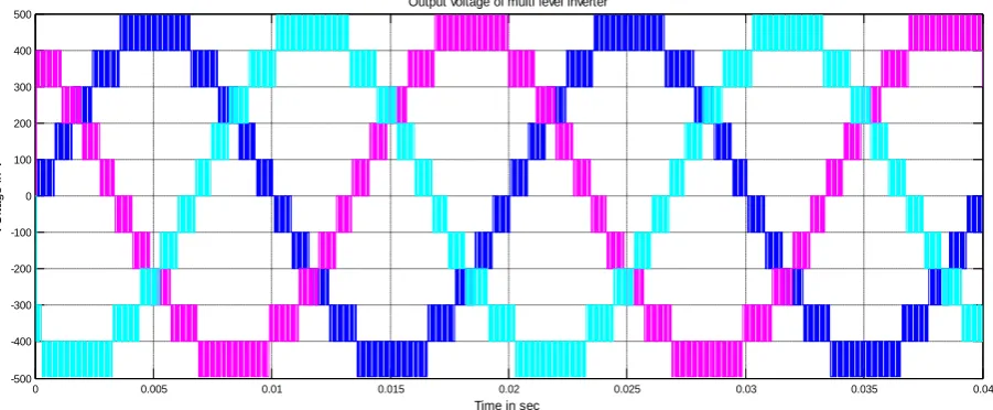
Figure 5 Output Voltage of 11-level three phase CHB-MLI
Figure 6 Output Voltage of Solar system inverter side at balanced linear load with proposed topology
0 0.005 0.01 0.015 0.02 0.025 0.03 0.035 0.04
-400 -300 -200 -100 0 100 200 300 400
Voltage waveform
0 0.005 0.01 0.015 0.02 0.025 0.03 0.035 0.04
-500 -400 -300 -200 -100 0 100 200 300 400 500
Time in sec
V
O
lt
a
g
e
i
n
V
Output voltage of multi level inverter
0 0.1 0.2 0.3 0.4 0.5 0.6 0.7 0.8 0.9 1
-400 -300 -200 -100 0 100 200 300 400
Time in sec
V
ol
ta
ge
in
V
23
Figure 7 Output Current of Solar system inverter side at balanced linear load with proposed topology
Figure 8 Output voltage of Solar system grid side at balanced linear load with proposed topology
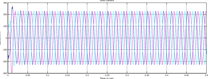
Figure 9 Output current of Solar system grid side at balanced linear load with proposed topology
0 0.05 0.1 0.15 0.2 0.25 0.3 0.35 0.4 0.45 0.5
-1500 -1000 -500 0 500 1000 1500
Time in sec
C
u
rr
e
n
t
in
A
Converter current
0.05 0.1 0.15 0.2 0.25 0.3 0.35 0.4 0.45 0.5
-400 -300 -200 -100 0 100 200 300 400
Time in sec
V
o
lt
a
g
e
i
n
v
o
lt
s
Grid voltage
0 0.05 0.1 0.15 0.2 0.25 0.3 0.35 0.4 0.45 0.5
-50 -40 -30 -20 -10 0 10 20 30 40 50
Time in sec
C
ur
re
nt
in
A
Figure 10 Output current of Solar system converter side at balanced non-linear load with proposed topology
Figure 11 Output current of Solar system grid side at balanced non-linear load with proposed topology
The THD analysis of the output voltage waveform is carried out for unbalanced linear loading and balanced non-linear loading whose comparative analysis is presented in Table-3. From the table it is clear that the proposed converter topology is compatible to follow grid code for grid connected operation of solar panel. It not only maintains the voltage profile but also eliminate the harmonic content in load current. Hence the topology can be applicable for bulk power integration from solar panel wth the grid to improve power quality of the system.
Table-3 Comparison of THD for output voltage using different PWM techniques
THD analysis of
Proposed work Conventional
topology
Proposed work Conventional topology
unbalanced linear loading balanced non-linear loading
Supply voltage
0.00 3.6 0.05 4.2
Load current 2 2.4 4.4 27.6
Inverter current
0.09 3.1 1.8 10.8
0 0.05 0.1 0.15 0.2 0.25 0.3 0.35 0.4 0.45 0.5
-1500 -1000 -500 0 500 1000 1500
Time in sec
C
ur
re
nt
in
A
Converter current
0 0.05 0.1 0.15 0.2 0.25 0.3 0.35 0.4 0.45 0.5
-300 -200 -100 0 100 200 300
Time in sec
C
u
rr
e
n
t
in
A
25
phase two stage SPV energy conversion system has been implemented in MATLAB. Static and dynamic performances of the system were evaluated under various modes of operation of grid voltage conditions.The performance of the multifunctional VSC has been demonstrated for harmonic elimination
REFERENCES
[1]. Dincer. ―Renewable energy and sustainable development: a crucial review‖, Renewable and Sustainable Energy Reviews 2004 (June (2):157–75.
[2]. Martı´nez, Dı´az de Basurto P, Martı´nez I, Ruiz P. ―European Union’s renewable energy sources and energy efficiency policy review: the Spanish perspective‖, Renewable and Sustainable Energy Reviews 2009;13(January (1)):100–114 I.
[3]. EREC-2005. "European Renewable Energy Council".Available at <http://www.erec.org/renewable-energy/photovoltaics.html>.
[4]. M. Hosenuzzaman, N. A. Rahim, J. Selvaraj, M. Hasanuzzaman, A. B. M. A. Malek, and A. Nahar, ―Global prospects, progress, policies, and environmental impact of solar photovoltaic power generation,‖ Renewable & Sustainable Energy Reviews, vol. 41, no. 0, pp. 284–297, Jan,2015.
[5]. S. J. Steffel, P. R. Caroselli, A. M. Dinkel, J. Q. Liu, R. N. Sackey, and N. R. Vadhar, ―Integrating solar generation on the electric distribution grid,‖ IEEE Transactions on Smart Grid, vol. 3, no. 2, pp. 878–886, Jun. 2012.
[6]. J. Kwon, et al. "Photovoltaic Power Conditioning System With Line Connection", IEEE Transactions on Industrial Electronics, vol. 53, no. 5, pp. 1048-1054, 2006.
[7]. W. L. Yu, et al. "A DSP-Based Single-Stage Maximum Power Point Tracking PV Inverter", in Proc. of APEC, vol. 25, pp. 948-952, 2010.
[8]. A. Pandey, et al. "A simple Single-Sensor MPPT Solution". IEEE Transactions on Power Electronics, vol. 22, no. 6, pp. 698–700, 2007.
[9]. J. Kwon, et al. "Photovoltaic Power Conditioning System With Line Connection", IEEE Transactions on Industrial Electronics, vol. 53, no. 5, pp. 1048-1054, 2006.
[10]. M. G. Villalva and J. R. Gazoli, ―Comprehensive approach to modeling and simulation of photovoltaic arrays,‖ IEEE Trans. Power Electronics, vol. 24, no. 5, pp. 1198–1208, 2009.
[11]. R.-J. Wai, W.-H.Wang, and C.-Y.Lin, ―High-performance stand-alone photovoltaic generation system,‖ IEEE Tran. Ind. Electron., vol. 55, no. 1, pp. 240–250, 2008.
[12]. V. R. Kolluru, K. Mahapatra, and B. Subudhi, ―Development and implementation of control algorithms for a photovoltaic system,‖ in Students Conference on Engineering and Systems (SCES’13), pp. 1–5, IEEE, 2013.
[13]. A. Mousavi, P. Das, and G. Moschopoulos, ―A comparative study of a new zcs dc–dc full-bridge boost converter with a zvs active-clamp converter,‖ , IEEE Trans. Power Electronics, vol. 27, no. 3, pp. 1347– 1358, 2012.
[14]. J.-H. Su, J.-J.Chen, and D.-S.Wu, ―Learning feedback controller design of switching converters via matlab/simulink,‖ IEEE Trans. Education, vol. 45, no. 4, pp. 307–315, 2002.
[15]. R.V. Rao, V.J. Savsani, D.P. Vakharia, Teaching–learning-based optimization: anovel method for constrained mechanical design optimization problems, Com-put. Aided Des.43 (March (3)) (2011) 303– 315, ISSN 0010-4485.
[16]. R.V. Rao, V.J. Savsani, D.P. Vakharia, Teaching–learning-based optimization: anoptimization method for continuous non-linear large scale problems, Inf. Sci.183 (January (1)) (2012), ISSN 0020-0255. [17]. T. Niknam, R.A. Abarghooee, M.R. Narimani, A new multi objective optimiza-tion approach based on
TLBO for location of automatic voltage regulators indistribution systems, Eng. Appl. Artif. Intell. 25 (2012) 1577–1580.
[18]. P. Kumar Roy, Teaching–learning based optimization for short-term hydro-thermal scheduling problem considering valve point effect and prohibiteddischarge constraint, Electr. Power Energy Syst. 53 (2013) 10–19.
[19]. R. Faranda, S. Leva, and V. Maugeri, ―MPPT techniques for PV systems: Energetic and cost comparison,‖ in Proc. PESGM, 2008, vol. 9, pp. 1–6.
[20]. M. C. Cavalcanti, K. C. Oliveira, G. M. S. Azevedo, and F. A. S. Neves, ―Comparative study of maximum power point tracking techniques for photovoltaic systems,‖ Eletrôn.Potência, vol. 12, pp. 163– 171, 2007.
[22]. Rodriguez P, Timbus AV, Teodorescu R, Liserre M, Blaabjerg F. ―Flexible active power control of distributed power generation systems during grid faults. IEEE Transactions on Industrial Electronics 2007; 54(5): 2583–92.
[23]. Roscoe AJ, Finney SJ, Burt GM. ―Trade-offs between AC power quality and DC bus ripplefor3-phase3-wireinverter-connected devices with in microgrids. IEEE Transactions on Power Electronics 2011; 26(3): 674–88.
[24]. Peng FZ, Akagi H, Nabae A. ―A new approach to harmonic compensation in power systems—a combined system of shunt passive and series active filters. IEEE Transactions on Industry Applications 1990; 26(6): 983–90.
[25]. Y. Yorozu, M. Hirano, K. Oka, and Y. Tagawa, ―Electron spectroscopy studies on magneto-optical media and plastic substrate interface,‖ IEEE Transl. J. Magn. Japan, vol. 2, pp. 740-741, August 1987 [Digests 9th Annual Conf. Magnetics Japan, p. 301, 1982].
[26]. Fujita H, Akagi H. ―Voltage-regulation performance of a shunt active filter intended for installation on a power distribution system‖. IEEE Transactions on PowerElectronics2007; 22(3):1046–53.
[27]. Lee TL, Li JC, Cheng PT. ―Discrete frequency tuning active filter for power system harmonics‖. IEEE Transactions on Power Electronics 2009; 24(5): 1209–17.
[28]. Ghosh A, Ledwich G. ―Compensation of distribution system voltage using DVR‖. IEEE Transactions on Power Delivery 2002; 17(4):1030–36.
[29]. Mahdian poor FM, Hooshmand RA, Ataei M. ―A new approach to multi-functional dynamic voltage restorer implementation for emergency control in distribution systems‖. IEEE Transactions on Power Delivery 2011; 26 (2): 882–90.