ISSN (e): 2250-3021, ISSN (p): 2278-8719
Vol. 07, Issue 09 (September. 2017), ||V2|| PP 14-21
EnergyStorage Using MnO
2Supercapacitor Electrode
*
M.M.El-Zaidia, A.H.Khafagy,S.Hassan and M.Z.Zaki
Physics Department, Faculty of science, Menoufia UniversityShebeen El-Koom, Egypt Corresponding Author: M.M.El-Zaidia
Abstract
: The deposition of MnO2on stainless steel substrate was carried out using potentiostatic (PS) andgalvanostatic (GS) deposition methods. Both deposited layers were found to be amorphous in nature. The SEM micrographs confirm this result. The I-V curves of the constructed supercapacitor show that the maximum and average stored electric power were 18 and 6.2 watt using PS deposition method. These values were independent on the voltage scan rate after 1000 cycle. The stored electric energy using PS was nearly one and half that stored using GS.The values of the stored energy were 91 and 73 joules using PS and GS, respectively. The maximum specific capacitance of the constructed supercapacitor was 389 and 327 Farad/gram for PS and GS respectively.
The time constant of charge periods were 5x10⁻³ S, and 6.02x10⁻³ S, for both PS and GS films respectively, but
the time constant for the discharging period for both of PS and GS films was the same,and has the value
1.02x10⁻³ seconds. The Nyquist plots of deposited MnO2 films show features of porous electrodes. This means
that their impedance are resistance at high frequency and capacitive at low frequency.
Keywords
: Crystalline; Amorphous; electric power; energy storage; electric impedance.--- --- Date of Submission: 14-08-2017 Date of acceptance: 13-09-2017 --- ---
I.
INTRODUCTION
Nowadays the energy crisis in the world increase, so world makes great attention to use of renewable energy sources and developing energy storages technologies. Energy storage systems are the way to manage the
discontinues nature of renewable sources1. One of these systems is supercapacitor known also ultracapacitor or
electrochemical capacitor which has high energy density, high power, short charge time, high safety, long cycle
life and high efficiency2-6. There are two main categories of supercapacitor depending on active electrode
material, double- layer capacitor where carbon is the base active material; pseudo-capacitor where conducting
polymer or transition metal oxide is the active electrode3, 4, 6, 7. Metal oxides are used because they have
characterized properties like high conductivity and high specific capacitance1, 8 such as RuO29, 10,IrO211,MnO212,
13
,NiO, Co2O3, SnO2, V2O5,or MoOx
1
. However most effective are Ruthenium and manganese oxides1, 14. But
RuO2 is toxic and expensive4 unlike MnO2 is abundant, eco-friendly and has promising electrochemical
features15-17. Electrodeposition of manganese dioxide thin film can be obtained by anodic or cathodic
technique18. Anodic electrochemical deposition method of MnO2 is commonly used18. Manganese dioxide thin
film is generally produced by anodic deposition onto metallic conductive substrate using acidified MnSO4
solution. However, this method usually leads to the dissolution of the conductive substrate or build up an insulating oxide layer at the active oxide/substrate interface. Many techniques can be used for anodic deposition
such as, potentiostatic, galvanostatic, potentiodynamic, and pulse deposition18, 19.The aim of the present work is
tostudy the electrochemically deposit thin films of MnO2 on stainless steel substrategrade(304)as a current
collector by anodic electrochemical deposition method using manganese acetate solution. This is to avoid the oxidation problems in acidic medium and applying both the potentiostatic and galvanostatic techniques, as a
comparison study on the structural and electrochemical properties of deposited MnO2 for supercapacitor
application.
II.
EXPERIMENTAL
2.1 Electrochemical deposition of MnO2 films
Stainless-Steel(SS) foils commercially available (type 304) of thickness 0.175mm were cut as samples
of 1× 2 cm2 each to be used as working electrodes for the electrochemical deposition. The samples were first
etched in Hydrochloricacid, 38% for 10 minutes, and then washed with distilled water and air dried. MnO2 thin
films were anodically electrodeposited from 0.25 M (CH3COO)2Mn.4H2O solution bybothpotentiostatic(PS) and
galvanostatic(GS) conditions at 1volt and 1mA/cm2, respectively. The estimated mass loading of thedeposited
MnO2 film was 300 µg/cm2, which controlled by adjusting the total charge passed through the electrode during
2.2 Structure and Electrochemical characterization of MnO2/SS electrode:
The structural and morphological characteristics of prepared MnO2 films were examined by X-ray
diffraction (XRD) and scanning-electron microscope (SEM), respectively. The X-ray diffraction pattern of the filmswas recorded usingautomated and computerized Philips (model PW1051) supplied with monochromatic
CuKα radiation source (λ=1.541Å), while surface morphology of electrodeposited films was investigated using
(Quanta 250 FEG) Scanning electron microscope.
All electrochemical deposition and measurements were performed by conventional three electrode system using SP-150 potentiostat /galvanostat device in an electrochemical cell with stainless steel substrate as a working electrode, Ag/AgCl (NaCl saturated) as a reference electrode, Pt wire as a counter electrode, and 0.5 M
Na2SO4 solution as the characterization electrolyte. The deposited MnO2 thin films were tested for
supercapacitor application by studying the cyclic voltammetry, charge-discharge, and electrochemical impedance spectroscopy (EIS) measurements. Cyclic voltammetry (CV) tests were conducted in a potential range of 0-1 V at scan rates of 10-100 mV/s. Galvanostatic charge/ discharge cycling was conducted at current
density of 1-10 mA/cm2 between 0 and 1 volt.EIS data were collected at alternating current root mean square
voltage amplitude 10 mV in a frequency range of 100 kHz-10MHz.
III.
RESULTS AND DISCUSSION
3.1. Structure studiesX-ray studies
Fig(1)shows, the appearance of x-ray sharp peaks, reflecting the crystalline structure of the bare
stainless steel (SS) substrate. After the potentiostatic deposition of MnO2 on stainless steel substrate, the x- ray
diffraction pattern was recorded once again.
20 40 60 80
0 50 100 150 200 250 300
In
te
n
si
ty
(a
rb
it
ra
ry
u
n
it
)
2 Theta, degrees
SS MnO
2 (PS)
Fig.(1)XRD patterns of etched bare SS and potentiostatically deposited MnO2/SS.
The obtained x- ray pattern confirms the amorphous nature of the deposited MnO2 layer. The detected
x-ray peaks roots which are superimposed on the pattern ofMnO2 at the same location of SS crystalline peaks
may be due to higher order of x-ray reflections form SS substrate. This confirms the amorphous nature of the PS deposited film. However, the amorphous nature of the deposited metal oxide film is generally required for obtaining electrodes with large surface area for supercapacitor purposes,where the amorphous phase can give
the chance for ions to penetrate the bulk active material2, 20.
3.2.SEM Studies
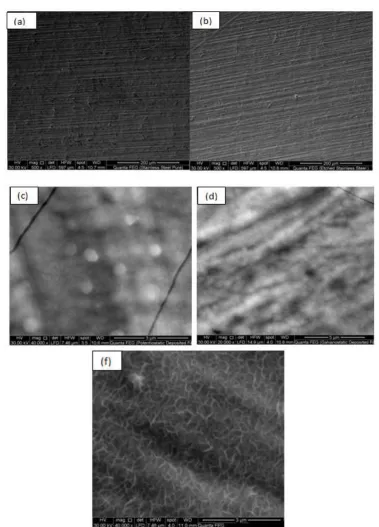
Fig (2) (a-f) shows the SEM surface morphological micrographs for as-active bare SS(a),etched bare
SS(b), potentiostatic deposition MnO2layer (c), and galvanostatic deposition MnO2layer (d) and potentiostatic
deposited MnO2layer after 1000 cycles of charging and discharging (f).Referring tofig(2) it is clear that, the
Fig.(2)SEM micrographs of (a) as received bare SS, (b) etched bare SS, (c) potentiostatically deposited
MnO2/SS, (d) galvanostatically deposited MnO2/SS, (f) potentiostatically deposited MnO2 after cyclic stability
investigation.
Fig (2c) reveals irrigular bright circles nearly of the same diameters (450nm). This may be represent
the top view of some topological structures of MnO2 layer as depoosited potentiostatically. This micrograph
reveals that the deposition of MnO2 on SS was wavey heterogenous deposition, forming hills and valleys. The
hills appear to be bright cylinders,while, the valleys appear to be dark grooves. Both of hills and valleys composed one unit domain with two different heights, but with well cross-linking.Fig(2f) shows the deposition
of MnO2 using PS after undergoing 1000 charging and discharging cycles. This multiprocess yelids three
dimentional growth (3DG) MnO2 matrix.
As aresult of this 3DG the deposition of MnO2 matrix, becomes large enough to the possible effective
3.3. Electrochemical capacitive behavior 3.3.1. Cyclic voltammetry
Fig(3a) shows the cyclic voltammetry(I-V) comparison curves for both PS and GS deposition methods
for MnO2layers on etched SS electrodes measured in 0.5 M Na2SO4 electrolyte, over the electric potential range
from 0 to 1 V using voltage scan rate of 100mV/s. The non-liner growth of I-V curves under any of PS or GS conditions, resulting from the nearly rectangle curves without redox peaks that were obtained in the tested potential range, indicating the existing of a high capacitive behavior with a good response of ion (or charge carrier) transfer. The result show that, as the electric potential (V) reaches one volt the current (I) start to decay to minimum value until the electric potential (V) reaches zero. The growth and decay I-V curves forming a
rectangular loop of area representing the stored electric energy per unit time as a result of MnO2
polarization.The calculated stored electric power within the formed supercapacitor is the best way to select PS or GS deposition method for the energy storage.
0.0 0.2 0.4 0.6 0.8 1.0
-12 -10 -8 -6 -4 -2 0 2 4 6 8 10 C u rre n t d e n si ty A/ cm 2 voltage V Potentiostatic technique Galvanostatic technique
0.0 0.2 0.4 0.6 0.8 1.0 -12 -10 -8 -6 -4 -2 0 2 4 6 8 10 cu rre n t d e n si ty A/ cm 2 Voltage V 10 mV/sec 20 mV/sec 30 mV/sec 40 mV/sec 50 mV/sec 60 mV/sec 70 mV/sec 80 mV/sec 90 mV/sec 100 mV/sec
Fig.(3a) I-V curves of (PS) and (GS) deposited MnO2 films measured in 0.5 M Na2SO4 electrolyte at scan rate
of 100 mv/s and (b) I-Vcurves of (PS) deposited MnO2 films at different scan rates.
The values of maximum and average stored power parameters using both PS and GSmethods were 18 watt and 6.2 watt,for PS and 12 and 6 watt for GS respectively. These results confirm that PS deposition method is the best to store electric power when used as a supercapacitor. Fig (3b) shows that at a higher rate of scan rate voltage (100 mv/s), the calculated maximum stored electric power was 19 watt, while the average stored electric power was only 6 watt. This means that, the stored electric power is independent on the voltage scan rate. This
may attributed to the maximum limit of the electric polarization of MnO2i.e. maximum capacity of the
constructed supercapacitor.The specific capacitance of the supercapacitor was calculated as a function of the voltage scan rate, for both PS and GS deposition methods Fig (4).This relation varfying, the basic capacity potential relation on one hand. On the other hand ensure that, the capacity of deposited layer of MnO2 using PS method is generally higher and it is the best method to constract supercapacitor of higher capacity.
0 20 40 60 80 100
100 150 200 250 300 350 Sp eci fic C apaci tance (F/ g)
Scan Rate (mV/sec)
Potentiostatic Galvanostatic
Fig(.4)Dependence of specific capacitance on voltage scan rate for both tested PS and GS deposited MnO2
films.
The specific capacitance of the constructedsupercapacitor was recorded once again as a function of the current density using PS and GS deposition method, fig(5). It is clear that, the specific capacitance decreases as current density increases for both PS and GS. Also at any current density value the value of the specific capacitance from PS was higher than its value from GS. The highest capacity values were 389 and 327 F/g for PS and GS respectively.
This result is in a good agreement with that extracted from the capacity volt relation and confirms it completely.
0.001 0.002 0.003 0.004 0.005 0.006 180
200 220 240 260 280 300 320 340 360 380 400
Sp
eci
fi
c
C
apaci
tance
(F/
g)
Current density, A/cm2
Potentiostatic Galvanostatic
Fig.(5)Dependence of specific capacitance on the current density for both tested PS and GS deposited MnO2
films
Otherwise, the PS technique is the best one to beconstructed, supercapacitor to store electric energy. The stored electric energy on the constructed supercapacitors was calculated and tabulated in table (1).
Voltage scan rate (mv/s) Energy (Joules) for PS method Energy (Joules) for GS method
10 1.54 x10⁻² 1.32 x10⁻²
20 5.56 x10⁻² 4.78 x10⁻²
30 11.64 x10⁻² 9.96 x10⁻²
40 19.36 x10⁻² 16.48 x10⁻²
50 28.75 x10⁻² 24.25 x10⁻²
60 39.3 x10⁻² 32.8 x10⁻²
70 51.00 x10⁻² 42.1 x10⁻²
80 63.36 x10⁻² 47.84 x10⁻²
90 76.95 x10⁻² 62.38 x10⁻²
100 91.00 x10⁻² 73 x10-2
According to table (1), it is clear that, the stored energy increases as voltage scan rate increases even using either PS or GS deposition methods. Also, the stored energy using PS method is three by two times, the
stored energy using GS method. This may confirm that the MnO2 polarization under PS condition is much
higher than its value under GS condition.
3.3.2. Charge- discharge characteristics
The charge/discharge processes for theconstructed supercapacitor were conducted using PS and GS
deposited methods under the condition of 0.5 M Na2SO4 electrolyte using different current densities. This cycle
was recorded in fig (5) for PS and GS at current density 1 mA/cm2.
The charging period was controlled by the well-known relation I= I0e-t/Ʈ where (I) is the current at agiven time
(t), I0 is the start currentI0= Ɛ/R whereƐ is the electromotive force of the given battery and R is the shunt resistance,
through which the capacitor start to charge,andƮ is the capacitor time constant RC. The charging time period of
the capacitor t was 140 seconds using PS method, and 105 seconds using GS method. The time constant of the
charging period was 6.02x10⁻³ sec for PS and 5x10⁻³ sec forGS. As a result the shunt resistance for PS was 2x10
200 250 300 350 400 450 500 550 0.0
0.2 0.4 0.6 0.8 1.0
Vo
lt
a
g
e
(v)
vs
.Ag
/Ag
C
l
Time (sec)
Potentiostatic Technique
Galvanostatic Technique
Fig (6)Charge -discharge Voltage-Time curves of both tested PS and GS deposited MnO2 films at a current
density of 1 mA/cm2 measured in 0.5 M Na2SO4 electrolyte.
Also, the maximum stored potential for PS was 2x10⁻⁸, volt, while it is for GS 1x10⁻⁸volt .
Then the main conclusion is that, the potentiostatic (PS) deposition method is the best to store electric energy using supercapacitor technique. During the discharge period, the time constant, RC, for both PS and GS was the
same value.Also the shunt resistance was 1.06x10⁻⁵Ω. These results lead to the electric potential was 1x10⁻⁸ volt.
3.3.3. Electrochemical impedance spectroscopy (EIS)
Electrochemical impedance spectroscopy measurements were recorded as Nyquist plots for both (PS)
and (GS) deposited MnO2films on etched SS substrates in 0.5 M Na2SO4 electrolyte solution,as shown in Fig.7.
It is observed in each plot that an initial high frequency intercept on the real impedance axis at the beginning of the semi-circle corresponding to the equivalent series resistance (ESR), which includes the ionic resistance of the electrolyte, resistance of the active material, resistance of the current collector, and the contact resistance at electrode/electrolyte interface.
0 20 40 60 80 100 120 140 160 -20
0 20 40 60 80 100 120 140 160 180 200 220 240
Z
im
(o
h
m)
Zre (ohm)
potentiostatic Deposition Galvanostatic Deposition
Fig.(7) Nyquist plots of both PS and GS MnO2deposited films investigated in 0.5 M Na2SO4 electrolyte in the
frequency range of 10 MHz –100 kHz at 10 mV amplitude.
In the high frequency region, there is a small semicircle that represents the dominant resistance
behavior of the supercapacitor and corresponds to the charge transfer resistance (Rct)2, 21.i.e. interfacial reaction
kinetics. The electrode possibly blocks the ion exchange of faradic process at the electrode/electrolyte interface.
The value of Rct can be derived from the diameter of the semicircle
2, 22
.
penetrating into the electrode pores. As the frequency decreases, the capacitive behaviour dominates which results from the formation of the electric double layer system at the electrolyte/electrode interface; in this region, the ions can more easily diffuse into the micro-pores. This means that, the impedance plots show typical features
of porous electrode, i.e resistance at high frequency and capacitance at low frequency23, 24.
Referring to Fig(.5), and fitting of Nyquist plots, the estimated ESR values for both PS and GS
deposited films are 5.72Ω and 5.15 Ω, respectively .The slight decrease in the ESR of the GS deposited film
might reflect the higher charge carrier density of GS deposited MnO2 film due to the heterogenous arrangement
of that film on the SS substrate. On the other hand, the estimated Rct values for both PSand GS depositedMnO2
films are 52.88Ω and 19.29 Ω, respectively. The apparent decrease in the charge transfer value of the GS
deposited MnO2 film indicates the enhancement in the electronic and ionic conductivities of the amorphous
regions in that film. The short Warburg line for PS deposited MnO2 film reflects rapid ion diffusion in its porous
structure and hence higher specific capacitance. This fact is in a good agreement with the SC data.
3.4. Cyclic Stability:
The electrochemical stability (life cycle) of the tested (PS) and (GS) deposited MnO2 films are
investigated by repeating the charging–discharging process 1000 times atcurrent density 2mA/cm2for each of
them, and the results obtained are illustrated in Fig.8.
0 200 400 600 800 1000
60 70 80 90 100 110 120
101% 109 %
C
apaci
tance
ret
ent
ion
%
Cycle no
Potentiostatic Galvanostatic
Fig.(8)Life-cycle data of PS and GS deposited MnO2 films at current density 2 mA/cm 2
Figure(8) shows the dependence of capacitance retention on the cycle number of charge-discharge process of both PS and GS films, respectively .As seen, a little increase in the specific capacitance is observed in
the case of potentiostatic deposited only MnO2 film i.e 0.09% of its initial value after 1000 cycles..However, this
is an indication of excellent long term electrochemical cycling stability without fluctuations in the tested
potentiostatic deposited MnO2films.
IV.
CONCLUSION
MnO2 films were anodically electrodeposited on etched stainless steel current collector from
manganese acetate solution by applying two techniques potentiostatic(PS) and galvanostatic(GS). The morphology of (PS) film shows small spherical grains innano-scale, but (GS) film revealed rough surface.
According to electrochemical measurements (PS) electrode exhibited the high specific capacitance of 389F/g at
current density 1mA/cm2. The specific capacitance of the (PS) electrode has excellent stability during 1000
cycles at a current density of 2mA/cm2. The excellent capacitive behavior shows that the amorphous
potentiostatically deposited MnO2 film on 304-stainless steel current collectors can be considered as a promising
electrode material for high performance supercapacitors.
This work was financially supported by Science & Technology Development Fund(STDF), Egypt, Grant No 13855, and Scientists for Next Generation (SNG) Grant, Academy of Scientific Research and Technology in Egypt.
REFERENCES
[1] A. González, E. Goikolea, J. A. Barrena and R. Mysyk, Renewable and Sustainable Energy Reviews 58,
1189-1206 (2016).
[2] S. Hassan, M. Suzuki and A. Abd El-Moneim, MATERIALS American Journal of Materials Science 2
(2), 11-14 (2012).
[3] D.-D. Zhao, Z. Yang, E. S.-W. Kong, C.-L. Xu and Y.-F. Zhang, Journal of Solid State Electrochemistry
15 (6), 1235-1242 (2011).
[4] Suhasini, Journal of Electroanalytical Chemistry 690, 13-18 (2013).
[5] T. Meynard, A. Schneuwly and R. Gallay, PROCEEDINGS OF THE INTERNATIONAL
INTELLIGENT MOTION CONFERENCE (37), 85-186 (2000).
[6] Y. Zhao, Y. Y. Wang, Q. Y. Lai, L. M. Chen, Y. J. Hao and X. Y. Ji, Synthetic Metals 159 (3–4),
331-337 (2009).
[7] T. Shinomiya, V. Gupta and N. Miura, Electrochimica Acta 51 (21), 4412-4419 (2006).
[8] P. Sharma and T. S. Bhatti, Energy Conversion and Management 51 (12), 2901-2912 (2010).
[9] Y. R. Ahn, M. Y. Song, S. M. Jo, C. R. Park and D. Y. Kim, Nanotechnology. 17 (12), 2865-2869
(2006).
[10] V. D. Patake, C. D. Lokhande and O. S. Joo, Applied Surface Science 255 (7), 4192-4196 (2009).
[11] C.-C. Hu, Y.-H. Huang and K.-H. Chang, Journal of Power Sources 108 (1–2), 117-127 (2002).
[12] J. Yan, T. Wei, J. Cheng, Z. Fan and M. Zhang, Materials Research Bulletin 45 (2), 210-215 (2010).
[13] J. Jiang and A. Kucernak, Electrochimica Acta 47 (15), 2381-2386 (2002).(2011).
[14] K. y. Liu, Y. Zhang, W. Zhang, H. Zheng and G. Su, TRANSACTIONS- NONFERROUS METALS
SOCIETY OF CHINA -ENGLISH EDITION- 17, 649-653 (2007).
[15] M. Winter and R. J. Brodd, Chemical Reviews 104 (10), 4245-4270 (2004).
[16] X.-M. Liu, S.-Y. Fu and C.-J. Huang, Powder Technology 154 (2–3), 120-124 (2005).
[17] G. M. Jacob and I. Zhitomirsky, Applied Surface Science 254 (20), 6671-6676 (2008).
[18] G. A. M. Ali, M. M. Yusoff, Y. H. Ng, H. N. Lim and K. F. Chong, Current Applied Physics 15 (10),
1143-1147 (2015).
[19] D. P. Dubal, D. S. Dhawale, T. P. Gujar and C. D. Lokhande, Applied Surface Science 257 (8),
3378-3382 (2011).
[20] B. E. Conway, Electrochemical supercapacitors : scientific fundamentals and technological applications.
(Kluwer Academic, Plenum Publishers, New York [u.a.], 1999).
[21] A. Izadi-Najafabadi, D. T. H. Tan and J. D. Madden, Synthetic Metals 152 (1), 129-132 (2005).
[22] A. Gouda, N. K. Allam and M. A. Swillam, RSC Advances 7 (43), 26974-26982 (2017).
[23] A. Bello, F. Barzegar, M. J. Madito, D. Y. Momodu, A. A. Khaleed, T. M. Masikhwa, J. K. Dangbegnon
and N. Manyala, Electrochimica Acta 213, 107-114 (2016).