ISSN (e): 2250-3021, ISSN (p): 2278-8719
Vol. 08, Issue 5 (May. 2018), ||VI|| PP 85-91
Ultimate Axial Strength Equation of RC Thin Walls with
Openings
Soontaek Oh
1, Dongjun Lee
1*1(Civil engineering, Seoul National University of Science and Technology, Korea, [email protected])
Corresponding Author:Soontaek Oh
Abstract: -
An experimental test of RC thin wall specimens with high strength concrete up to 100 MPa had been undertaken to investigate the ultimate axial strength of reinforced concrete wall panels with various opening configurations. Background and test rig are stated briefly. An empirical equation using regression analysis based on the test results is proposed. An opening index of the equation is described in detail with respect to opening size and location considering both vertical and horizontal directions.Keywords:
- Ultimate axial strength, RC thin walls, Opening configuration index, Empirical equation--- --- Date of Submission: 23-04-2018 Date of acceptance: 11-05-2018 ---
---I.
INTRODUCTION
A structural behavior of axially loaded thin walls with openings is more complex than those without opening. The opening configuration leaded to reduce axial strength of the thin walls inhibits the natural bending and buckling failure effect as well as post-buckling behavior. Opening variables; size and location are incorporated in the opening configuration. The other more obvious variables that significant affect for the ultimate strength of thin walls (such as concrete compressive strength, height to thickness ratio, restraint condition and et.al) are also incorporated. The wall axial strength does not increase linearly at the high concrete strength range over 65 MPa. Especially the axial strength of high strength thin walls shows lower than the one predicted by existing national code methods (Korean concrete Institution; KCI-2012, Eurocode2-2009, American concrete Institution; ACI318-2014) and Eq. (1) proposed by Saheb and Desayi(1989)[1].
] ) 32 ( 1 ][ ) (
[ 55 .
0 ' ' 2
w st
c y c g uc
t kh A
f f f A
P
(1)
where = 0.7 for compression members; f’c is specified compressive strength of concrete; Ag is gross
sectional area of the wall; fy is yield strength of rebar; Ast is sum of sectional area of rebar; h is vertical distance
between supports; tw is overall thickness of wall member; k is the effective length factor for end conditions.
The ultimate axial strength in high strength concrete thin walls was successfully predicted using the strength function (f’c)
0.7
instead of (f’c) by Doh and Fragomeni (2005)[2]. Furthermore, the predicted strength by
the existing code equations and Eq. (1) is eliminated when the height to thickness ratio H/tw is greater than 25,
whereas the actual capacity revealed by the test results can be reasonably predicted as shown by the empirical Eq. (2) proposed by Doh and Fragomeni (2005).
) 2 2 . 1 ( 0 . 2
7 . 0 '
a w
c
u f t e e
N
(2)
where Nuis the design axial strength per unit length of the wall (N/mm); e is the eccentricity of the
load; eais an additional eccentricity due to lateral deflection; or ea=Hwe 2
/2500tw, where Hwe is an effective wall
height of a braced wall shall be taken the unsupported height of the wall where it is not restrained against rotation at both ends.
II.
METHODS
In the experimental program, reinforced concrete thin walls with openings were tested to failure. Typical details of the testing walls with one or two openings showed in Fig. 1 had three types of height to thickness ratios; 30, 35, and 40. The dimensions and material properties of the walls and failure loads are recoded, where O and T indicate One and Two-way action tests. The two digital numbers in the second column denote the nominal concrete strength, followed by W1, W2 or D1 denoting one or two Window or Door type openings respectively. The final part of the panel description refers to location (Left, Upper, Bottom, Wide or Small) and length of panel, so C1.6 refers to Center opening for 1.6m long square panel.
A single F41 mesh layer of steel reinforcement was incorporated into the concrete wall panels. The F41 mesh had design yield strength of 450 MPa and the minimum tensile strength was 500 MPa. The reinforcement ratios ρv and ρhwere 0.0031 for all panels, satisfying the minimum requirements to prevent shrinkage cracks
occurring during the curing process and not to add strength to the walls. As current simplified wall design equations only require minimum reinforcement, it was decided that investigating the effect of increasing reinforcement ratios would not be investigated. The concrete compressive strengths of the various wall panels at day of testing varied between 32.0 MPa and 99.3 MPa are recorded. This indicates a very good range of concrete strengths were obtained for both normal and high strength concrete walls.
The testing geometry of walls was decided considering as common practical situation such that 3,000 mm story height and 100 mm thickness lead to the height to thickness ratio 30 as well as D10 single layer reinforced concrete walls is not counted the axial strength as a structural member. The typical test panels designated as a 40 % reduced model as 1200 mm square panel and 40mm thickness (H/tw=30). Two more high
thin wall specimens (H/tw=35 and 40) were tested and the opening size of the specimens was designated 25% of
the wall height. The top and bottom hinged support conditions were each simulated by placing a high strength steel rod on a thick steel plate welded along the steel plate at an eccentricity of tw/6 from the section center line
The following were considered in the development of the wall design equation:
(1) The wall contains at least the minimum amount of reinforcement in the vertical and horizontal directions to protect shrinkage cracks during concrete wall curing period only.
(2) A percentage increase in concrete strength did not result in the same percentage increase in wall strength. For example of test results, for one-way walls (OW1C1.2) an increase in concrete strengths from 53 MPa to 96 MPa (81% increase) results in a corresponding increase in wall strength of 58% and for another example of two-way walls (TW1C1.6) an increase in concrete strengths from 50 MPa to 94 MPa (87% increase) also results in a corresponding increase in wall strength of 54%.
(3) Eq. (2) by Doh and Fragomeni (2005) is utilized for the calculation of Nuas it is considered most reliable
for the test range and variables used.
(4) An increase in wall strength due to side restraints is approximately between 2.5 to 3.5 times with high slenderness ratio (30≤H/tw≤40).
(5) The reduced axial strength ratio of walls due to asymmetric opening location is approximately 25% smaller as well as the ratio due to door type opening is 30% reduced in both one-and two-way actions.
(6) The opening index of horizontal direction is more critical than the index of vertical direction in both actions. The index of spacing between the openings in one-way action is negative whereas positive in two-way action.
The proposed equation for the ultimate strength of walls with openings is:
u xys
uo k k N
N ( 1 2 )
(3)
where Nu is an ultimate strength of solid walls without opening per unit length as defined by Eq. (2);
χxys is the opening index defined by the opening size and location in both horizontal and vertical directions and
the spacing between two openings (if applicable); k1= 1.386 and k2=2.014 for walls in one-way action; and k1 =
1.023 and k2= 0.837 for walls in two-way action, which were derived by the method of least squares using the
experimental data obtained
III.
OPENING INDEX
The calculation of Nu chosen as Eq.(2) differs to current Code wall design equation in that the wall
strength increases in an indirect proportion for concrete strengths up to 100 MPa and the variation is with respect to the concrete compressive strength (f’c)
0.7
. The opening parameter (χxys) of Eq.(3) is equal to:
/ 2
1
o y y o x x x
x y
x y s
A
A s
A L A H
(3a)
Where, χxys was formulated by χx, χyand sxwith a weight ratio (λ). That is (χx±sx/2+λ χy)/(1+ λ) and is
derived herein.
(1) The opening index of horizontal direction, χx with respect to the influence of opening size and
location was proposed by Saheb and Desayi (1990). It is defined as:
) ( L A A x x ox x (3b)
where, Aox=Loⅹtw, Lo is opening length, Ax=Lⅹtw, L is wall length,
w o w ox o w w x t L Lt L t L t L 2 2 1 2 (3c) where, ηox is a distance from the left edge to opening center.
(2) Similarly, for opening size and location in vertical direction, χy is defined as:
) ( H A A y y oy y
where Aoy Ho tw, Ho is opening height, Ay H tw, H is wall height,
w o w oy o w w y t H Ht H t H t H 2 2 1 2
(3) When the wall panels have two openings located side by side, χxsis used to consider the spacing
effect instead of χx. For the opening spacing parameter sx for walls with two openings located side by side. χxs
and χy are given as follows;
L s A
A x x
x ox xs 2 / , or H A A y y oy y
for one-way action (3d)
L s A
A x x
x ox xs 2 / , or H A A y y oy y
for two-way action (3e)
(4) Therefore, the opening index, χ = χxys, which is a combination index of each directions with a
weight ratio, λ, becomes:
χxys = (χxs + λ×χy) / (1+λ) (3e)
where the weight ratio (λ) applies to χyto ensure its influence rating in calculation of χxs.
(5) Eventually, the reduced strength due to openings is equal to:
1 2 1 2
/ 2
1
o y y o x x x
x y
x y s
A
A s
A L A H
k k k k
(3g)
Note sx is zero for walls with one opening.
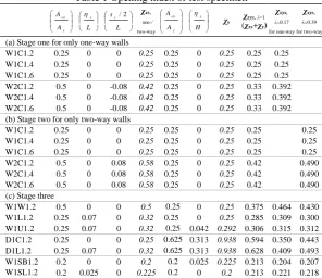
Table 1 Opening index of test specimen
x ox A A L x L sx/2
χxs, one-/ two-way y oy A A H y
χy χxys, λ=1 (χxs+χy)
χxys, λ=0.17 for one-way χxys, λ=0.39 for two-way
(a) Stage one for only one-way walls
W1C1.2 0.25 0 0 0.25 0.25 0 0.25 0.25 0.25
W1C1.4 0.25 0 0 0.25 0.25 0 0.25 0.25 0.25
W1C1.6 0.25 0 0 0.25 0.25 0 0.25 0.25 0.25
W2C1.2 0.5 0 -0.08 0.42 0.25 0 0.25 0.33 0.392
W2C1.4 0.5 0 -0.08 0.42 0.25 0 0.25 0.33 0.392
W2C1.6 0.5 0 -0.08 0.42 0.25 0 0.25 0.33 0.392
(b) Stage two for only two-way walls
W1C1.2 0.25 0 0 0.25 0.25 0 0.25 0.25 0.25
W1C1.4 0.25 0 0 0.25 0.25 0 0.25 0.25 0.25
W1C1.6 0.25 0 0 0.25 0.25 0 0.25 0.25 0.25
W2C1.2 0.5 0 0.08 0.58 0.25 0 0.25 0.42 0.490
W2C1.4 0.5 0 0.08 0.58 0.25 0 0.25 0.42 0.490
W2C1.6 0.5 0 0.08 0.58 0.25 0 0.25 0.42 0.490
(c) Stage three
W1W1.2 0.5 0 0 0.5 0.25 0 0.25 0.375 0.464 0.430
W1L1.2 0.25 0.07 0 0.32 0.25 0 0.25 0.285 0.309 0.300
W1U1.2 0.25 0.07 0 0.32 0.25 0.042 0.292 0.306 0.315 0.312
D1C1.2 0.25 0 0 0.25 0.625 0.313 0.938 0.594 0.350 0.443
D1L1.2 0.25 0.07 0 0.32 0.625 0.313 0.938 0.628 0.409 0.493
W1SB1.2 0.2 0 0 0.2 0.2 0.025 0.225 0.213 0.204 0.207
W1SL1.2 0.2 0.025 0 0.225 0.2 0 0.2 0.213 0.221 0.218
IV.
DRIVE
EQUATION
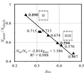
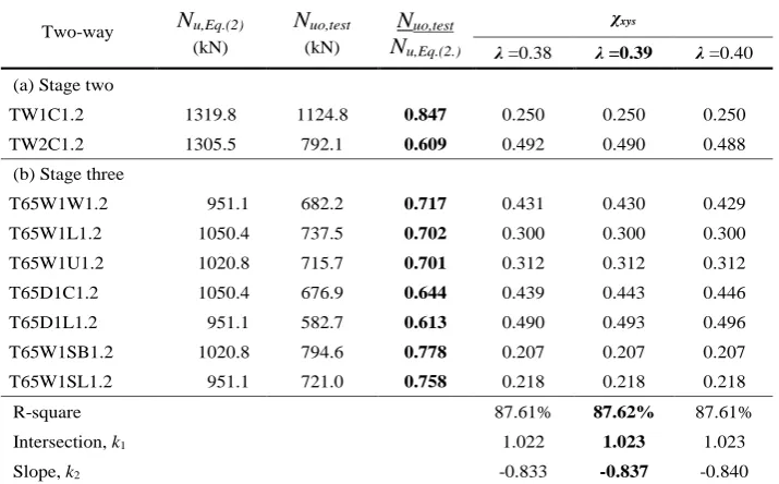
The reduced strength ratios between experimental ultimate load and predicted load by Eq.(2) for corresponding wall without opening was indicated with the opening index in Table 1 to derive a best fitting line as expressed intersection (k1) and indirect slope (k2) shown in Fig. 2 for one-way walls and Fig. 3 for two-way
walls. The weight ratios (λ) was controlled using iteration method to converge the maximum R2 value.
Eq.(3) can be rewritten according to the test properties shown in Table 2 including H/tw>27 for RC thin
17 . 1 17 . 0 014 . 2 386 . 1 5 . 109 1 6 . 1 24 . 0 7 . 0 ' , y xs w g c way one uo t H A f N (3a)
Figure 2 Derivation of k1, k2, and λ of walls in one-way action
Eq.(3) also can be rewritten according to the test properties shown in Table 3 including H/tw>27 for RC
thin walls with openings in two-way action,
Table 3 Regression analysis to determine λ of two-way walls
Two-way Nu,Eq.(2) (kN)
Nuo,test
(kN)
Nuo,test
Nu,Eq.(2.)
χxys
λ =0.38 λ =0.39 λ =0.40
(a) Stage two
TW1C1.2 1319.8 1124.8 0.847 0.250 0.250 0.250
TW2C1.2 1305.5 792.1 0.609 0.492 0.490 0.488
(b) Stage three
T65W1W1.2 951.1 682.2 0.717 0.431 0.430 0.429
T65W1L1.2 1050.4 737.5 0.702 0.300 0.300 0.300
T65W1U1.2 1020.8 715.7 0.701 0.312 0.312 0.312
T65D1C1.2 1050.4 676.9 0.644 0.439 0.443 0.446
T65D1L1.2 951.1 582.7 0.613 0.490 0.493 0.496
T65W1SB1.2 1020.8 794.6 0.778 0.207 0.207 0.207
T65W1SL1.2 951.1 721.0 0.758 0.218 0.218 0.218
R-square 87.61% 87.62% 87.61%
Intersection, k1 1.022 1.023 1.023
Slope, k2 -0.833 -0.837 -0.840
Figure 3 Derivation of k1, k2, and λ of walls in two-way action
The ultimate loads(Nuo) of RC thin walls with various openings subjected axial load in plane with an
International organization of Scientific
Research
91 | P a g e
Figure 4 Comparison between test result and corresponding prediction by Eq.(3)V.
CONCLUSION
To upgrade simplify national code equations, an experimental procedure including various opening configurations is carried out. Incorporating the experimental test, the ultimate axial strength equation of walls with openings is developed. The linear reduction strength due to openings is expressed by intersection(k1) and
proportional slope(k2) as 1.386 and -2.014 for one-way walls and 1.023 and -0.837 for two-way walls
respectively. The weight ratios (λ) also derived from the experimental results tested are 0.17 for one-way walls and 0.39 for two-way walls.
Exist the national codes had limitations; concrete strength under 65 MPa, height to thickness ratio under 30, walls restraint condition is simply supported on top and bottom edge only and omittable opening sectional area within 20%. The limitations are extended by the proposed empirical equation such that concrete strength up to 100 MPa, height to thickness ratio up to 40, restraint condition included simply supported on all side edge, and opening sectional area up to 50%. Particularly, opening index considering opening size and location in x- and y- both direction combined weight ratio λ. The equation and opening index are derived by testing results and regression analysis.
ACKNOWLEDGEMENTS
This study was supported by the Research Program funded by the Seoul National University of Science and Technology.
REFERENCES
[1]. J.H. Doh, and S. Fragomeni, Evaluation of experimental work on concrete walls in one and two-way action, Australian Journal of Structural Engineering, 6(1), 2005, 37-51.
[2]. S.M. Saheb and P. Desayi, Ultimate strength of RC wall panels in one-way in-plane action, ASCE Journal
of Structural Engineering, 115(10), 1989, 2617-2630.
[3]. J.H. Doh, and S. Fragomeni, Ultimate load formula for reinforced concrete wall panels with openings,
Advances in Structural Engineering, 9(1), 103-115.
[4]. S.M. Saheb and P. Desayi, Ultimate strength of RC wall panels with openings, ASCE Journal of
Structural Engineering, 116(6), 1990, 1565-1578.